
Audioholics Amplifier Measurement Standard
Measuring amplifiers - the Audioholics way
An Overview to Audioholics Power Amplifier Measurements
There has been much discussion on the major audio forums lately regarding A/V receivers and multi channel amplifier power output capabilities as well as their abilities to drive low impedance loads. Much of the controversy steams around the infamous " All Channels Driven Test " which simulates a best case test load in a worst case environment and by all intents and purposes an unrealistic real world scenario. For more information on this, the reader is encouraged to read the following articles:
All Channels Driven Test - Does your Amp Deliver?
The All Channels Driven Test Controversy
Product Managing Receiver Platforms
With that, lets all first remember that receivers in the $1k price range from the leading companies today are an absolute bargain regarding their processing power, features, and performance. I like to think of them as an excellent Preamp/Processor (usually rivaling many costlier Pre/Pros) with a free amp thrown in. Whether the amp section within the said receiver is " good enough " depends on the following variables:
- Loudspeaker Impedance
- Loudspeaker Efficiency
- Room Size
- Room Acoustics
- Listening Preferences
- Whether or not you apply bass management to your Loudspeakers and utilize a dedicated powered subwoofer(s).
As you can see, there are a number of variables and the answer is simply not that straight forward.
When conducting amplifier measurements, we tend to be a bit more forgiving with receivers than multi channel power amplifiers for obvious reasons. Most aren't designed to deliver rated power with all channels driven and most don't make any claims that they are.
As a result of all this dialogue, we have come up with a fair and equitable way of measuring power amplifier performance that not only tests rated power, but other aspects which directly affects how it will sound when powering various loudspeaker loads. Before discussing our methodology in how receivers or amplifiers should be measured, I felt it relevant to first give a history of my background since I am the primary reviewer that measures amplifier performance for the Audioholics publication.
My Background as an Electrical Design Engineer
After graduating college with my B.S.E.E. degree in Electrical Engineering, I went and worked for a telecommunications company where I designed analog front end and analog filters for DSL and phone applications. I also worked for a government defense contractor where I designed audio communication systems for NAOC, Air Force One and the White House. I sleep well at night knowing if our President orders a nuclear strike from NAOC, all of the generals will clearly hear and understand his orders because of my design efforts on the audio products used in that battle airplane.
My analog background over the 7+ years of doing design work really sharpened my skills, which gave me good intuition and perspective of how to properly measure and analyze amplifier performance. While doing design work, I always followed a very methodical four step scientific process for design that I learned as a degreed Electrical Engineer in college and a Senior Design Engineer in my profession.
Editorial Note on the Scientific Process Used for Product Development
Step 1: Hand Calculations & Circuit Analysis
I first started with a design concept on paper doing calculations based on proven circuit theory.Step 2: Build & Simulate Circuit Models
I then simulated the circuits using a program called PSPICE. I often had to build my own simulation models for parts that weren't in the parts library.Step 3: Build and Measure Actual Lab prototype
Step 4: Correlate data from Steps #1-3
I then built up test circuits in the lab to measure circuit performance.
Once I had a positive correlation between my hand design, PSPICE simulation and Lab performance, I then went on to spin a PWB to produce a full fledged prototype. The measurements I made in the lab had a direct correlation with real world performance. My bosses expected me to show such correlations before proceeding to final design.
Audioholics Amplifier Measurements Overview Interview
Why Does Audioholics Measure Amplifier Performance?
Personally we believe measuring amplifier performance for reviews has two purposes:
- ensures the manufacturer claims are true so that the consumer is getting what he/she paid for
- attempts to correlate subjective performance with measured performance
Audioholics Amplifier Measurements Evolution
 When we first started Audioholics, we only had an analog oscilloscope and resistor bank to do measurements on. It was a rather tedious and crude process but we pressed on until we could afford more advanced equipment. Then we became fortunate to acquire an Audio Precision SYS2722 and that opened up a world of new capabilities for us as it was the industry's most sophisticated but difficult to use Audio Analyzers.
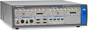
Recently we've replaced the venerable SYS2722 with the AP APx585 HDMI Analyzer which tests up to 8 channels, and is much easier to use. Ever since using the APx585 we've been able to apply a consistent measurement test suite to each amp and receiver we've measured on it which is outlined below. The APx585 doesn't come cheap. In fact the version we have represents a $40k investment. We don't know of any other A/V publication that is this committed to having the very best hardware to do amplifier measurements and only one amplifier manufacturer to our knowledge (Emotiva) that has made such a significant investment in analog test equipment.
The Measurements
Let's continue on and establish all of the relevant test criteria for gauging amplifier performance. Quantifying the measured results of the data below will directly determine just how well the amplifier performs and if it meets manufacturers specifications.
Frequency Response - measures the linearity of an amplifier or how well an amplifier will reproduce a signal without attenuation or boosting with ideal being flat within the range of human hearing 20Hz to 20kHz +/- 0dB. We test Frequency Response at all power levels and 8 and 4 ohm loads to ensure the amp doesn’t lose bandwidth under loading. We have seen poorly designed receiver amplifiers that simply lose power bandwidth when driving 4 ohm loads at full power. In such cases, we caution users to stick with 8 ohm rated speakers.
Since we never know what speaker a consumer is using, we test with dummy 8 and 4 ohm loads and comment on how its possible this response can affect sound quality depending on the load connected. The design goal for any good amplifier should exhibit ruler flat frequency response from 20Hz to 20kHz with less than .5dB of variation in that entire audio passband. We also check for channel to channel variation which to ensure each channel will play at similar volume levels given identical input source material. This is an important metric often overlooked by most review publications.
An amp that exhibits frequency peaking at high frequency can sound bright depending on the speaker load it's driving. There are exceptions to this rule in cases where Class D amplifier output filters can cause varying response slightly above the output filter which may or may not be sonically distinguishable depending on the speaker being powered.
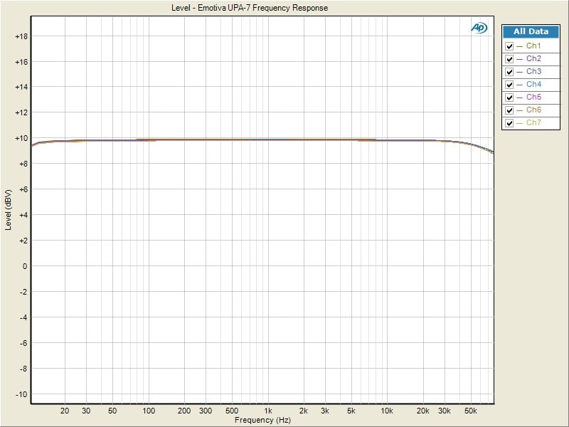
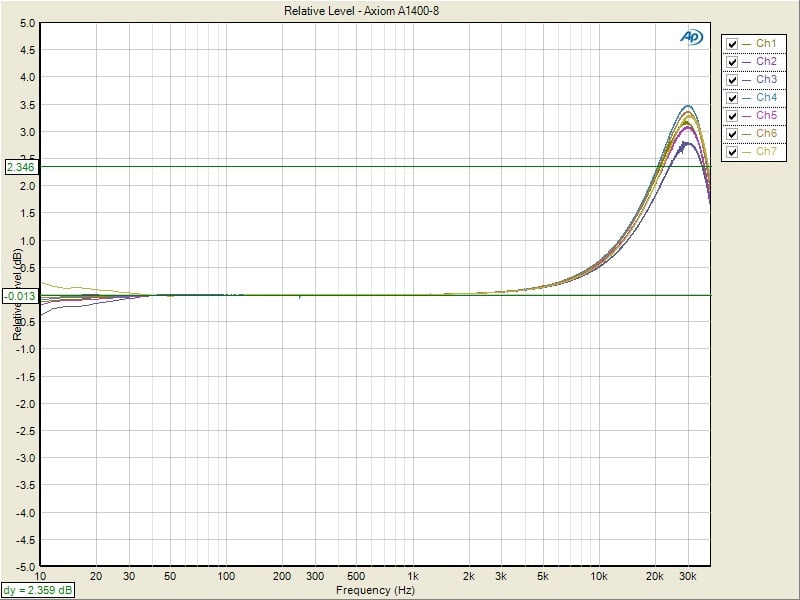
Emotiva UPA-7 (left pic) ; Axiom Audio A1400-8 (right pic)
Amplifier Gain - this is a measure of how much output voltage you will get given a fixed input voltage where Av = Vout/Vin. Amplifier gain (Av) is also measured to ensure it will be compatible with any potential mating preamplifiers. We like to see power amplifiers hit full rated power at 2Vrms or less as many A/V receivers preouts have limited output drive. If the power amp requires more than 2Vrms to hit rated power and the preamp can't deliver it, then the result will be a clipped preamp signal amplified by the power amplifier which will cause audible distortion and/or compression.
If an amplifier has unbalanced and balanced inputs, we like to see that they follow the THX Guidelines which is adopted from the pro audio world where:
Unbalanced: Av = 29dB (THX standard)
Balanced: AV = 23dB (6 dB lower than unbalanced)
The reverse should be true for preamps so that the output level when switching between balanced and unbalanced connections between the preamp and power amp remains constant.
THD and IMD Distortion - This is a measure of how well an amplifier can faithfully reproduce a signal without introducing any artifacts or harmonics. While this is an important metric to consider, most solid state amps these days boast pretty low figures here (usually well below audibility) and are rarely a real world problem for well designed amplifiers. In addition, distortion measurements into a resistive load are generally good on amplifiers. Reactive load distortion testing is rarely done, but of interest if a quality load could be constructed and not act as the distortion mechanism. This will be revisited at a later date and incorporated into this test procedure when appropriate.
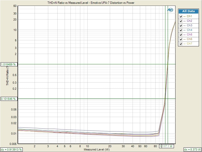
Emotiva UPA-7 1kHz Power Sweep vs Distortion (1kHz PSweep)
We do look at distortion at 1 watt and full rated power. We consider the fidelity firewall to be 0.1% rather than the industry norm of 1% typically found in other A/V publications. We are more interested in testing amplifiers under clean fullrated power than at power levels which can be seen as clipped signals on a crude Oscilloscope. Although our tabulated results are typically published at 0.1% numbers, you can still look at the graphs to figure out what the 1% power levels actually are if you want to directly compare power measurements to the print magazine ratings.
We take it one step further and look at FFT Distortion of an amplifier at 1 watt and full rated power.
THD Distortion Ratio vs Frequency - It's good housekeeping to sweep distortion vs frequency to see how the amplifier performs for the entire audio bandwidth instead of the typical discrete 1kHz single test tone. You may see us include these types of measurements in amplifier reviews or at least make reference to the fact that we did a distortion sweep vs frequency to look for any slew rated distortion problems.
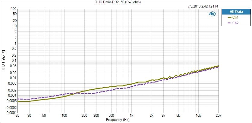
Outlaw RR2150 Distortion Ratio vs Frequency Sweep
FFT Distortion Spectrum - we test to see how clean the output is on an amp based on harmonics generated form a fundamental tone. Some people prefer the distortion profile of a tube amp which has more even order harmonic distortion. It's not our place to judge that but we do show how it measures. This also shows the noisefloor of an amplifier and if it has a problem with transformer hum (60Hz) or exhibits significant DC offset when driven at high power.

Marantz SR8012 FFT Distortion @ 1 watt
SMPTE Intermodulation Distortion
We just started including SMPTE IMD multi-tone distortion tests to see how amplifiers react to non harmonically related signals. This is important since these artifacts can make music sound harsh or fatiguing. The test signal consists of a 60Hz and 7kHz test signal summed together at a 4:1 amplitude ratio. 60Hz is an important frequency to show how well the power supply can reject residual noise coming from the AC line. 7kHz represents about the midband point of the human audio range and it's also a region where a lot of harmonic content is present in music.

Outlaw RR2150 SMPTE IMD Distortion Test
In this test, harmonics at 7kHz were -80dB or lower than the fundamental.
Power Measurements
Using our Audio Precision APx585 8-channel HDMI analyzer, we conducted a full barrage of multi-channel amplifier tests. We tested power using three methods all of which were taken at < 0.1% THD + N:
- Continuous Full Power Bandwidth (CFP-BW) from 20Hz to 20Khz into 8 and 4-ohm loads (up to two-channels)
- 1kHz Power Sweep vs Distortion (1kHz PSweep) - popularized by the print magazines, this is an instantaneous power vs distortion test at 1kHz. This is the test most manufacturers (and many print publications) do when rating their amplifiers " Continuous All Channels Driven". The problem with this test is it often masks slew related and or frequency response problems some amplifiers exhibit at the frequency extremes, and thus inflates the measured power results. It does provide an instant gratification number for consumers to argue over on the forums so we are now incorporating this test to please the masses. It also gives the consumers an apples to apples comparison between our ACD measurements and the measurements that the major print magazines do.
- Dynamic Power - (Dynamic PWR) - this is a dynamic power measurement using a 1kHz CEA-2006 Burst Method testing adopted from the car industry similar to IHF method only a bit more difficult for an amplifier and more representative of real musical content. This measurement will give you an idea how much dynamic headroom is available in the amplifier as it tests the robustness of the amplifiers power supply and output devices.
Keep in mind most review publications don't do continuous power measurements and they usually publish power measurements into clipping at 1% THD + N. Our measurements are very conservative as we use a dedicated 20A line with no Variac to regulate line voltage. We constantly monitor the line to ensure it never drops more than 2Vrms from nominal which in our case was 120Vrms.
For more info on amplifier measurements, see: The All Channels Driven (ACD) Test
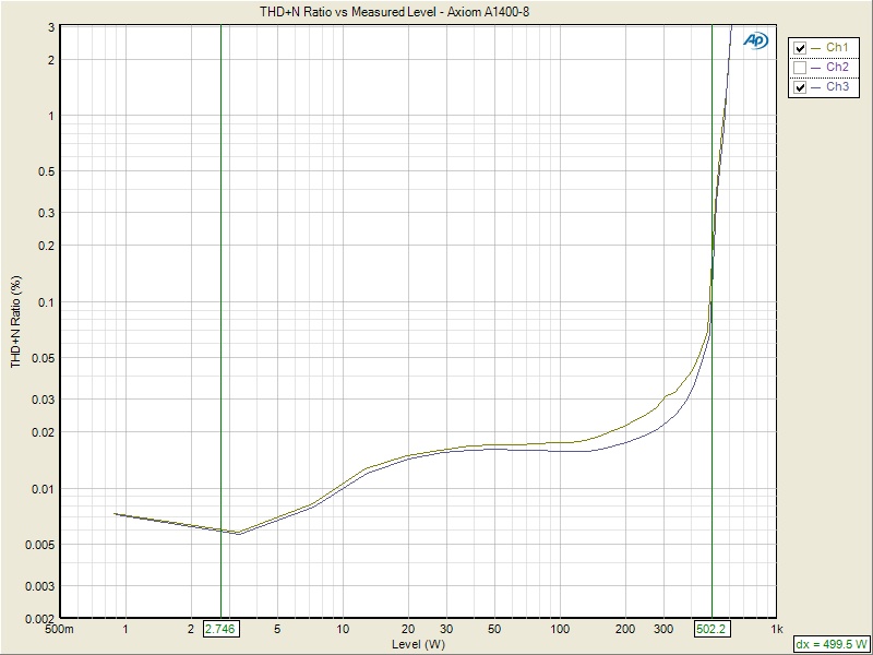
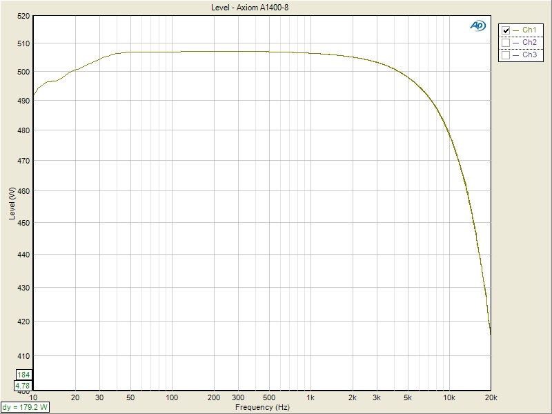
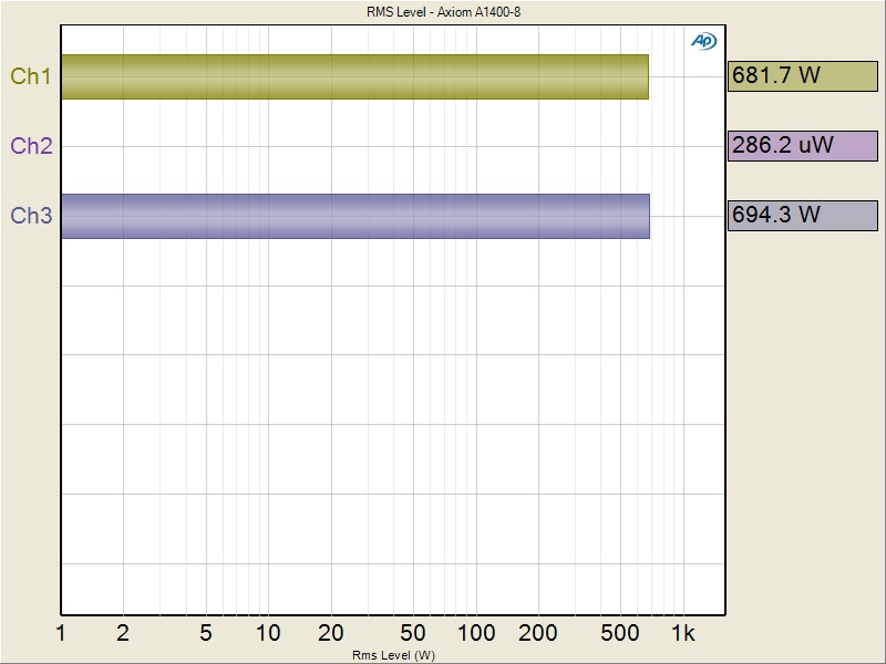
Axiom A1400-8 Power Tests: 1kHz Psweep (left pic) CPF-BW (middle pic); Dynamic PWR (right pic)
Once we've measured amplifier output power using the three methods above, we tabulate the results as shown below for easier readability.
| # of CH | Test Type | Power | Load | THD + N |
| 2 | CFP-BW | 140 watts | 8-ohms | 0.1% |
| 2 | CFP-BW | 238 watts | 4-ohms | 0.1% |
| 7 | 1kHz Psweep | 108 watts | 8-ohms | 0.1% |
| 7 | 1kHz Psweep | 117 watts | 8-ohms | 1% |
| 2 | 1kHz Psweep | 240 watts | 4-ohms | 0.1% |
| 2 | 1kHz Psweep | 252 watts | 4-ohms | 1% |
| 7 | Dynamic PWR | 156 watts | 8-ohms | 1% |
| 2 | Dynamic PWR | 320 watts | 4-ohms | 1% |
Emotiva UPA-7 Power Measurement Table
Signal to Noise Ratio - This is a measurement of importance to consider as it is a ratio of the magnitude of the signal and background noise. Many amplifier manufacturers publish their SNR figures at full power, which can be misleading and hard to compare between different amplifiers at differently rated power levels. Many also apply weighting filters to yield better results such as A-wt or C-wt. This can make over a 10dB difference compared to unweighted measurements and should be noted when comparing various amplifiers. It is best to look at 1 watt levels (where the amp spends most of its time) and interpolate the SNR at the amplifier's full rated power. Unless we are measuring Class D amplifiers, we apply no weighting in our SNR measurements. Class D's do require weighting filters to reduce out of band noise and also prevent slew induced distortion on test equipment from corrupting the measurement. We like to see an amplifier be able to deliver at least 80dB @ 1 watt to ensure it has a low enough noise floor to not mask subtle details of music when listening at low power levels.
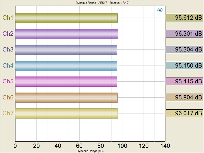
Emotiva UPA-7 SNR @ 1 Watt
Crosstalk - measures channel to channel isolation. We take it one step further and do All-to-One crosstalk measurements where all channels but the channel under test act as a noise source. This measures stereo separation. We test this at 1 watt and full rated power to ensure issues such as magnetic coupling or power transformer saturation don't adversely affect performance. We like to see a number of at least 60dB @ 10kHz for channel to channel crosstalk and about 50db when its a seven channel amp doing All-to-One crosstalk measurements.
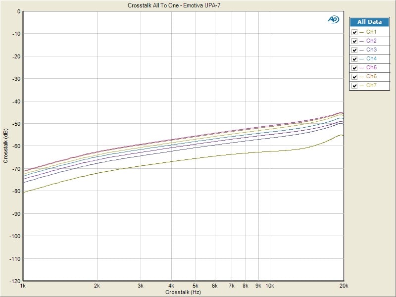
Emotiva UPA-7 All-to-One Crosstalk @ full Rated Power
Amplifier Output Impedance - This again is an important metric as it determines the amount of interaction or frequency response variation an amplifier may produce when driven by a reactive loudspeaker load. Usually lower is better, but some do prefer high output impedance tube amps for example since they can excessively roll off high frequency response and result in a warm sound. We like to see amplifier output impedance at 100mohms or lower for the entire audio bandwidth. Class D amps tend to have higher output impedance because of the output filter. The Axiom A1400-8 as shown below is an exception to what we've seen with most Class D amps.
Note: sonically preferring something doesn't necessarily mean its more accurate or precise.
We used to show these measurements in older reviews, but since we now incorporate so many other tests, we try to keep the objective analysis more concise and readable. We only now publish output impedance if we find it to be excessively high. A very high output impedance such as those found in tube amps or Class D amps with minimal post filter feedback can drastically affect how the amp sounds depending on the loudspeaker load it drives. A low output impedance ensures an amp will sound more consistent regardless of the load attached to it.
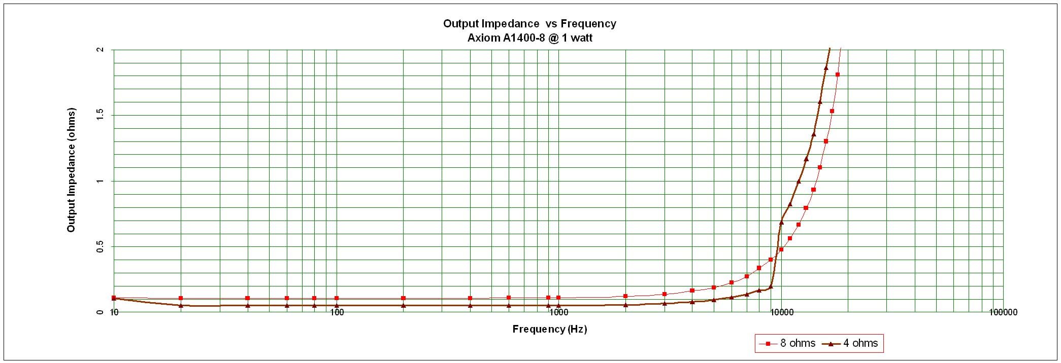
Axiom A1400-8 Output Impedance
Damping Factor - This specification is somewhat overstated by most manufacturers and the reader is encouraged to reference our article: Damping Factor - Effects on System Response for more information.In real world scenarios, cable impedance usually nullifies the benefits of a very high damping factor and thus beyond a certain value as stipulated in the aforementioned article it becomes mostly academic.
I still like to check for this if we also measure output impedance, as it is a good indication of amplifier output impedance and power supply capability. we like to see a minimum damping factor of 50. If the output impedance maintains our 100mohm preference, then damping factor should also meet our 50 mark with no issues given their direct relationship.
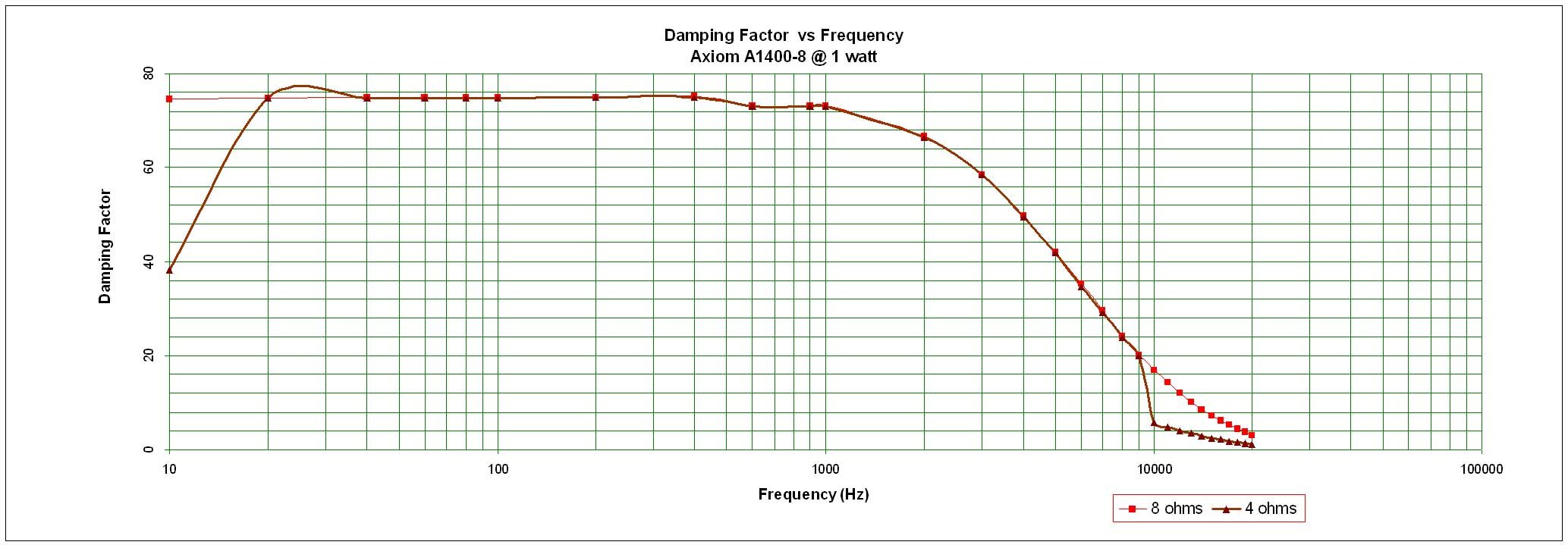
Axiom A1400-8 Damping Factor
Conclusion
That's about all there is to measure with respect to amplifier performance. How we hear/perceive sound is a different story since we all have our individual preferences. Sound is as much of an emotional process as it is an audible one.
That being said, it's important to note we do all of my listening tests of amplifiers BEFORE conducting any measurements. This ensures we are NOT pre-biased by a measured outcome. We have measured amps in the past that didn't do so well on the test bench but sounded fine in the real world. In such instances that is clearly noted in the review. Our ears are far more forgiving than our test equipment in most cases.
Its because of our rigorous testing methodology that many of the big manufacturers in this industry contract me to do Beta testing of their amplifiers and receivers before they go to market. I've also worked very closely with the fine folks at Audio Precision to devise better testing methods and I am still working on refining them even further. We hope to do reactive load testing in the future using a load that everyone can agree upon being a typical loudspeaker load for consumer audio. I am always evolving our testing procedure and methodology whenever possible.
I also recommend you watch the Audio Precision Seminar about measuring amplifiers they gave at our last annual SOTU event held at Disneyworld.
Editorial Note: How to Measure Amplifier Output Impedance & Damping Factor Using an O'Scope & Test Load
Back in the day, I used to use an Oscilloscope to measure amplifier output impedance and damping factor. Now I do a similar method as indicated below but generate the frequency sweep on my Audio Precision APx585. I then import the data into Excel, perform math functions and graph the results. For those wanting to experiment, I outline a procedure below.
Required Test Equipment
Non inductive Resistors (8 ohms, 4 ohms)
Oscilloscope
Short 10AWG Speaker Cables
Function Generator
Measuring Output Impedance and Power of Amplifiers

Step 1: Adjust the function generator until you read 2.82Vrms on the unloaded amplifier as depicted in the left figure above. Record these results in Table 1. under "Vopen" over the entire frequency range.
Step 2: Attach a non inductive Load to the amplifier and re-measure the output voltage over frequency and record the data in the appropriate "Vload" column specific to the load impedance used in this test in the three Tables below. Do NOT vary amplitude of the function generator, only Frequency.
Step 3: Calculate the amplifier output impedance (Zo) and Damping Factor with the following relationship:
VLoad = (RL / RL+Zo)*Vopen
Solve for Zo = > Zo = RL*Vopen/VLoad - RL
Damping Factor = Zload / Zo
Step 4: Plot the data from the Tables into Figures in Excel.
Step 5: Find the maximum unclipped voltage the amplifier can provide into the specified test load
Step 6: Record the voltage over the specified frequency range.
Step 7: Detach the test load and record the voltage "Vopen" vs frequency repeating step 3 to calculate output impedance.
Note: The following variables limit the absolute accuracy of this test method:
Cable impedance and stray inductance in resistor
Variance in line voltage (since all tests are done without a line stabilizer)
However, this is more of a real world than typical ideal test condition, thus for all intents and purposes serves well for this application.
Test Notes

-
Record the 8ohm test load + test cable measurements: (ie. Rdc = 8.04 ohms ; Ls = 5μH (1kHz) )
-
Record the 4 ohm test load + test cable measurements: (ie. Rdc = 4.03 ohms ; Ls = 3.8μH (1kHz) )
-
All measurements should be done in "Pure Direct Mode" or analog bypass
-
If Line Voltage is NOT held constant, variance (if any) should be noted in the measurements
-
All tests should be conducted using EXT Multi-CH Inputs and Outputs when appropriate
Gene manages this organization, establishes relations with manufacturers and keeps Audioholics a well oiled machine. His goal is to educate about home theater and develop more standards in the industry to eliminate consumer confusion clouded by industry snake oil.
View full profile