
Dielectric Absorption in Cables Debunked
Dielectric in Capacitor
Before we debate the relevancy of Dielectric Absorption relating to speaker cables, and commonly perpetuated by many exotic cable vendors and cable cult hobbyists, let us first define the roll of a dielectric.
According to Wikipedia ( http://en.wikipedia.org/wiki/Dielectric ) the definition a Dielectric material is an insulator. The ideal dielectric would be a vacuum or infinite impedance. However, real world dielectrics do NOT have infinite impedance and therefore are not perfect. As frequency increases, the Dielectric starts exhibiting shunt resistive losses which can be measured and quantified as signal loss across the termination load. Fortunately for our application (audio) these shunt losses don't begin to surface until frequencies much higher than the audio bandwidth.
At audio frequencies, even the worst dielectrics (ie. Polyvinyl Chloride, aka. PVC / plastic) used in cheap and many exotic speaker cables maintain shunt resistive impedances in the mega ohms or more. When dealing with a low termination impedance of a loudspeakers (usually in the order of several ohms) the dielectric shunt resistance is on the order of 10^6 greater, thus the parallel impedance remains virtually unaffected and we see no losses due to the dielectric at audio frequencies.


This is a basic model for a speaker cable where Rs represents the AC and DC resistive losses, Ls represents total loop inductance, Cp represents pair to pair cable capacitance and G represents conductance ( 1 / Rdielectric). All dielectrics have what is known as "loss tangents" or dissipation factors. The reason it is called "loss tangent" is because it is the tangent of the angle between G(which is real) and admittance Ycapacitance = 2*pi*f*C (Which is imaginary). Since both G and Ycapacitance are both functions of frequency, the tangent (or ratio of the two) is frequency independent. If there where no dielectric loss, Rshunt would equal infinity and G would be zero, therefore the tangent of the angle between them would also be zero.
In this case, we will consider standard 12AWG Zip Cord with PVC insulation where measured Cp = 14pF/ft.
G can be found by the following relationship:

where d = loss tangent ; Cp = cable capacitance
|
Frequency |
er |
d |
G |
Rdielectric |
|
60 Hz |
3.20 |
0.0115 |
6.07*10^-11 |
16.47 * 10^9 ohms |
|
1 kHz |
3.1 |
0.0185 |
1.63*10^-9 |
6.13*10^8 ohms |
|
1 MHz |
2.88 |
0.0160 |
1.4*10^-6 |
7.1*10^5 ohms |
Reference: Data for Engineers by Howard Sams
As you can see, Rdielectric is infinitely large even up to 1MHz compared to the load impedance of a loudspeaker. G is typically on the order of 10^-6 for most materials used for cables and its losses become significant at much higher frequencies than audio (usually in RF regions after heavy skinning has already occurred).
The reason that we usually use conductance (or admittance) for the shunt element, instead of impedance, is that conductances in parallel add directly. Thus another way of showing the dielectric losses (or lack thereof):
For resistors in parallel we know that Rtotal = (R1 * R2) / (R1 + R2). Since G = 1 / R we can rewrite this equation as;

Multiplying the numerator and denominator by G1*G2 gives;

Gtotal = Gdielectric + Gspeaker where Gspeaker = 1 / Rspeaker. Substituting numbers for a 4 ohm speaker impedance

Thus the dielectric losses at audio frequencies where the cable is terminated into a low impedance load such as a loudpeaker are insignificant.
Signal Integrity Experts such as Dr. Howard Johnson have firmly established that there are four frequency regions when dealing with signal propagation.
- RC region
- LC region
- Skin-effect region
- Dielectric loss region
- Waveguide dispersion region
Within each region the requirements for termination and critical metrics differ, as do the tradeoffs between length and speed. Remarkably, this relationship holds true for any type of metallic transmission media across all four regions.
The transmission line losses contain conductor and dielectric losses. The conductor losses may be in turn be represented as DC resistive losses plus skin effect losses, with the latter becoming more significant as frequency increases. At sufficiently high frequencies (exceeding 1 GHz) the impact of dielectric losses being proportional to frequency tend to dominate over the Ohmic resistance (frequency independent) and also the skin effect (which varies with square root of frequency). The losses for speaker cables at audio frequencies are predominantly in the RC region with secondary considerations in the LC region above 10kHz. Skin effect losses are negligible in this case as illustrated in our many cable articles:
To better understand the relationships between frequency and impedance of transmission lines, I suggest the following paper authored by Belden Cable and hosted by DuPont.
Characteristic Impedance of Cables at High and Low Frequencies
Transmission Line Effects
If we use classic and proven transmission line theory to determine the importance of cable impedance matching at audio frequencies, we derive the following:
wavelength (in meters) = v / (f*sqrt( e r))
Where f is the frequency of the signal in Hz, v is the velocity of the signal =
3x10^8 meters/second (vacuum) and er = dielectric constant
The limit of human hearing is about 20kHz. However if we consider the audio bandwidth limitation to be 100kHz (based on maximum bandwidth of high resolution audio formats such as DVD-A and SACD, and considering sharp rolloff of power amplifiers to preserve SNR and stability), using a solid dielectric, with approximately the same dielectric constant for our cable as PVC where:

where er = 3.1 for PVC, we calculate a Velocity of Propagation (Vp) of about 56%.
This cuts the physical wavelengths where impedance matching matters to 1,680 meters or 5,511ft. A quarter wavelength, which is often used as the benchmark for where the characteristic impedance of a transmission line becomes critical, is then 420 meters or 1,377 feet. Many think a quarter wave is a bit too long to use, and prefer to go with 1/10 wavelength or so. If we are considering ultra high performance, and use the 1/10th wavelength more conservative estimate to determine the point at which the cable's electrical length becomes long (with respect to a wavelength) to consider transmission line effects for audio cables, we derive 168 meters or 511ft. If you consider using common low resistance 12AWG Zip cord (3.27 ohm/1000ft loop resistance) as speaker cable at this length, then you would effectively be placing 1.7 ohms of resistance in series with your amplifier and speaker.
With a nominal 4ohm impedance speaker, the resistive losses at these cable lengths would dominate and result in over 2.4dB of signal loss alone, not to mention destroying the damping factor of the system. Add in the reactance losses (inductance and capacitance) and we see a whopping 11dB of loss (not factoring in any potential amplifier stability issues from the high reactance of the cable).
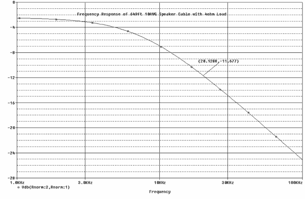
My point here is the lumped impedance losses alone would have a far more profound affect than transmission line and/or distributed losses could ever dream of having.
Let's put aside the obvious about the unimportance of transmission line effects on speaker cables for a moment and look at the dielectric to determine if dielectric absorption can cause signal loss or distortions at audio frequencies like many exotic cable vendors claim.
When used as the insulating dielectric of a transmission line, dielectric losses translate into measurable signal attenuation. The higher the dielectric loss, the MORE attenuation. Dielectric loss is a function of frequency. In long cables, the dielectric properties are more significant. Typical PVC insulation has a measurable dielectric loss at 10MHz which is almost 3 decades past the limits of human hearing (~20kHz)! Since Dielectric losses increase with frequency, they are often lumped with skin effect losses into an overall dB loss model.
Dielectric Absorption in Cables Debunked - Measurements
If we examine an allegedly horrible cable regarded by many so called audiophiles (12AWG Zip Cord), we can see the effect of Skin effect (increased AC resistance, decreased internal inductance).
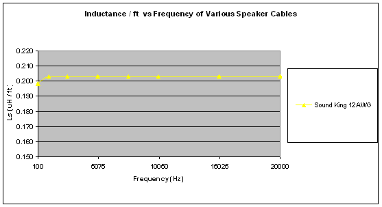
We learned how to calculate inductance of speaker cables in Calculating inductance of twin feeder (Zip Cord) . This concept can be used for all cable geometries, but the math becomes somewhat more complex using superposition for multi conductor insulated Litz style construction. However, this goes beyond the scope of this article and the point here is to show that at audio frequencies the inductance remains extremely uniform, thus the increase in skin resistance is NOT significant enough to minimize internal inductance.
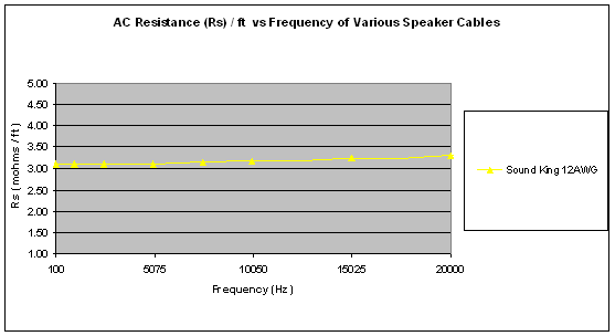
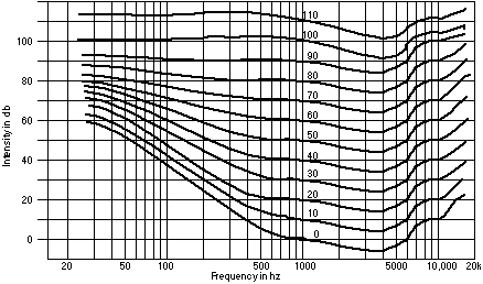
Here we see a slight elevation of AC resistance due to skin effect at 20khz. But when we look closer we see note the DC resistance of the cable is 3.27 mohms/ft and the Rac at 20kHz = 3.31 mohms/ft which represents a meager 1.2% increase in resistance due to skin effect. To put this in terms of signal power loss would be: 20*log (3.27/3.31) = .051dB! Studies in acoustics have proven the human ear is not capable of discerning level differences of less than about 0.5dB which is 10 times greater than the loss we see from Skin Effect! In addition, the human ear is extremely insensitive to amplitude changes at very low and high frequencies based on the Fletcher and Munson Curves . Check out our article for an in-depth look at Skin Effect and how the human ear works, check out our Physics tutorial .
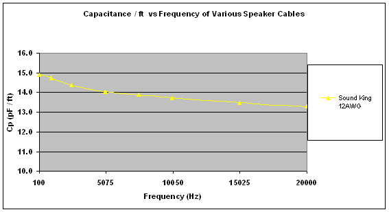
Here we do see the capacitance decreasing with frequency but not because of Dielectric absorption. What we are seeing here is a combination of slightly decreasing dielectric constant with frequency and slight fluctuation in measurement due to instrumentation error of cable inductance isolating the very small value of capacitance as frequency increases. The most accurate measurement of capacitance in this case is from about 1kHz to 10kHz. If we take an average value, then 14pF/ft seems reasonably accurate.
Dielectric Absorption in Cables - Calculating Metrics
This spreadsheet calculates Cp, Ls and Z0 for a parallel pair cable, for various effective dielectric constants. The real trick here is to know what to use for the effective dielectric constant, since part of the field is in air and part is in the cable dielectric. The percentage in air also varies with the conductor spacing. The greater the spacing, the larger the percentage of the field that is in air. Therefore, the effective dielectric constant decreases with increasing conductor spacing. What is often done is that the cable capacitance is measured and compared to the calculated values to determine the effective dielectric constant.
The following spreadsheet includes a more complicated exact equation for capacitance, instead of the simpler and more commonly quoted approximate equation (which requires 2r/d < < 1). Also in the inductance equation L included the internal inductance term.
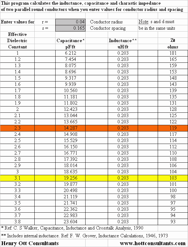

While the Dielectric Constant for PVC is generally known to be about 3.18. However, it turns out our effective dielectric in this instance is more like 2.3 (based on our measured Capacitance value of 14pF/ft). As you can see in the previous data table, the Dielectric Constant has NO effect on inductance, only capacitance which in turn affects the cable characteristic impedance (not relevant at audio frequencies since transmission line effects and impedance matching between a low output impedance amplifier and variable complex load impedance of the speaker are negligible).
So What Have We Learned?
This exercise has taught us yet another marketing claim surrounding many exotic speaker cables regarding the relevancy of Dielectric Absorption and/or the role the Dielectric plays on transmission line effects at audio frequencies is yet another snake oil myth. We have proven that the shunt losses due to the dielectric are negligible at audio frequencies. The major relevancy roles of the dielectric in this application are to serve as isolation between the two conductors and control the capacitance of the cable based on the conductor spacing and dielectric constant. If an exotic cable vendor, salesman, or cable cult hobbyist claims otherwise, tell them you know better and point them to this article.
Addendum: A Note About Dielectric Absorption or Loss Tangents
(added 4/27/2004)
There are some cable hobbyists and exotic cable vendors that often confuse or even abuse the term "Dielectric Absorption" and its role on a speaker cable compared to a non linear capacitor.
For a capacitor formed from a lossy dielectric material, the loss tangent is the ratio at any particular frequency between the real and imaginary parts of the impedance of the capacitor. A large loss tangent means you have a lot of dielectric absorption. This article demonstrated that this is not a factor with speaker cables given the frequencies and impedance characteristics for the application we are dealing with. Back to capacitors, if you construct a capacitor C from a lossy dielectric, the dielectric absorption causes the value of C to change with frequency. For a good dielectric, the value of C will very slowly deteriorate with frequency. For poor dielectrics with higher dielectric loss, the decay in capacitance with frequency will be more prominent. The rate of deterioration in capacitance is directly linked to the loss tangent. Speaker cables are partially encased in the dielectric and free space so their effective dielectric is much lower than the actual dielectric as I have shown in the cable calculator and measurements within the article. "Since both G and Ycapacitance are both functions of frequency, the tangent (or ratio of the two) is frequency independent. Thus the ratio of the two cancels the frequency dependence between them.
As shown by this equation  , the shunt losses of the dielectric can be derived from the loss tangent or dielectric absorption factor. For more info on this, I suggest reading this excellent High Speed Board Design Tutorial written by Altera.
Updated 4/27/2004
Gene manages this organization, establishes relations with manufacturers and keeps Audioholics a well oiled machine. His goal is to educate about home theater and develop more standards in the industry to eliminate consumer confusion clouded by industry snake oil.
View full profile