
Loudspeaker Cabinet Bracing: A Detailed Look on Do's and Dont's
RBH Sound Status Acoustics Titus Subwoofer
A recent Audioholics article titled “Identifying Legitimately High Fidelity Loudspeakers: the Myths & Facts about Cabinets” posited that one measure of quality is in a well-braced cabinet. Poorly or improperly braced loudspeaker cabinets vibrate unduly, coloring the overall acoustic output and lowering fidelity. In this article, we will explore the reasons that a stiff cabinet is a desirable feature of a well-designed loudspeaker based on established engineering mechanics. We will also discuss how improper understanding of this subject matter and a limited amount of measurement of a test mockup could falsely lead one to believe that using fewer braces, thereby lowering the panel resonance of a cabinet, is desirable. As you will see in this analysis, the stiffer the cabinet, the lower the resonances become which will greatly reduce unwanted colorations of sound.
The approach taken here will be to look at the behavior of an individual panel of a loudspeaker cabinet. In the course of the analysis, certain idealizations and assumptions will be made to keep the analysis as simple as possible. Adding in the other panels, bracing, and holes for the drivers with additional mass present in the complete cabinet would introduce further complexity along with partial lateral and rotational restraint at the panel edges and brace ends along with the interaction that would develop with those other components. The exact numbers we get will not precisely describe any particular loudspeaker, but it will display behavioral trends that will occur in the complete system. The intent is to keep the focus on these trends without obscuring them by the additional complexity that would be introduced when accounting for the full system.
A purely analytical approach is decidedly different from what is done in the audio industry where prototyping and mockups are a common approach to design. Structural Engineering practice relies heavily on analytical tools to determine the behavior of structures for design. Buildings and other large structures are unlike mass produced products in that each is often unique, so it is not practical or feasible to create prototypes of every structure. Instead, analytical and design techniques are frequently developed and validated in laboratory testing of scaled physical models. The results of this work are then used by industry standards committees for codification to use in design practice.
Defining the Relation of Sound, Mechanical Vibration, and Cabinet Design
First, we will lay a little groundwork for our discussion. Let us start with a simple premise: sound is mechanical vibration, and the majority of readers here are well aware of this fact. Sound reproduction is an attempt to store those vibrations in some fixed medium for later playback that will mimic, as closely as possible, the original waveform of the sound, with the term fidelity used to describe how well that process is achieved. There are many factors that can reduce fidelity in sound reproduction, but few are as susceptible to problems as the final step, where the stored waveform is converted back into mechanical vibrations by a device called a transducer, commonly known as a loudspeaker
Idealized design of a loudspeaker system defines specific components, the drivers, which are intended to vibrate and radiate the reconstituted sound. All the other components in the system, including the cabinets that provide physical support to the drivers should be completely inert and not undergo any mechanical vibration at all. Such an idealization implicitly requires that these other components be infinitely stiff to prevent extraneous vibration. In the real world, this is not possible, so the task to properly engineer a loudspeaker system becomes an attempt to minimize any extraneous vibration and make it inaudible to the listener. To accomplish this, the cabinet has to be made stiff enough to drive the natural frequencies of vibration out of the audible range, or at least out of the range where the cabinet vibration will unfavorably interact with the drivers.
The cabinet is almost invariably the largest component of a loudspeaker system, which makes the design crucial for two reasons. First, the significant surface area of the cabinet can contribute larger amplitude displacements, making it more difficult to control the audibility. Second, stiffness and the natural frequencies of vibration are functions of the physical dimensions of an object, so that relatively large size works against efforts to keep vibrations out of audible ranges.
Now that we have defined the need for stiffness in a loudspeaker cabinet, we must go about determining how to achieve this in a practical loudspeaker design.
In this discussion, we will investigate some of the mechanical parameters that are involved in minimizing unwanted acoustic vibrations. From this, we will develop an analysis that will demonstrate the trends in the relationship between the magnitude of cabinet vibration and sound pressure.
First, we will describe some of the mechanical theory behind what is going on in closed form mathematical solutions. Then, because the closed form solutions are for idealized behavior that is used to simplify the mathematics, we will perform a finite element analysis using SAP2000, an analysis software package by Computers and Structures, Inc., to get a more complete look at the behavior of a speaker panel with different configurations of braces.
Loudspeaker Cabinet Bracing: A Little Theoretical Background
On a fundamental level, stiffness is an object’s resistance to distortional movement caused by a force. Stiffness is the mathematical inverse of compliance, which is more commonly used in audio, and as such, it is defined in units of force divided by length.
The physical parameters that go into determining stiffness are a complex function of many factors. Material properties, the physical dimensions of the object’s cross section, and the distance it spans while supporting the force all come into play along with how the load is applied and how the object is supported.
The reason we are concerned with the stiffness of a loudspeaker cabinet is the relation between sound and movement. Sound pressure level is a function of movement within the medium that is transmitting a sound wave, which in our case is the air. Particle displacement can be related to sound pressure with the following one-dimensional equation:

Where omega is the circular natural frequency, rho is the density of the transmission medium, c is the speed of sound in that medium, and x is the displacement. Circular natural frequency can be related to the natural frequency, in Hz:

This general relationship states that greater particle movement leads to greater sound pressure. Sound pressure is also related to particle velocity and acceleration, both of which are related as derivatives of position with respect to time.

Relating the fluid displacement to the displacement of the cabinet becomes a problem of fluid-structure interaction. For lightly damped structures, sound pressure peaks from mechanical vibration occur at frequencies very near the structural modes. The complex pressure field in three dimensional space can be related to the vibration of a rectangular plate of length a and width b in a spherical coordinate system:

Fluid-structure interaction is a complex problem to solve that involves linking mathematics between two traditionally separate braches of physics, solid mechanics and fluid mechanics. For our problem, the solution to the fluid-structure interaction problem is further complicated by two different volumes of air internal and external to the cabinet, three interaction surfaces, and both direct and indirect sources of vibration from the driver to the cabinet. A full study of a multi-physics phenomenon such as this is beyond the scope of the current discussion. What we are interested in is establishing the general trend for the magnitude of unwanted acoustic output as a direct relation to the amplitude of cabinet vibration. To that end, we will not consider certain aspects of fluid-structure interaction including the effect that internal cabinet pressure will have on the vibration of the cabinet.
We will now proceed by addressing the dynamic behavior of the cabinet. First, we need to define the mechanical behavior of the cabinet by establishing the equation of motion for the system:

Where m is mass, c is viscous damping, k is stiffness, F(t) is a forcing function that varies over time t, x is the displacement of the system, and the single and double dot over the x indicate the first and second derivatives of the displacement with respect to time, namely velocity and acceleration, respectively. The stiffness term is the mathematical inverse of compliance, or flexibility, which is more commonly used in the audio.
Rearranging terms and setting the force to zero, we can solve for the natural frequency of the system:

These other terms are the undamped circular frequency and the damping ratio respectively:

When damping is included, we can redefine the damped circular frequency as:

Of note, the Q factor that is often used in audio can be defined as:

Thus, the fundamental natural frequency, in Hz, of an object can be determined from knowledge of the stiffness and mass of an object as follows.

There are, of course, additional natural frequencies of vibration, harmonics, which can be defined over the geometric field of stiffness and mass for physical objects. Each frequency is associated with a unique deformed shape known as mode shape and within these mode shapes, are certain locations that effectively have no movement, which are known as inflection points. The solution for the frequencies and mode shapes of a physical object are known as modal analysis or eigenvalue/ eigenvector analysis.
Modal analysis is non-dimensional, meaning that it will determine the relative deformation within the panel at each resonant frequency, but not the actual magnitudes of the deformations. Effectively, modal analysis determines how an object wants to vibrate when subjected to an arbitrary impulse and then allowed to vibrate freely without the continuing application of force. To visualize modal behavior, think of a struck tuning fork or a plucked string on a musical instrument.
The behavior of the cabinet panels can be described using plate theory. For simplicity, we will look at an individual panel of a cabinet along with any braces used to reinforce that panel while under a uniform surface load from pressure.
For a rectangular plate with edge dimensions a and b, and thickness h, under uniform load q, we can determine the static load deflection w from the following fourth order partial differential equation in the xy plane:

The term D is the flexural rigidity of the plate with a thickness of h:

The variables E and v are the Modulus of Elasticity and Poison’s Ratio, respectively, for the material.
The differential equation for the plate can then be solved for different support boundary conditions. For our situation with a speaker cabinet panel that is supported on four edges, we can determine an upper and lower bound on the amount of deflection due to a load, and therefore the stiffness, by assuming a case where the edges are completely free to rotate and where the edges are completely restrained from rotating. In reality, panel edges are partially restrained by the stiffness of the other panels that make up the cabinet, so we know the real behavior is somewhere between these bounds.
Rotationally unrestrained edges: 
Rotationally restrained edges: 
The terms Em and Hm are the bending moments developed along the edge due to the rotational restraint with:

A uniformly loaded plate will produce either triangular or trapezoidal shaped reaction forces on supporting edges depending on the aspect ration of the sides. When the sides are not equal, the shorter edge will always see a 45o triangular reaction and the longer side will see a trapezoidal reaction unless all the sides are equal.
The behavior of the braces can be described using beam theory. The differential equation for a beam is also fourth order with length along the x axis:

The term EI is the flexural rigidity of the beam, comprised of the material modulus of elasticity, E, and the moment of inertia of the cross section, I, which for a rectangular beam of a cross section width b and depth d is:

We can then solve for the loading and boundary conditions as we did before with the plate.
For an unrestrained beam of length l under a triangular load
of q(x): 
For a restrained beam of length l under a triangular load of
q(x): 
Note that qo is the peak magnitude of the triangular load q(x) at the center of the beam.
Considering the original equation of motion under static load conditions, where the first and second derivatives of displacement, velocity and acceleration, are insignificant, it reduces to F = kx. Rearranging this equation to solve for the stiffness, we get k = F/x, the applied force over the resulting deflection.
Loudspeaker Cabinet Bracing: Qualitative Analysis
The preceding discussion provides a basis to proceed to look at how bracing will help in designing a speaker cabinet to minimize the amplitude of vibration when exposed to a time varying internal pressure.
There are two different ways to look at the behavior of a speaker panel and bracing system. There is the global behavior of the entire panel system, and there is the local behavior of the panel at the braces. The goal of increasing the stiffness of a speaker panel is two-fold, to decrease the overall deflection of the system under dynamic load and to increase the natural frequency away from the operating frequencies of the drivers. This task could be accomplished in one of two ways, either by increasing the overall panel thickness or by adding braces. Thickening the entire panel is a global approach to the problem, while adding discrete stiffeners is a local approach.
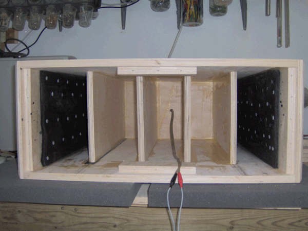
For discussion, we will look at the side panel of a cabinet that is 40 inches tall x 18 inches wide with and without braces. The braces used will be 2 inches deep and arranged at even intervals parallel to the 18 inch side of the panel with full coupling to the panel assumed. This is important in that if the connection itself is soft, it will reduce the effectiveness of the bracing. Both the panel and the braces will be made of ¾ inch thick MDF, as is common practice in the loudspeaker industry, with the following material parameters:
- Modulus of Elasticity: E = 580 kilo-pounds/sq inch (ksi)
- Unit Weight: g = 50 pounds/cu foot (psf)
- Poisson’s Ratio: v = 0.25
If, for simplicity, we will only consider the upper bound case for deflection with panel edges and brace ends that are laterally restrained, but not restrained against rotation, we can identify trends in the panel behavior as braces are added. Another simplification we will make concerns the changing boundary condition of the sub-plate edges along braces. We will idealize each sub-panel edge to be the same as the overall panel edges, by ignoring the deflection of the brace and the rotational restraint provide by adjacent sub-panels. This simplification will be eliminated in the subsequent finite element analysis.
From standard tables for plate deflection using v = 0.3, we can establish a simplified plate stiffness using the following equation and values under a uniform load:
![]()
| a/b | 1.00 | 1.20 | 1.40 | 1.60 | 1.80 | 2.00 | 3.00 | 4.00 | 5.00 | Infinity |
|---|---|---|---|---|---|---|---|---|---|---|
| alpha | 0.0444 | 0.0616 | 0.0770 | 0.0906 | 0.1017 | 0.1110 | 0.1335 | 0.1400 | 0.1417 | 0.142 |
Using this information, we can calculate the stiffness of the various sub-panels under a unit pressure load:
|
Sub- Panels |
a (in) |
b (in) |
a/b |
alpha |
k (kip/in) |
|
1 |
40 |
18 |
2.22 |
0.1160 |
0.02 |
|
2 |
20 |
18 |
1.11 |
0.0478 |
0.05 |
|
4 |
18 |
10 |
1.80 |
0.1017 |
0.24 |
|
5 |
18 |
8 |
2.25 |
0.1166 |
0.51 |
|
8 |
18 |
5 |
2.85 |
0.1374 |
0.85 |
|
10 |
18 |
4 |
4.50 |
0.1409 |
6.78 |
For the braces, we have the following stiffness equation under a triangular distributed load:
![]()
The length of each brace is constant at l = 18 inches, so the stiffness is also constant at a value of 3.36 k/in for a unit load.
From these values, we can establish a behavioral trend in ratios of component stiffness as plotted below.

Relative stiffness of sub-panels to braces
Taking the stiffness for the various sub-panels sizes divided by the constant brace stiffness, we can see the decreasing trend that occurs. As braces are added to a cabinet, each individual brace of a given size becomes less effective at restraining sub-panel edges, locally, as more are added because the sub-panels become smaller and therefore stiffer. This suggests that as the number of braces is increased, the braces also need to be increased in size to maintain effectiveness. Regardless of the local behavior, stiffness has been added to the system, so it also suggests that as braces with constant dimensions are added, the cumulative effect tends towards the global behavior, becoming similar to just thickening the panel.
For the case where the panel edges are clamped against rotation, we would see similar behavior. The rotational restraint would stiffen the overall panel, but with a constant brace size, we would plot a similar curve.
While we could attempt to look at calculations here, the answers will only be approximate. The mathematics above are exact closed form solutions, but they are for idealized boundary conditions that do not really occur, so we will now turn to finite element analysis to handle these intermediate conditions.
Loudspeaker Cabinet Bracing: Finite Element Analysis - Part I
Finite element analysis of the problem was conducted using the program SAP2000 Advanced version 14.2.4, developed by Computers and Structures, Incorporated. SAP2000 is general-purpose finite element software package that is commonly used in structural engineering practice to model the mechanical behavior of physical systems. The software is capable of static and dynamic analysis in three-dimensional space including geometric and material nonlinearity. The dynamic capabilities include modal, steady state harmonic, response spectrum, power spectral density, and explicit time history analysis for a known excitation function. For our purposes, we will use the static, modal, and steady state harmonic analysis capabilities.
A series of five models of the panel were prepared with a varying number of two inch deep by ¾” thick braces at uniform spacing intervals matching the sub-panel configurations listed in the discussion above. The MDF panel and braces were discretized into one in square finite elements based on the Mindlin-Reissner thick-plate shell formulation that accounts for transverse shear deformation in the plane of the elements. The models were restrained against linear movement, but not rotation, at the panel edges.

Finite element model of the panel with lateral edge restraints.
These panel models are designed to address the partial restraint of the panel at the braces and the partial rotational restraint from the continuity of the sub-panels across the braces for case of the isolated cabinet side panel. The primary differences of the isolated panel model from an actual cabinet is from:
-
Partial lateral and rotational edge restraint from the perpendicular panels.
-
Partial restraint of the brace ends from adjacent braces around the cabinet.
-
Variations in the edge restraint due to different panel dimensions and the driver openings.
-
The additional mass of the drivers on the cabinet front affecting one side panel edge.
-
Partial support from the floor mounting to the bottom panel affecting one side panel edge.
In addition to shifting the numerical results, these conditions would lead to behavior that included additional lateral modes with displacement of the panel edges, increased asymmetry in the mode shapes, and an increased number of clustered modes at similar frequencies.
For the steady state harmonic analysis, we will use frequency independent hysteretic damping at a ratio of 0.5% of critical damping. The panel was then loaded with uniformly applied pressure over the panel surface at a deviation of 20 Pascals (0.4177 psf) from ambient atmospheric pressure, equivalent to an SPL of 120 dB. This load was applied as a harmonic function of time over a frequency sweep from 20 to 700 Hz at 5 Hz intervals.
The reason we are interested in the modal behavior is that higher modes take more energy to excite than lower modes. Stated in a practical sense, for a given amount of force driving the cabinet, a higher mode will vibrate at smaller amplitude, which will reduce unwanted acoustic output from the system.
For the unbraced panel, we will first look at the undamped mode shapes of the first eight modes from an eigenvalue analysis. While mode shapes are non-dimensional in nature, a uniform scale factor of 0.01 was used for reference in the modal plots.
Note that in the plots, the z axis defines the panel length, the y axis defines the panel width, and the x axis defines displacements normal to the plane of the panel.

Mode shape with no braces, mode 1 at f = 114.05 Hz.
The first mode is the primary mode, which is a combined longitudinal and transverse width mode. This coupled modal behavior matches the static load deformation, having no inflection points along either the length or width of the panel.

Mode shape with no braces, mode 2 at f = 170.92 Hz.
The first harmonic is the second longitudinal mode with an inflection point at the center along the panel length.

Mode shape with no braces, mode 3 at f = 265.68 Hz.
Mode 3 is the third longitudinal mode with inflection points at third points along the length of the panel.

Mode shape with no braces, mode 4 at f = 396.30 Hz.
This mode is the second transverse mode along the width of the panel. A view along the width, y axis, rather than the length, z axis, would look similar to mode 2.

Mode shape with no braces, mode 5 at f = 397.81 Hz.
This mode behaves as the fourth longitudinal mode of the panel.

Mode shape with no braces, mode 6 at f = 451.21 Hz.
Mode 6 is another coupled mode that consists of a combined second mode in both the length and width, both having a single internal inflection point.

Mode shape with no braces, mode 7 at f = 542.60 Hz.
Mode 7 is also a coupled mode and is combined from the third mode along the length with the second mode along the width of the panel.

Mode shape with no braces, mode 8 at f = 566.53 Hz.
The eighth mode displays uncoupled modal behavior that is the fifth longitudinal mode.
Looking at the diagrams above, it should be obvious that modal behavior is directly analogous to transverse wave propagation through the cabinet panel. We are simply looking at a half wave and the corresponding harmonics.
Now we will look at the mode shapes for the panels with various numbers of braces of a constant stiffness based on the 2 inch by ¾ inch cross-section. The modal behavior of the panel will be complicated by the additional mass of the stiffeners that not only add localized mass to the panel, but the mass is eccentric to the plane of the panel, which will introduce some rotational effects within the interior of the panel area. This effect will add some complexity to the modal behavior of the system.
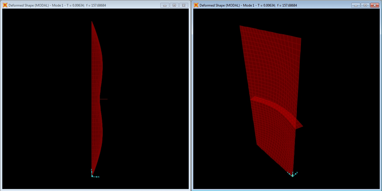
Mode shape with 1 - 2” x ¾” brace, mode 1 at f = 157.69 Hz.
A single centerline brace attempts to enforce the second longitudinal mode of the unbraced panel, but with insufficient stiffness to fully force an inflection point and the corresponding second longitudinal mode of the unbraced panel. Never the less, the natural frequency of the panel is significantly increased from the unbraced response at 114.1 Hz.
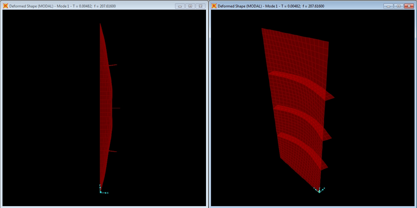
Mode shape with 3 2” x ¾” braces, mode 1 at f = 207.62 Hz.
The three brace configuration moves further from the matching the corresponding longitudinal mode of the unbraced panel, falling short of even the third longitudinal mode at 265.7 Hz. Once again, the natural frequency is substantially increased, above both the previous braced mode and the second longitudinal unbraced mode at 170.9 Hz.
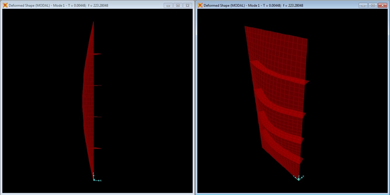
Mode shape with 4 2” x ¾” braces, mode 1 at f = 223.28 Hz.
We are now at the point where the need for additional brace stiffness is evident as the four brace configuration is barely able to generate noticeable local restraint at the brace points. This mode has a higher frequency than the three brace configuration, but falls short of the third unbraced modal frequency, showing behavior that is trending towards global rather than local restraint from the additional braces.
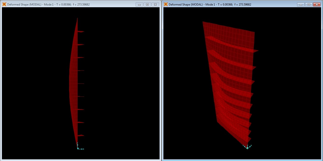
Mode shape with 9 2” x ¾” braces, mode 1 at f = 273.60 Hz.
The nine brace configuration effectively behaves as a global, higher frequency fundamental mode. The frequency is higher than that of previous four brace configuration, but just barely clears the frequency of the third longitudinal mode of the unbraced panel at 265.7 Hz.
Next, we will look at the deformation of the panel with various braces near peak resonance from the harmonic loading. The plots are all scaled at a consistent factor of 2500.
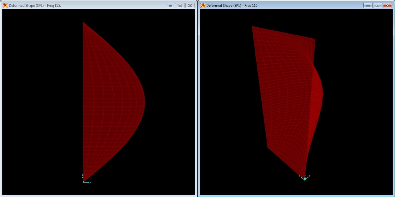
Deformed shape with no braces at f = 115 Hz.
The unbraced panel clearly shows deformation consistent with the corresponding fundamental mode shape.
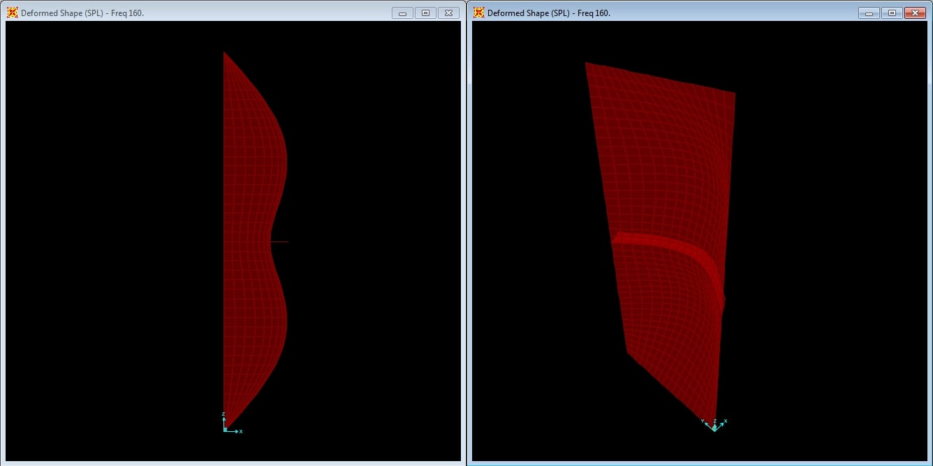
Deformed shape with 1 - 2” x ¾” brace at f = 160 Hz.
The deformation under harmonic load of the single brace configuration again matches the mode shape with the brace providing some localized restraint. Also, note the significant decrease in deformation compared with the unbraced panel.
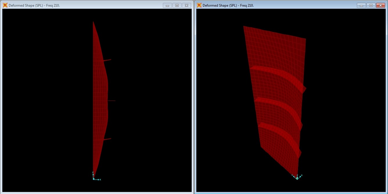
Deformed shape with 3 2” x ¾” braces at f = 210 Hz.
The trend is continued for comparison both with the corresponding mode shape and with the decrease in deformation from the previous brace configuration.

Deformed shape with 4 2” x ¾” braces at f = 225 Hz.
With an additional brace, the trend from local restraint behavior towards global restraint behavior continues to progresses from the previous case.
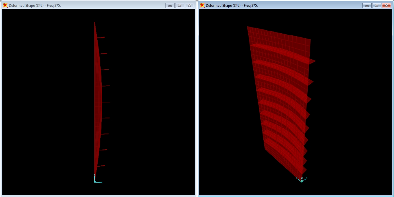
Deformed shape with 9 - 2” x ¾” braces at f = 275 Hz.
The effectiveness of the braces to locally restrain the panel continues to decrease with nine braces even as the global deformation is restrained further.
At this point, the behavior of the braced system is effectively that of the fundamental mode of the unbraced system, but with a higher frequency and reduced displacement, as shown in the following plots.
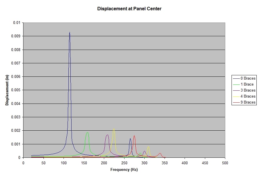
Displacement, panel center, for various numbers of 2” braces.
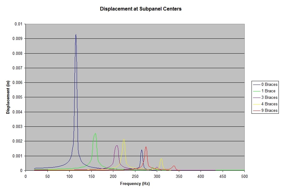
Displacement, sub-panel center, for various numbers of 2” braces.
The plots are based on displacement at the center of the panel or sub-panels formed between braces nearest the center of the panel.
Plotting the maximum displacement clearly shows both the decrease in displacement and the relative decrease in effectiveness of each additional brace with a constant stiffness.
There is also some shifting around of the relative effectiveness between different numbers of braces. This is another indication of the decreasing effectiveness of more bracing without increasing the stiffness of the braces as the system transitions from local to global behavior with mode shapes similar to the unbraced fundamental, but with increased frequencies and reduced displacement. This shifting of displacement amplitudes could easily be misinterpreted as the additional bracing is not effective, but it is only an indication of the transition that is occurring.
Loudspeaker Cabinet Bracing: Finite Element Analysis - Part II
To better understand what is happening, we will now explore the system behavior of the braced panel with stiffer braces. The previous braced panel models were each rerun with the 2 x ¾” brace replaced by a 4 x 1½” brace, which has significantly greater stiffness, resulting the following mode shapes and frequencies.
Keep in mind, that the increased mass and greater eccentricity of that mass from the plane of the panel will increase rotational effects on the panel and this will further complicate the modal behavior of the system. The additional complexity of the modal behavior also makes it more difficult to correctly interpret results with limited information from measurements.
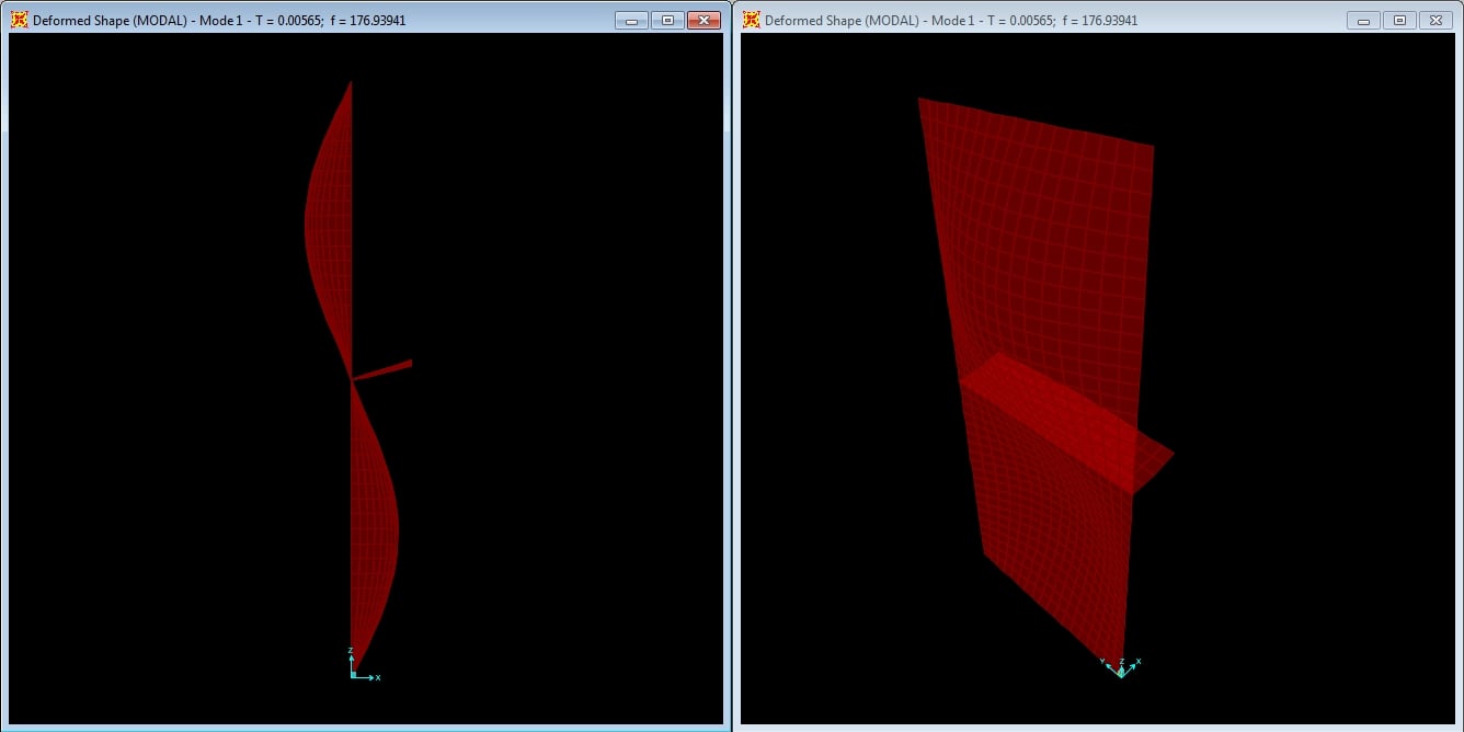
Mode shape with 1 4” x 1½” brace, mode 1 at f = 176.94 Hz.
The increased brace stiffness is able to fully force the first mode of the braced panel to the second mode of the unbraced panel. The resulting frequency is slightly higher than the corresponding unbraced mode, indicating the stiffness more than overcomes the additional mass. Also, note the slight rotational effect on the brace from mass eccentricity.

Mode shape with 3 - 4” x 1½” braces, mode 1 at f = 340.98 Hz.
With three braces at the increased stiffness, the first braced mode is forced nearly to the fourth unbraced mode. The inflection points are slightly shifted from the brace points, which is consistent with the somewhat lower natural frequency and is due to a combination of lower relative stiffness, additional mass, and the mass eccentricity.

Mode shape with 4 4” x 1½” braces, mode 1 at f = 384.18 Hz.
The four brace configuration approaches the fifth longitudinal mode of the unbraced panel, but falls short of the frequency with slight, but visible shifts of the inflection points from the braces.
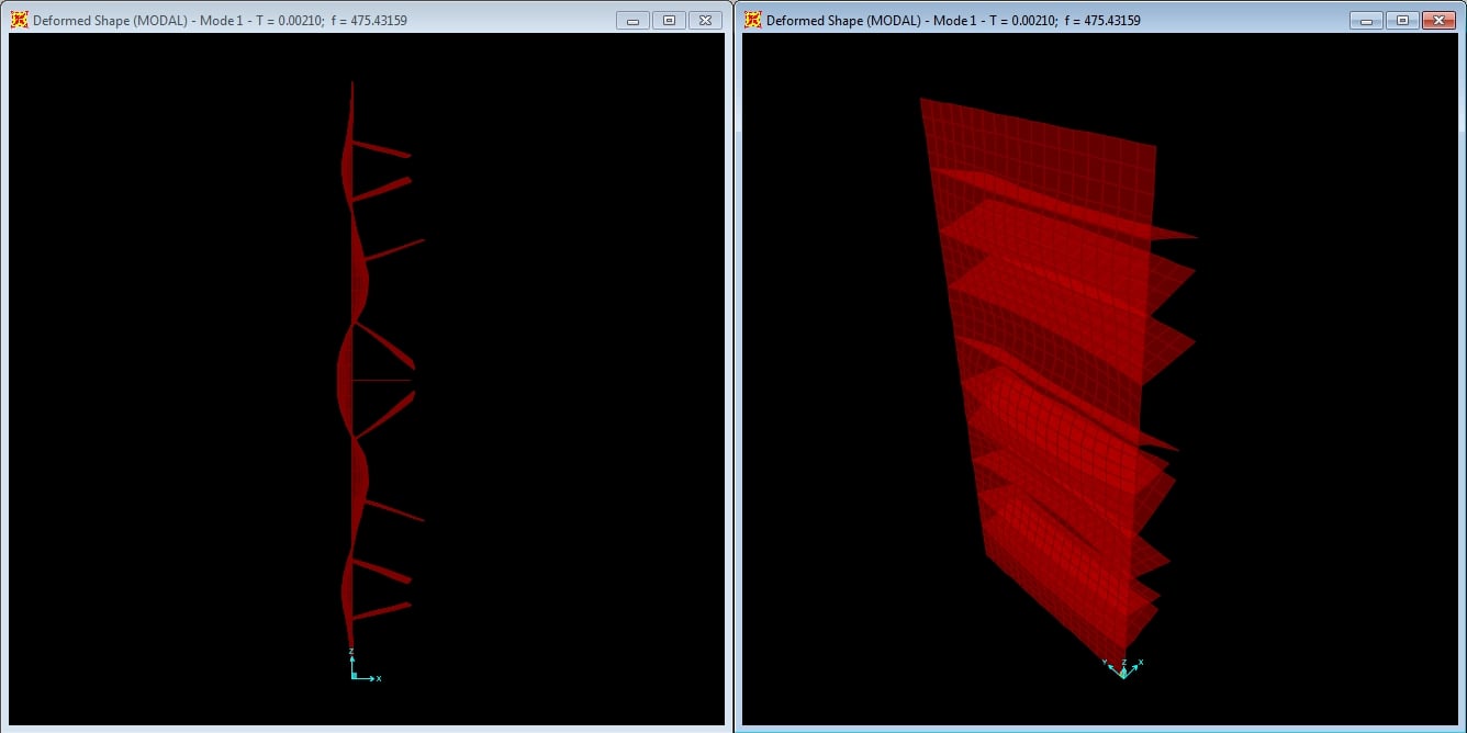
Mode shape with 9 - 4” x 1½” braces, mode 1 at f = 475.43 Hz.
Nine braces are only able to enforce a mode similar to the fifth longitudinal mode of the unbraced panel. Note that the frequency has increased considerably from the previous four brace configuration, although the modes are similar.
For comparison, we can also look at the unbraced panel with a 2¼” thickness, which uses a similar amount of MDF material to the nine brace panel above.
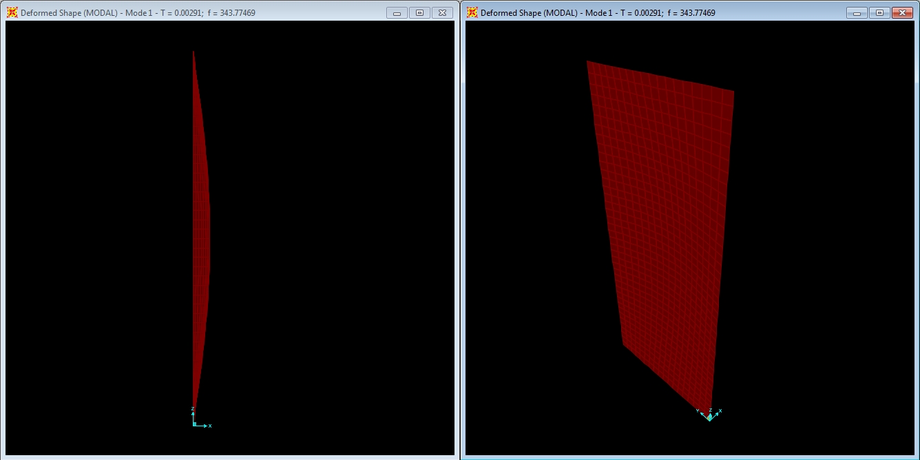
Mode shape with 2¼” thick panel, no braces, mode 1 at f = 343.77 Hz.
While the fundamental frequency is significantly higher than for the same mode of the ¾” panel, it is also significantly lower than the braced panel with a comparable amount of material. Also note the similarity of the shape to that of the nine 2” x ¾” brace system. The frequency is improved in this case, but at a cost of 50% more material.
Returning to the original ¾” thick unbraced panel, we will look at the 10th longitudinal mode that the nine brace configuration theoretically would induce with sufficiently stiff braces.
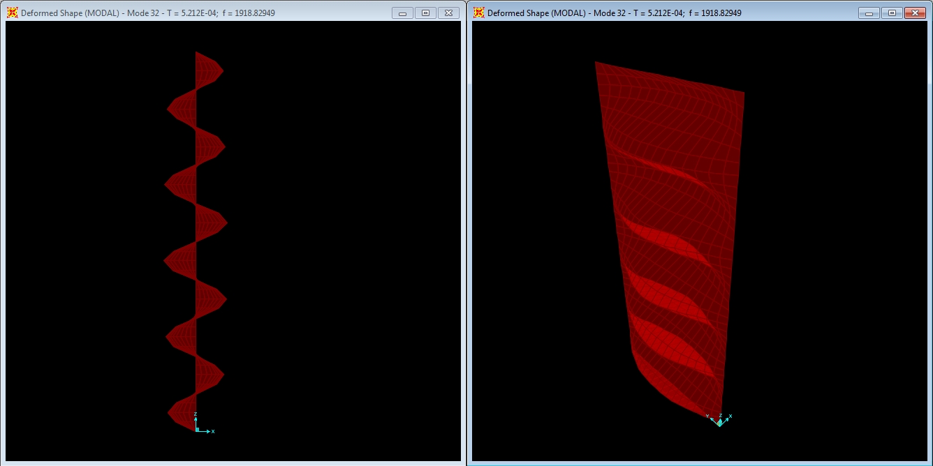
Mode shape with no braces, mode 32 at f = 1918.83 Hz.
To generate enough restraint to develop a mode this high, braces made of MDF would be prohibitively large and very likely not fit in the cabinet. At this point, it would make more sense to use a different material that is naturally stiffer, one with a higher modulus of elasticity. One possibility would be to use aluminum, which is common in other uses in the loudspeaker industry. With a modulus of 10,000 ksi, an aluminum brace would be approximately 17.2 times stiffer than a brace with the same cross sectional area made of MDF.
We will now look at the deformation of the braced panel near peak resonance from the harmonic loading. The plots are scaled at the previous factor of 2500.
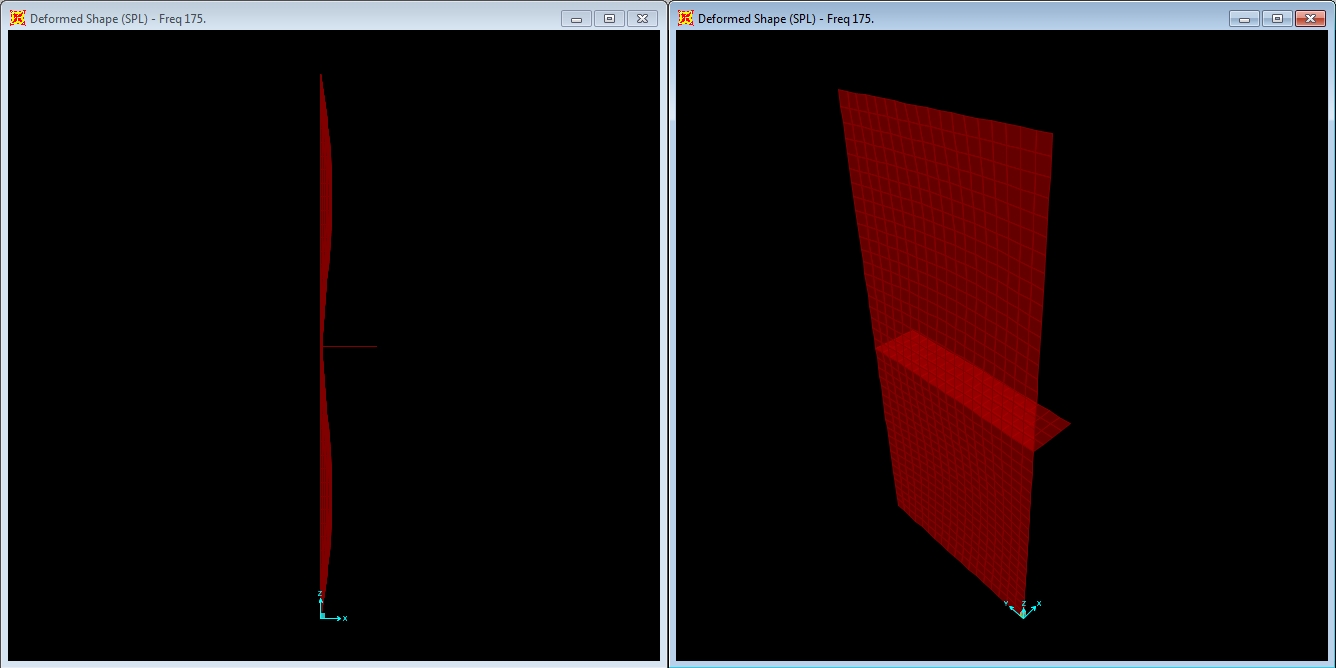
Deformed shape with 1 - 4” x 1½” brace at f = 175 Hz.
With a single brace, the resonant deformation is significantly depressed compared with the smaller brace. The brace is also stiff enough to approach the condition assumed for the calculations in the preceding section where the panel was assumed to not deflect at the brace location.

Deformed shape with 3 4” x 1½” braces at f = 340 Hz.
The deformed shape is almost completely suppressed at this scale, so the deformation will be plotted again at 40 times the previous scale, a factor of 100000.
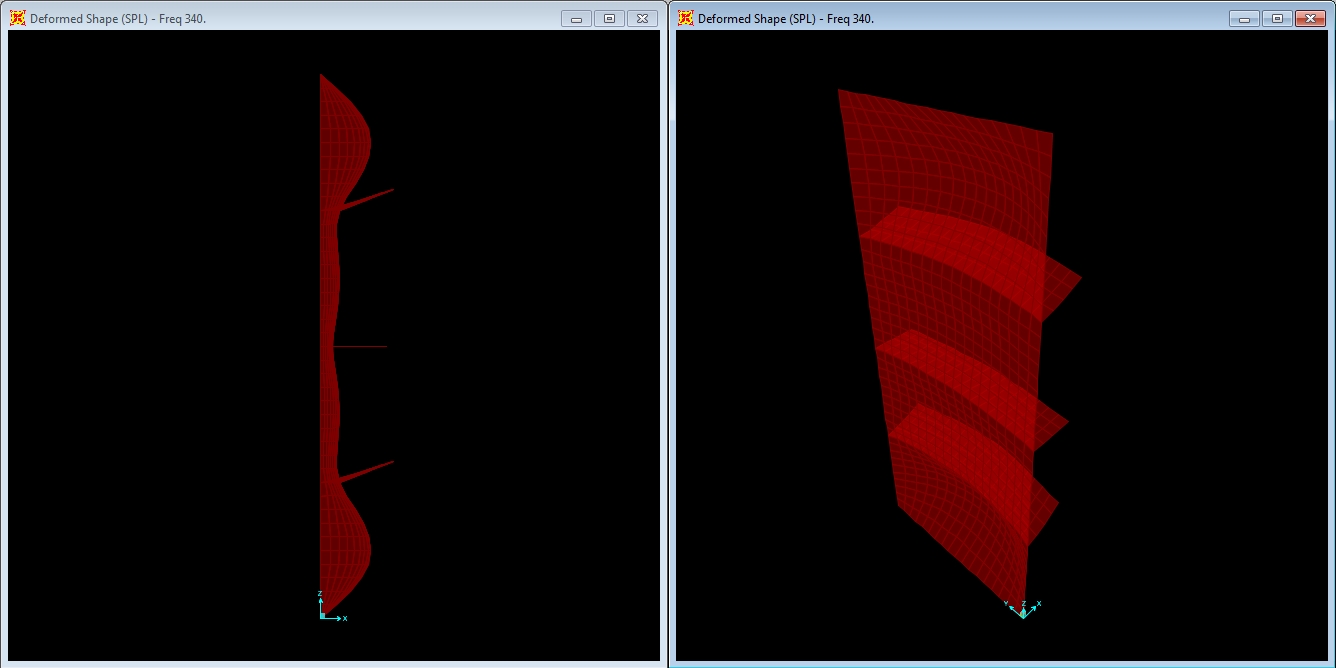
Deformed shape with 3 4” x 1½” braces at f = 340 Hz.
At ten times the previous scale, the restraint from the braces can be seen. The difference in the deflection of the outer sub-panels from the inner is due to the rotational restraint of the inner sub-panel edges from the adjacent panels, while at the outer edge there is no rotational restraint. This condition differs from the assumptions made in the previous section, but is captured in the more rigorous finite element analysis.
What also should become clear from this plot is that the point of measurement and comparison is important to proper interpretation of results. We have been using the sub-panel center point nearest the center of the overall panel. We will continue to do so for consistency, but what also should be clear is that any testing and measurement regiment used in prototyping loudspeaker cabinet vibration based on a limited number of measurement points could produce misleading results.

Deformed shape with 4 4” x 1½” braces at f = 385 Hz.
At the original 2500 scale factor, the panel deformation is not visible, but increasing the scale as before, we can see the deformation.

Deformed shape with 4 4” x 1½” braces at f = 385 Hz.
At the increased scale, the deformation shows visible restraint at the braces consistent with the fifth longitudinal mode of the unbraced panel.

Deformed shape with 9 4” x 1½” braces at f = 475 Hz.
The original scale factor does not show any noticeable deformation under load.
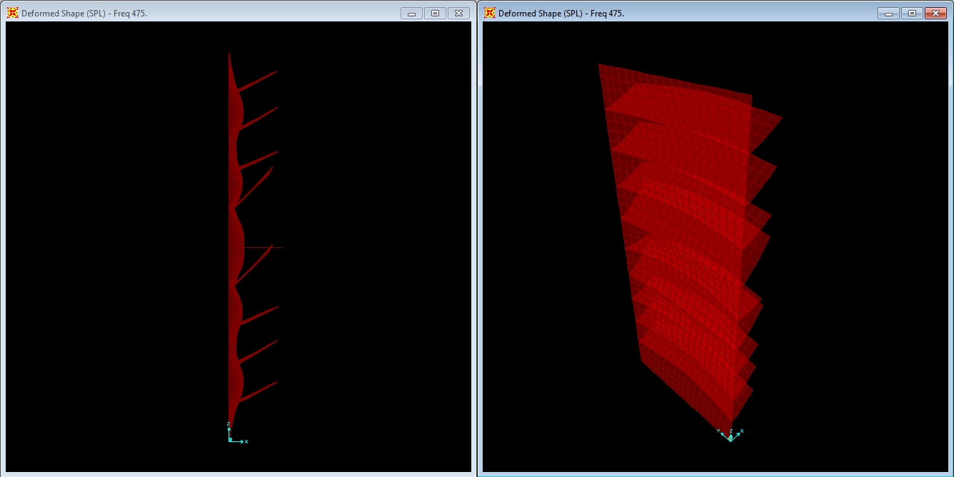
Deformed shape with 9 4” x 1½” braces at f = 475 Hz.
At the increased scale, deformation similar to the fifth unbraced panel longitudinal mode is visible. Note that restraint points occur near the second and fourth braces in from the panel ends, the same locations as in the corresponding mode shape.
As the number of the stiffer braces has been increased, we can see the reduced effectiveness in forcing modes that match the brace configuration, but now this transition occurs at a much higher mode number and frequency than with the less stiff braces. Using 2 inch deep braces, the system was only forced to the equivalent of the second unbraced mode, but with the 4 inch deep braces, the system is forced to the equivalent of the fifth unbraced longitudinal mode and the corresponding frequencies are nearly doubled.
|
Unbraced Panel |
Braced Panel |
||||||
|
Mode# |
Longitudinal Mode |
Frequency (Hz) |
# of Braces |
Equivalent Longitudinal Mode - 2" |
Frequency (Hz) |
Equivalent Longitudinal Mode - 4" |
Frequency (Hz) |
|
1 |
1 |
114.1 |
|
|
|
|
|
|
2 |
2 |
170.9 |
1 |
2 |
157.7 |
2 |
176.9 |
|
3 |
3 |
265.7 |
3 |
1 |
207.6 |
4 |
341.0 |
|
5 |
4 |
397.8 |
4 |
1 |
223.3 |
5 |
384.2 |
|
8 |
5 |
566.5 |
9 |
1 |
273.6 |
5 |
475.4 |
From the results listed in this chart, it is clear that not only adding braces, but also adding adequately stiff braces is necessary. Increasing the stiffness of the braces further would continue to push the system into higher modal behavior. Braces that are inadequately stiff effectively result in what can be referred to as a partially braced system, where the bracing can enforce a higher mode number, but not a mode that is as high as the bracing geometry would suggest.
Ultimately, if the stiffness of the bracing is inadequate to force any mode higher than the corresponding fundamental mode of the unbraced system, the system can be referred to as an unbraced system. While braces are geometrically present, the results are similar to an unbraced system with increased global stiffness such as just thickening the panel.
Loudspeaker Cabinet Bracing: Finite Element Analysis - Part III
Plotting the deformations of the various 2 x ¾" brace configurations with the 4 x 1½” brace configurations under the harmonic loading will allow us to compare the resulting behavior.
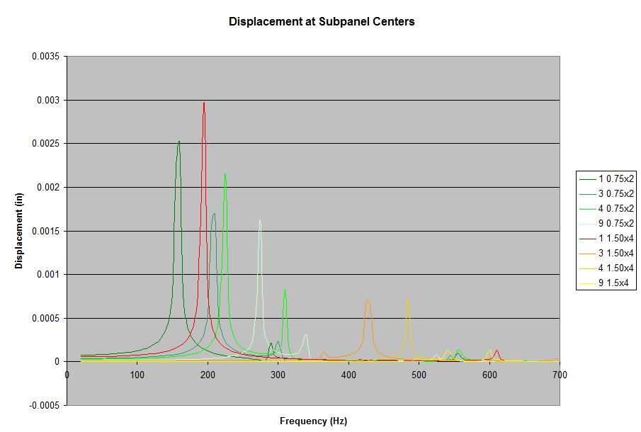
Displacement, sub-panel center, for various numbers of braces.
Reviewing the results in the plot, the general trends of increased cabinet frequency and suppressed resonant displacement is clear. Going to the four inch deep braces in a clear improvement for all cases except for the single brace. The transition to where the braces are not stiff enough to force a higher mode is evident in the flattened peaks for three and four of the deeper braces, but suppression of resonant amplitude continues to the nine brace configuration.
For the single four inch brace, not only is the resonant amplitude slightly increased, but also the peak is not quite at the frequency of the first mode. Investigating the second mode, we can see the source of the discrepancy in the mode shape with a closely spaced frequency and both halves of the panel in phase with a shape matching the deformation under load, which would be easier to excite. The shape and close proximity of the second mode mask the first mode and produce the greater resonance.
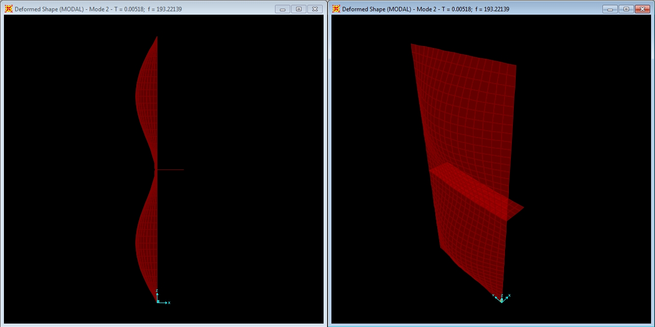
Mode shape with 1 4” x 1½” brace, mode 2 at f = 193.22 Hz.
Focusing in on the nine brace configuration, we can look closer at the displacements and compare them with the results of just thickening an unbraced panel.
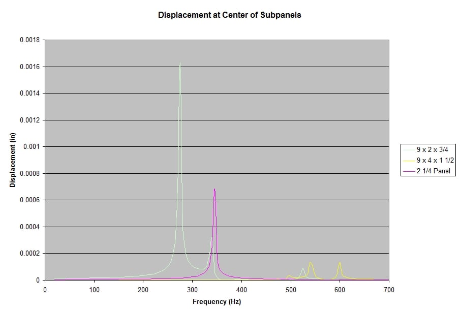
Displacement, sub-panel center, for thickened panel versus nine braces.
Comparing the nine 2 x ¾" braces to both the 2¼” thickened panel and the nine 4 x 1½” brace configuration, we can clearly see the vast improvement to resonant displacements from the additional stiffness. We can also see that just thickening the panel with an equivalent amount of additional material as the 4 inch deep brace configuration does not produce results that are as effective. This is due to the higher modal behavior of the braced panel.
At the increased plot scale, we can also see that four inch brace configuration has some unusual features. The first mode does not produce the highest resonant peak, which occurs at the second and third peak with similar levels.
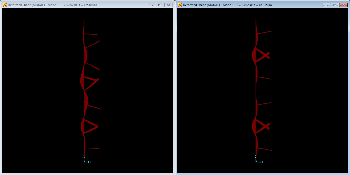
Modes 2 at 475.68 Hz and mode 3 at 481.15 Hz.

Modes 4 at 482.49 Hz and mode 5 at 485.81 Hz.
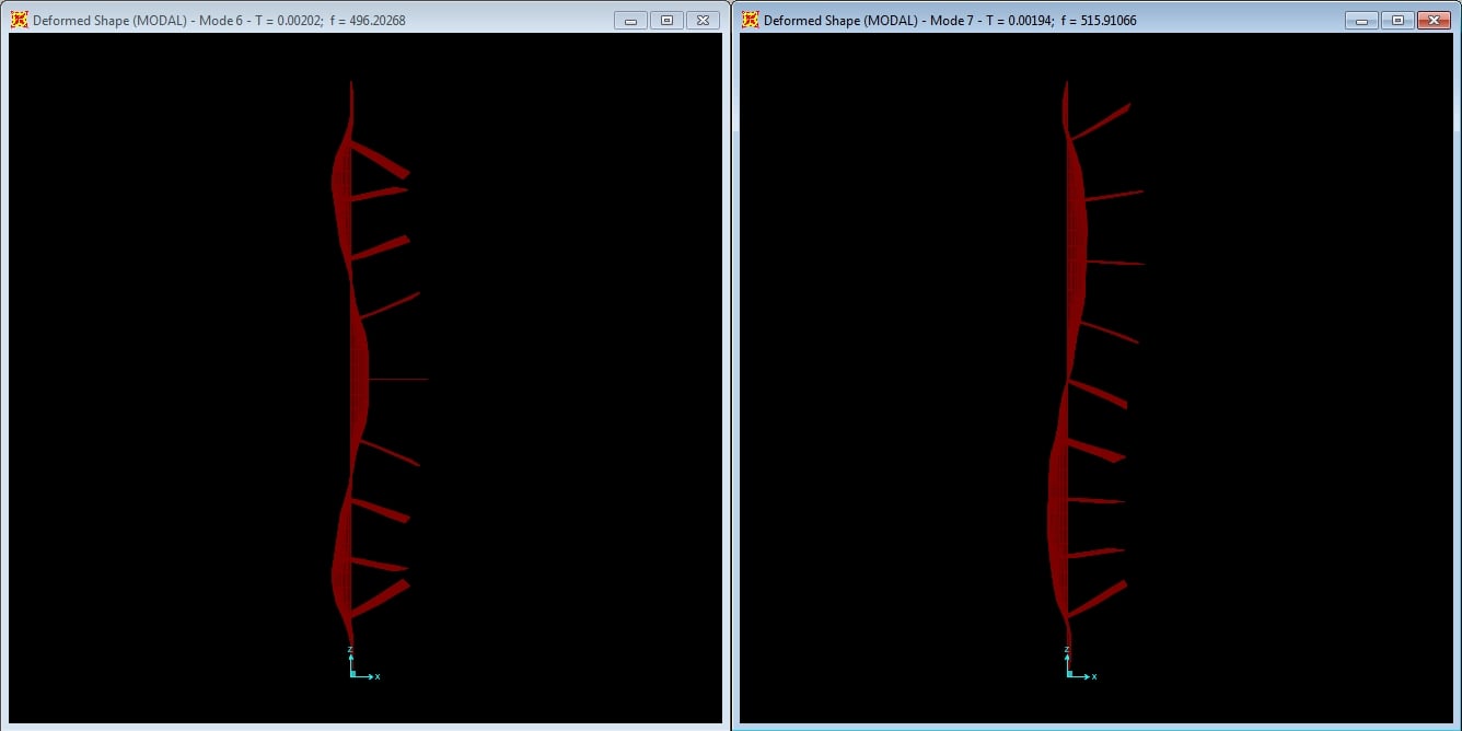
Modes 6 at 496.20 Hz and mode 7 at 515.91 Hz.
Reviewing the modes for this condition, we find that the first six modes form a cluster between 475 and 496 Hz flipping back and forth between four and six half-wave mode shapes. These clustered modes partially cancel each other out, producing the reduced first peak.
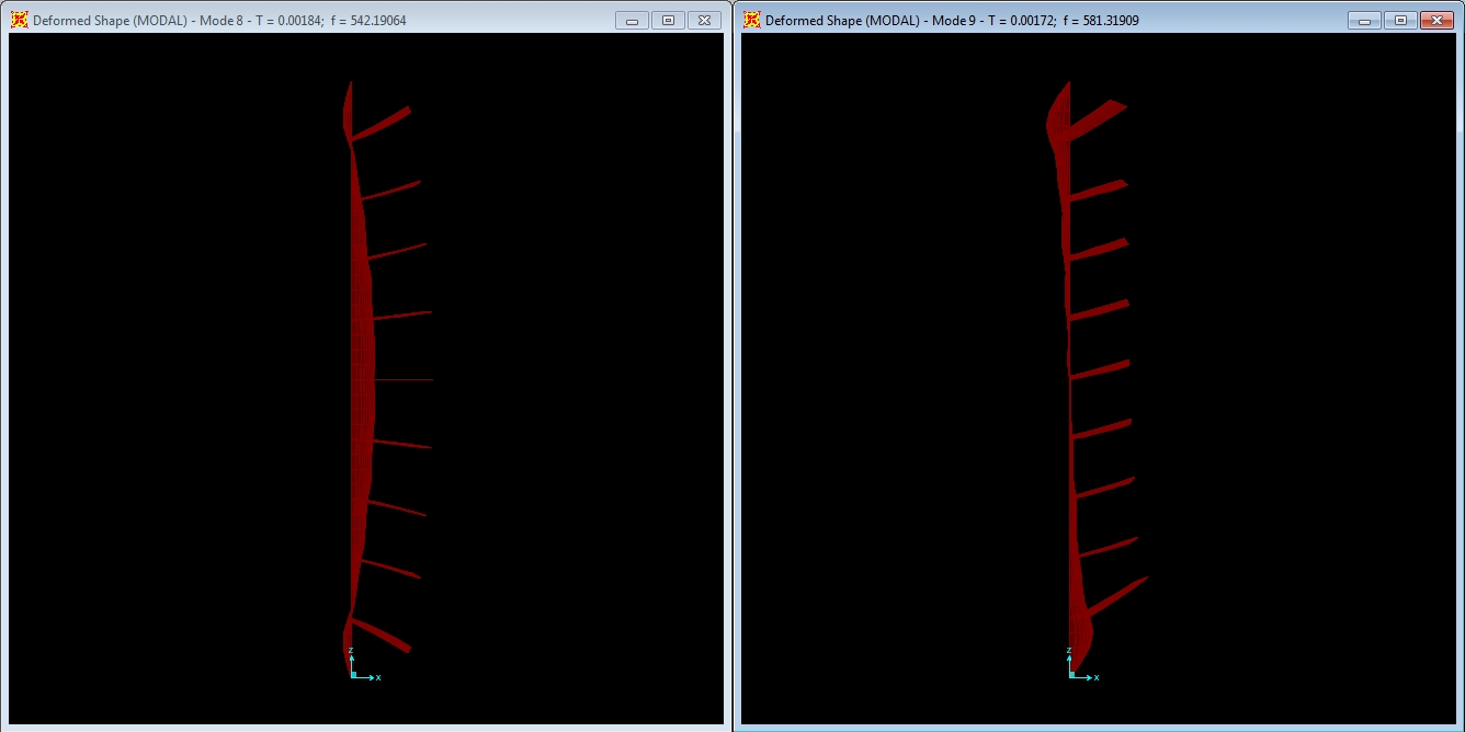
Modes 8 at 542.19 Hz and mode 9 at 581.31 Hz.
The modes start to spread out by the seventh at 516 Hz and eighth at 542 Hz, which is at the first of the two larger peaks.
What should become clear from the discussion is that the modal behavior of the panel and braces is complex. A full analysis of a complete loudspeaker cabinet system would introduce additional complexity to the results in order to obtain more accuracy, but the trends seen here would still be present in the behavior.
Loudspeaker Cabinet Bracing: Conclusion & References
 Controlling vibrations of loudspeaker components beyond the
drivers is essential in maintaining musical fidelity in sound reproduction due
to the relation between vibration and sound pressure. Panel bracing can be an effective means of minimizing unwanted
vibrations in a loudspeaker cabinet, but understanding the underlying mechanics
defining the system behavior can make a given bracing scheme more of less
effective.
Controlling vibrations of loudspeaker components beyond the
drivers is essential in maintaining musical fidelity in sound reproduction due
to the relation between vibration and sound pressure. Panel bracing can be an effective means of minimizing unwanted
vibrations in a loudspeaker cabinet, but understanding the underlying mechanics
defining the system behavior can make a given bracing scheme more of less
effective.
- Additional bracing added to a cabinet system will improve the dynamic performance to a greater of lesser extent, depending on the stiffness of those braces.
- Modal behavior of the system rapidly becomes complex and difficult to interpret as additional braces are added to a system. The complexity of the modal behavior will be increased further when including the entire cabinet system.
- Braces added to the system must be sufficiently stiff to develop inflection points at the braces that induce higher modal behavior to be fully effective.
- As more braces are added to a system, all of the braces need to be increased in stiffness to remain fully effective at controlling the resulting behavior.
- When braces are not stiff enough to induce modal behavior consistent with the brace geometry, the system will start to transition to lower modal behaviors, and ultimately will behave similarly to the fundamental mode of an unbraced system.
- Because of the complexity of the modal behavior, limited measurements when testing a prototype cabinet for vibration can produce misleading results.
Simply adding more braces to a cabinet may not be the most effective way to reduce vibration if those braces are not stiff enough to force higher modal behavior in the panel under time varying loads, such as music.
Regardless, increasing the stiffness of a cabinet is always beneficial in reducing the resonant peaks that occur under dynamic load. There really are no circumstances under which a loudspeaker engineer would want to lower the resonant frequency of a cabinet by reducing the number of braces if the goal is to improve fidelity. Doing so will simply cause higher amplitude resonances within the operating frequency range of the drivers, which will lead to higher audibility from a less, stiff cabinet and hence coloration of the sound. The design goal of any high fidelity loudspeaker should be to have an enclosure that is as stiff as possible to house the drivers and minimize sound colorations from unwanted panel resonances.
References
Timoshenko, S.P. and S. Woinowsky-Krieger: Theory of Plates and Shells, 2nd Edition, McGraw-Hill, 1969, Reissued 1987.
Young, Warren C.: Roark’s Formulas for Stress & Strain, 6th Edition, McGraw-Hill, 1989.
Imrak ,C.E. and I. Gerdemeli: An Exact Solution for the Deflection of a Clamped Rectangular Plate under Uniform Load, Applied Mathematical Sciences, Vol. 1, 2007, no. 43, 2129 – 2137.
Clough, R.W., J. Penzien: Dynamics of Structures, 2nd Edition, McGraw Hill 1993.
Computers and Structures: CSI Analysis Reference Manual for SAP2000, ETABS, SAFE, and CSIBridge, Rev. 4, Computers and Structures, Inc, 2010.
Fahy, F. and P Gardonio: Sound and Structural Vibration, 2nd Edition, Academic Press, 2007.
Professionally, David engineers building structures. He is also a musician and audio enthusiast. David gives his perspective about loudspeakers and complex audio topics from his mechanical engineering and HAA Certified Level I training.
View full profile