
Loudspeaker Power Ratings: What's the Deal Part II?
Back to Future
SUMMARY OF PART ONE - Power handling limitations result from both thermal and mechanical issues. Power consumed by a loudspeaker is traditionally estimated by assuming the speakers resistance is invariant with frequency, time, and temperature and is purely resistive. All these assumptions are false, and lead the industry to publish figures which are unrealistically high pleasing both the buyers and sellers who are engaged in a never ending competition to offer the greatest power handling. Standardized power testing signals are unrealistically compressed, allowing for easier measurement and data collection, but compromising the usefulness of the data gathered. Standardized power test signals are not uniformly adopted by manufacturers and differences exist between standards in wide usage. Worst of all, some manufacturers ignore standards and testing, and simply either estimate the power handling or in some cases simply publish numbers they believe will boost their sales without regard to the truth. Manufacturing a speaker which will have the best power handling for the resources employed requires an intimate knowledge of several factors which are sometime pulling the designer in different directions at once. Sometimes issues unrelated to engineering influence design and the resultant products, often to the detriment of optimum performance.
Check out our recent YouTube video discussion on matching amplifier power to loudspeakers.
YouTube Discussion: The Truth about Matching Amplifier Power to Loudspeakers
PART TWO – POWER HANDLING OF LOUDSPEAKERS
The reason we put more power into a speaker is because we expect more output as a result. In part two we will discuss compression, an effect that means while we put more power into the speaker, it is failing to give us a proportional increase in acoustic output because of thermal and/or mechanical limitations.
At the conclusion of part one, we illustrated how a loudspeaker whose DC resistance was 6.2 ohms (a very common and realistic figure for a typical 8 ohm loudspeaker) would go to 12 ohms at 500 degrees F, or 260 degrees Celsius, not an unrealistic figure to encounter in the world of professional audio where use of 5000 watt amplifiers are not uncommon. (5000 watts is about 6.78 horsepower, so this is considerable considering you are attempting to use all this power in a VC only 4 inches (100mm) in diameter and perhaps 0.5” to 1.0” in height, often weighing less than 50 grams (under 2 ounces). At this point, the actual power delivered to the speaker is only 50% of the apparent power, calculated by assuming the nominal impedance remains unchanged. At this temperature, the speaker is likely to fail, and the low frequency (Thiele-Small) parameters are also completely different than what the speaker was prior to overpowering. Let's take a look and see what the heating alone will do.
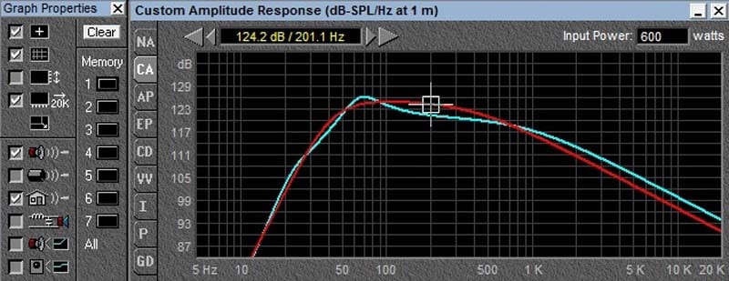
12 ohm vs 6 ohm at same power
As we can see from the comparison curve above, the sensitivity of the speaker is diminished by 3db at elevated temperatures, so that the actual output is less than what we would expect. As shown, we have kept the power constant at 600 watts, which means we had to raise the voltage by 1.414 times to insert the same power. In practice, it is doubtful that you would be able to do this, as your amp would simply run out of voltage. In that case, assuming there was no more available voltage, the loss would be much more severe as shown below:
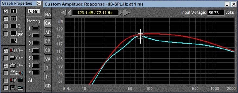
12 ohm vs 6 ohm at same voltage
In this case at 200 Hz we actually lose 6db, 3db to sensitivity loss and another 3db to loss of power (we only pull half the current, and P=V*I).
Instead of being able to consume the power applied as voltage times current, the heating voice coil tends to self limit the current flowing through it, in effect compressing the musical signal and lowering the dynamic range of the recording, in much the same way an amplifier running into clipping will do.
So, clearly without a knowledge of the thermal compression occurring We cannot know what the actual power consumed is, nor can we predict what the acoustic output will be based on the published 1 watt sensitivity of the speaker, and the available amplifier power. Some companies DO publish compression data, and make it available to the system designers. JBL is one such example, and below are 3 links to data sheets that include power compression information.
http://www.jblpro.com/pub/obsolete/4645b.pdf
http://www.jblpro.com/pages/pub/components/2206.pdf
http://www.jblpro.com/pages/pub/components/2226.pdf
Let's go back to the first equation introduced in part one:
Force (Newtons) = B (Tesla) * L (Meters) * I (Amperes)
The force on the voice coil is proportional to the sound PRESSURE level. A doubling of force results in a 6db increase, which is a doubling of sound pressure level (SPL). If the amplifier runs out of voltage or current, then the current (amperes) is limited reducing the resultant SPL. What about the other parameters, B & L (Magnetic Force times the length of conductor in the field).
The Mechanics of Speaker Clipping
Speaker “clipping” like amplifier clipping will occur when the excursion required to reproduce the signal results in the VC being propelled OUT of the magnetic field, reducing the motor force (B*L). What would cause this? Just like an amplifier has a physical limit for its available voltage or current, a loudspeaker has a physical limit to its available travel in either direction from the static position. This parameter is known as Xmax. If the VC travels OUT of the magnetic gap, then the resultant product of (B*L) is reduced so that the Force acting on the VC and in turn the diaphragm, and hence the air it is coupled to is reduced. In short, the speaker is running out of excursion capability, so it is self limiting in the amount of available output. This effect is present in all speakers, but especially so with subwoofers. To see why this is so, let's review the following graph.
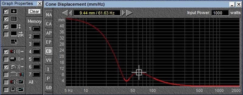
1000 watts displacement vs frequency
As we can see, as the excitation frequency is lowered, the excursion increases dramatically. To have the same output at a frequency twice as low, the speaker cone needs to move 4 times the distance. (This is a rough approximation which is changed by the speaker and box damping as well as the port tuning). The null at 40 Hz is the reduction in cone excursion caused by the venting of the box. The change in brightness of the line is the program rightly indicating this prediction is based on things staying the same, but they cannot because above 5.5 mm, the amount of Xmax available from the speaker in this example, this VC jumps out of the gap. (The change in brightness is telling the designer, if you want to put that much power into this speaker box system, you had better use a longer VC or suffer the consequences of high distortion and quite possibly speaker self-destruction).
Another issue affecting the ability of our speaker to convert the input power to acoustic power revolves around the drop in motor force (B*L) that occurs as the VC moves off the center position. (Since B is the strength of the magnetic field, if the VC (L) is moving out of that magnetic field, the product of the two (B*L) is going to be reduced). This will lessen the damping available on the speaker and change the way it moves as a function of frequency. Unlike electrical currents, where we can use conductors and insulators, with a magnetic circuit the “conductor” is a short air gap. Unfortunately, the area just above and below is just a slightly further path, so the magnetic lines of force do not suddenly fall off to nothing, they lessen slightly making the definition of the actual magnetic gap less definite and as small as we would like. This means our B*L does not suddenly drop to zero, so there is force (B*L*I) acting to push the speaker even after the VC completely leaves the area of most intense magnetic field. See the illustrations below:
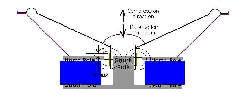
small speaker model
Loudspeakers & Power Ratings: What's the Deal Part II Continued?
As we can see from the half section view of the loudspeaker, the dimensions of the magnet, voice coil and steel magnetic parts (which complete the magnetic circuit) will set the amount the speaker can move before it collides its own parts together, sometimes called bottoming, a mechanical affect not related to the drop off in (B*L).
BL reduced from 19 to 12
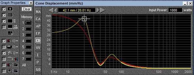
Let us look at an example where the B*L falls off by about 37%, a very modest and realistic figure for a VC coming slightly out of the gap. In the graph above, the orange line represents a speaker with a BL product of 19 T-M versus the yellow line which is 12 T-M (37% less). As we can see from this model, we need the speaker with the 12 TM to move 42mm (1.65 inches off center in each direction) if we attempt to drive it with 1000 watts at 20 Hz in a box tuned at 40 Hz. This would require a VC on the order of 100 mm in height (not diameter) but VC height. (See diagram below)
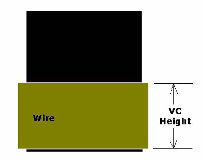
Voice Coil
A typical VC is around 1 inch in height, and has perhaps 8-10 mm (about 0.35 inches) of excursion available by virtue of its height exceeding the top plate thickness. (We call this overhang). So what will happen if we attempt to power 1000 watts into this typical speaker at 20 Hz? In all likelihood it will break by smashing its parts together (bottoming) long before the VC even has a chance to get hot.
At the outset, I said there were two ways to destroy a speaker, thermally or mechanically. The mechanical limits to what a speaker can do must be considered if one is to obtain a picture of “how much power can it handle?” In fact, once we start making subwoofers with VC diameters of 3 inches or more, the likelihood of seeing a thermal failure falls way off relative to the likelihood of seeing a mechanical failure. Some conventional power handling tests use signals from the speakers resonant frequency up to a frequency 10 times as high, (The AES standard is an example). This will give us little indication of how much power a subwoofer can handle in real life, when it is rarely used above 120 Hz. 400 watts is not 400 watts when it comes to power handling. Unless you know the details of the signal used, then you know little about what the speaker can do. In part one, I said I would show you how we can take a speaker with a power handling of 500 watts and make it handle 1000 or break with 100 watts. Here is an example.
Speaker Failure Example at Various Power Levels
Let us say we have a woofer which we know when excited with pink noise, set from 50 to 500 Hz can handle 500 watts before it will burn. Let it be a given.
We know from the earlier example at middle and high frequencies the excursion is small and as we go lower, the excursion increases dramatically. If the signal used is placing its power across the full bandwidth of the audible spectrum in varying amounts (as it should be) then this signal will most likely burn the VC before it breaks the speaker. Suppose now, we go back to the earlier example of the vented speaker tuned at 40 Hz and drive it at 20 Hz.
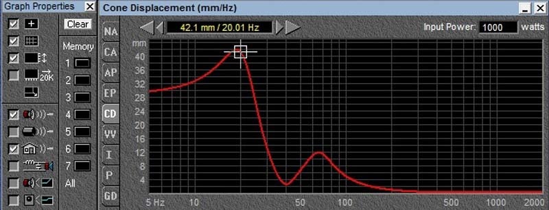
1000 watts @ 20 Hz
We notice that at 20 Hz, the excursion of this speaker is predicted to reach 42 mm at 1000 watts. I said predicted, because the program running the model assumes (as most of these programs do) that the speaker can actually move that far without destroying itself. Well, it cannot. In short, we are asking this speaker to destroy itself. Suppose instead of using a continuous signal of 20 Hz, we simply use a tone burst. Ten cycles on, Ninety cycles off. That means for 90 percent of the time, the power applied is zero watts. Since we need to break this speaker with 100 watts, we will make the tone burst (during its short duration) 1000 watts. Divide that by 10, and this averages to 100 watts RMS over the course of the power test (which is hours long). Since the crest factor of a single frequency continuous tone (sine wave) is 3db, and the signal is 1000 watts RMS (for 10% of the time) the peak power is 2000 watts, and the RMS is 100 watts, so the crest factor (ratio of peak to RMS power) of this test is 13 db. This crest factor is not standard or similar to power test signals at all, but it is not unlike music either. The spectrum however, is definitely unlike music, and designed in concert with the crest factor to BREAK this speaker.
Choosing the Test Signal
OK, we have proven we can be cruel, now let’s be kind to the speaker and give it a really big number (we want to make the boss and his customers happy). Instead of using a standard such as the EIA RS-426A spectrum, (Circa 1980, and this has been replaced by standard “B” which has more LF energy) let's use simple white noise (that stuff you hear in between FM radio stations or when your TV station goes out.)
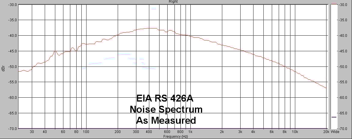
EIA RS426A Measured Noise Spectrum
Editorial Note on White & Pink Noise
White noise is so called because it is like white light in that it has equal energy per unit hertz. Pink noise is white noise RED shifted (so now it is pink). When you red shift a spectrum, you bias it toward low frequencies, as in a source (like a train) which is moving away from you so that its motion increases the distance between the sound pressure waves, making the sound lower as the source moves away from you (Doppler shift). Pink noise has equal energy per octave, so the energy from 100 to 200 Hz is equivalent to the energy from 200 to 400 Hz White noise on the other hand, will have twice the energy (+3db) from 200 to 400 Hz, than it contains from 100 to 200 Hz
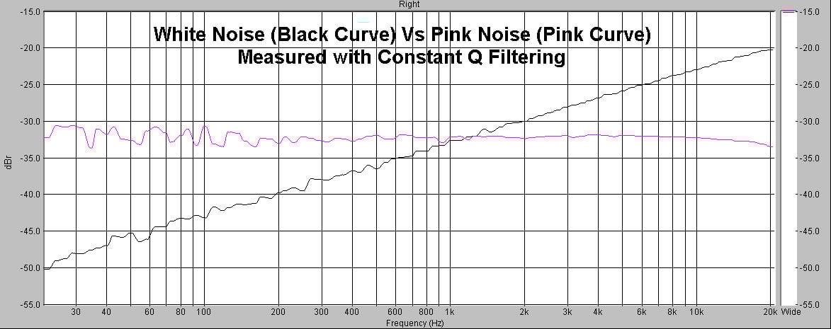
White Noise vs Pink Noise
So, if we suddenly use white noise to test a woofer, and we let the frequencies go from 20Hz to 20KHz, half of the energy is contained above 10kHz where the speakers Impedance is VERY high, and therefore the current drawn by the speaker is VERY low. Therefore the actual power dissipated in the speaker (as opposed to apparent power which calculates power into the nominal impedance) is also VERY low. Let's consider the woofer modeled below, with a typical 2 millihenry VC inductance.
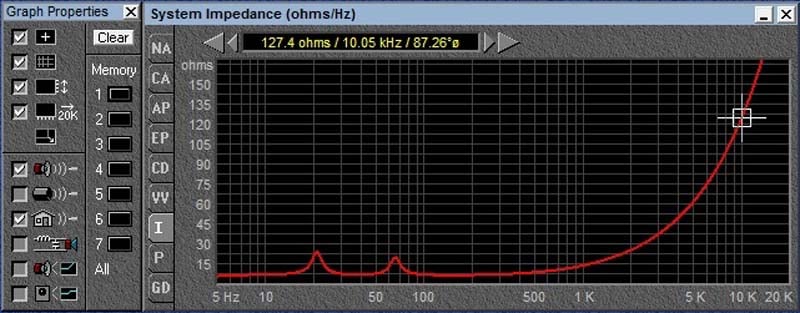
Impedance Full Range
As we can see from the Impedance magnitude graph, by the time we are at 10kHz, this speaker is already at 127 ohms. The current it is drawing is less than 7% of what it would were it actually 8 ohms (8/127 = 0.063). Since 50% of the power of this signal is actually above 10 KHz, the actual power delivered is far far less than what we would calculate into the nominal load impedance. Hence the apparent power handling is far greater than in fact the real power dissipated in the speaker. Using white noise and calculating power handling with the nominal impedance will yield a figure far greater than the 500 watts determined with EIA standard noise.
If you are asking well, who does this? The answer is no one. If the manufacturer is going to inflate his number, he likely will NOT ask engineering to go through this kind of exercise, they will simply make something up they believe is plausible and necessary for them to sell the product. The point I want to stress here is that without a knowledge of the test signal used, THE POWER HANDLING NUMBER IS MEANINGLESS!
without a knowledge of the test signal used, THE POWER HANDLING NUMBER IS MEANINGLESS!
Bass is a large signal, not a small signal phenomenon. The lower you go, the more power you need. As we go to lower and lower frequencies, our hearing becomes less and less acute. The result is as we go to lower and lower frequencies, we have less available dynamic range in our brains between the perceived low frequency, and the point at which it becomes painfully loud.
The result of this is while practically all amplifiers go down to 20Hz, very few speakers can reproduce it without producing more harmonic distortion than low fundamental frequencies. If you are pushing a compliant (soft suspension) speaker in a vented box well below the box tuning frequency (this is no different than playing it in free air) you will just end up producing lots of distortion, or simply break the speaker.
OK, this all makes some sense you say, but where is the proof? Why it is in part three of course. Stay tuned for some examples to back up the theory.
About the Author
Paul is currently President of his own Audio Consulting company, Procondev, based in Downey California, in Los Angeles County. He is actively seeking new clients and can be contacted by email by writing papollonio@yahoo.com