
Epique CBT24 Loudspeaker Designer Note by Don Keele
I want to thank James Larson for sharing a preview of his CBT24 review with me. I am speaking here as the designer of the CBT24 and not as a spokesman for Dayton Audio/Parts Express, the seller of the system. They have not seen my response in this designer note.
I didn’t change one word of his review but did make suggested revisions in two areas: one concerning the coverage of the CBT24 with added figures and the other concerning the inherent power roll-off of circular-arc loudspeaker arrays and the design of a special driver for the CBT24 that partially compensates for this roll-off.
I truly realize the massive amount of effort that has to go into a loudspeaker review like this having been the chief loudspeaker reviewer for the now-defunct Audio Magazine in the 90’s. He is to be commended for his efforts. I much appreciate the opportunity to chime in here in a designer’s note to explain the origins of the CBT24 and to share some additional measurements.
The CBT24 came a about in an attempt to greatly simplify the complexity of the Parts Express two-way CBT36K kit system which is a very challenging kit to put together! The CBT36 has been marketed since early 2012. This array utilizes 72 closely-spaced very-small dome tweeters in addition to its 18 each 3.5” mid -bass drivers. I thought it would make sense to create a less-expensive much-simplified one-way system using only wide-range direct-radiator drivers without tweeters.
However, when I first considered this design I was very apprehensive that eliminating the tweeters would actually work! But it did!
I’ve been preaching for years that the drivers in a properly-designed CBT array need to be spaced at no more than about one-half to one wavelength apart at the highest frequencies to minimize chaotic and rough high-frequency response.
Yes, the CBT24 exhibits chaotic and rough response above 8 kHz, but from a subjective standpoint it doesn’t seem to matter much! The magic of a CBT array is its very broad and even coverage at all locations in front of the array even if the response is erratic at high frequencies. It’s essentially uniformly erratic everywhere and as a result still comes across as sounding and imaging extremely well.
Listening to the CBT24, I was surprised that subjectively I was hardly able to hear any chaotic and rough high-frequency problems even with pink noise at many different locations in front of the system. This design theoretically shouldn’t work very well, but I was pleasantly surprised!
The roughness at any one particular location averages out at the many other locations making the system sound quite good overall, believe it or not. Just judge by Larson’s very positive comments in the listening section of the review, and listen for yourself if you have a chance.
The CBT loudspeaker technology is very well documented in a series of 17 technical papers I’ve authored or coauthored starting in 2000. All these papers are available from the Audio Engineering Society (AES) E-library which is free for AES members. I’d also like to suggest another easily accessible source for CBT information and technology in a nine-part YouTube video my son and I created called the CBT Chronicles.
Side comment: You’re welcome to skip over the rather-pedantic first parts of the video (Parts 1 - 5)with that crazy Don Keele lecturing about CBT technology and skip directly to the real-time measurement sections (Parts 6 – 9) which compares the coverage with a conventional well-designed three-way system against the CBT36. Highly worthwhile to take the time to view this!
One area that I want to amplify in this designer note is the vastly superior vertical coverage of a CBT ground-plane array as compared to conventional loudspeaker systems. James Larson was only able to include a small part of his measurements on the CBT24 that he accomplished due to space considerations.
Here I have added a series of measurements of a pre-production CBT24 that I accomplished that illustrates the extremely-well behaved vertical coverage of a CBT array. These measurements were not measured anechoically, like the excellent outdoor measurements that James Larson accomplished, but were run in my church’s large-metal-building family center using windowed-measurement techniques.
The following response measurements illustrate the excellent vertical magnitude/phase coverage of the CBT24 not in the conventional manner as a series of responses versus angle but in a series of responses versus height at a location very close to the front of the array. A CBT array has very uniform coverage and response at all points in front of the array including near-far, up-down, and right-left. A CBT ground-plane array easily passes the typical stand-up sit-down test with flying colors but also sounds great for people lying on the floor as well.
These tests are straightforward, unmodified, and honestly illustrate even the warts of the CBT24. The tests were run with the system placed on an acoustically-reflective tiled floor and measured at a series of six vertical heights in the range of 0.25 m up to a height of 1.5 m even with the top of the CBT24.
The response graphs illustrate the very uniform magnitude and phase responses of the system up to about 5 kHz at all these heights. At higher frequencies, the response becomes increasingly erratic, but as pointed out above is “uniformly” erratic at all locations in front of the array.
The magic of a CBT array is its very broad and even coverage at all locations in front of the array. The roughness at any one particular location averages out at the many locations making the system sound quite good overall.
The measurements are illustrated in the following six figures. Please refer to the figure captions for detailed descriptions. All the measurements were taken with the Dayton Audio measurement system with a “Blended” gate width of 5 ms and 1/12th-octave smoothing.
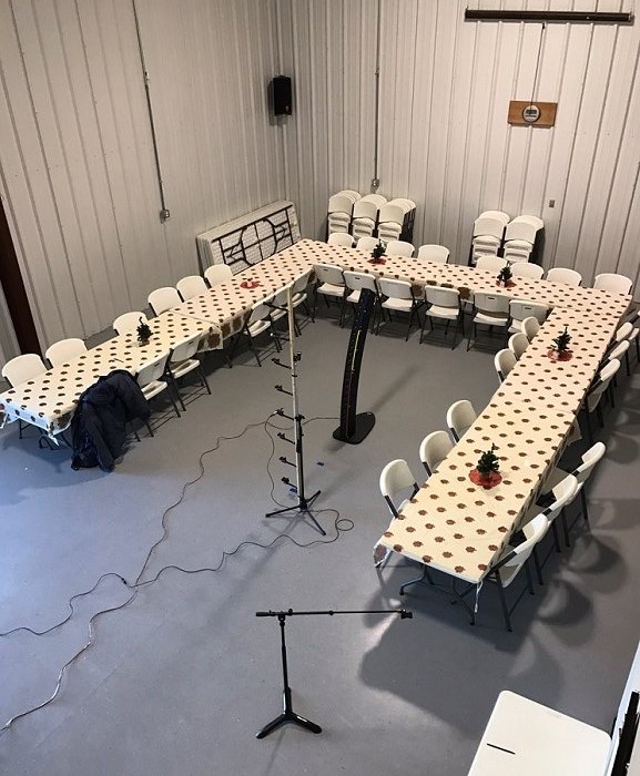
Fig. 1. Measurement location: The CBT24 array was measured in my church’s metal family center building. The room is quite large and as you can see the tables were still setup! The tiled floor provides an excellent ground-plane acoustically-reflective surface for the array to sit on.
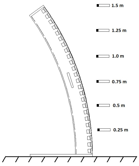
Fig. 2. Measurement mic locations: This figure illustrates the six test-mic locations that were used in the following measurements. Measurements were made at six vertical height in the range of 0.25 m (10” above the floor) up to 1.5 m (60” even with the top of the CBT24) in steps of 0.25 m (10”). Note that the test microphones were located very-close to the front of the array and are essentially even with the front bottom of the array. Very few conventional speaker systems measure well under these conditions.
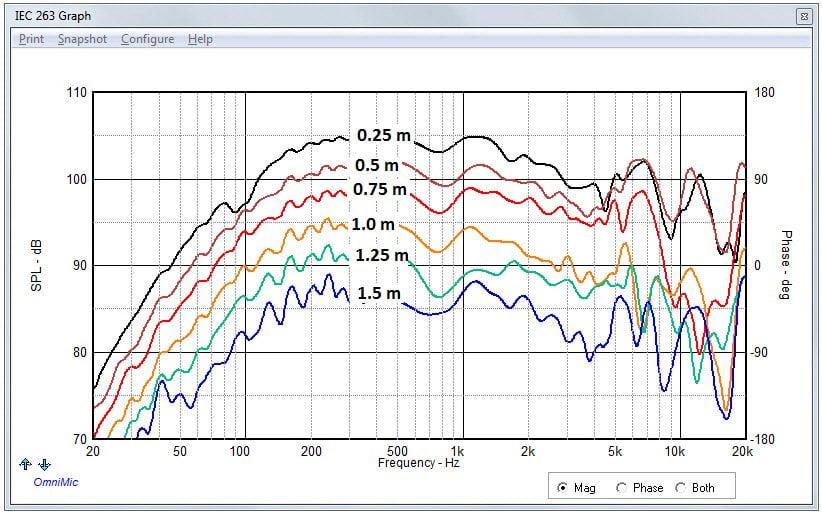
Fig. 3. Magnitude frequency response vs. height, un-normalized with miniDSP EQ: This figure illustrates the responses at each of the six test mic locations. Levels have been preserved for a 2.83 Vrms input. The level closest to the floor is highest at about 104 dB SPL, while the level drops to about 85 dB SPL at a point even with the top of the array. The responses are quite even up to about 6 kHz but get fairly erratic at higher frequencies.
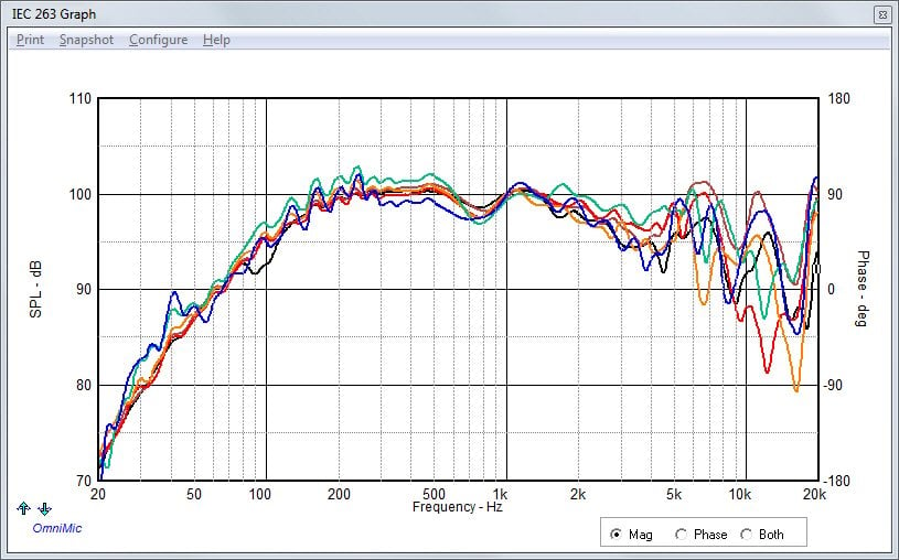
Fig. 4. Magnitude frequency response vs. height, normalized at 1 kHz with miniDSP EQ: This figure shoes the exact same curves of Fig.3 but normalized in level at 1 kHz. This graph clearly shows that the response curves are very similar to each other up to about 6 kHz and deviate at higher frequencies.
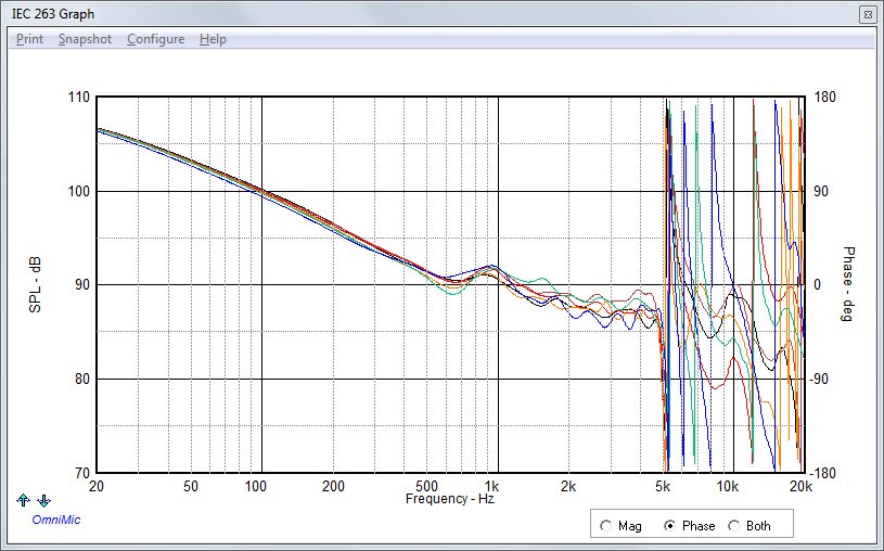
Fig. 5. Phase frequency response vs. height with miniDSP EQ: This graph illustrates the exceptional phase linearity of the CBT system at all six height locations up to 5 kHz. The rapid changes in phase at higher frequencies are due to “phase wrapping” between ±180° of the data. This shows that the system has extremely well-behaved minimum-phase behavior (just about linear phase) up to about 5 kHz at all these heights. The CBT24 will actually reproduce decent 1 kHz square waves at all these heights! See the following figure.
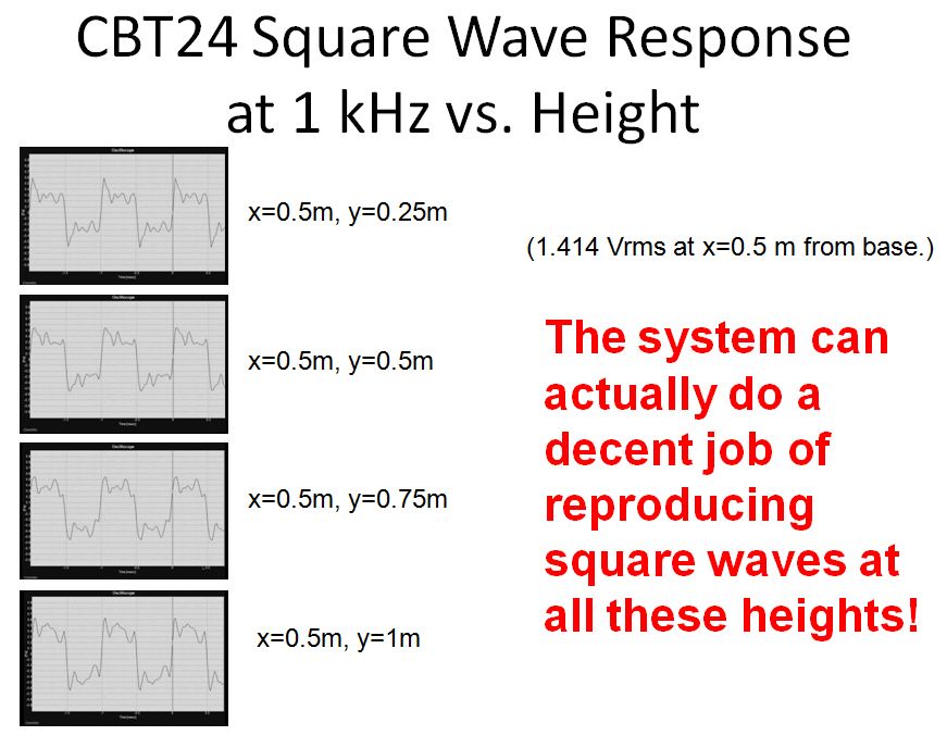
Fig. 6. Square wave response vs. height: These four OmniMic oscilloscope images illustrate the CBT24’s reproduction of a 1 kHz square wave. The test conditions for this test were slightly different than the previous three figures. The square wave responses were measured at a distance of 0.5 m from the base of the array at heights of 0.25 m, 0.5 m, 0.75 m, and 1 m. This is a rare test result for any speaker system! Usually, if a typical speaker system can reproduce square waves, it is at a magic on-axis spot where the system’s phase response is equalized to be linear. Unlike any other speaker system, the CBT24 can reproduce square waves at most points in front of the array in its coverage region.
Note: If a loudspeaker system can successfully reproduce accurate square waves, this shows that the system is essentially linear phase, time aligned, and will be able to faithfully reproduce the waveshapes of music and program material played by the loudspeaker.