
Polk Monitor 10B Crossover Upgrade: Breathing New Life into Vintage Speakers
Upgrading a Speaker Crossover: Breathing New Life into Old Speakers
Upgrading the crossover in a speaker is one of the most popular tweaks in the DIY community. Other tweaks might be easier, like swapping out feet or adding extra batting, but few others can change the sonic signature of a speaker as much as upgrading the crossover. It can be right up there with replacing the drivers, depending on how poor the stock crossover is.
From the top, I want to state that the purpose of this article is not to educate you on the design of speaker crossovers (though, we do give you a little refresher). We already have a number of articles about the design and purpose of a speaker crossover in our Speaker Design section of the website.
For more information on Crossover design:
- The
Crossover - Brain of your Loudspeaker System
- The Loudspeaker Crossover Part II: The Brains of your System
- Filter & Crossover Types for Loudspeakers
- Identifying Legitimately High Fidelity Loudspeakers: Myths & Facts about Crossovers
The goal of this article is to demonstrate that crossovers can be rebuilt and/or upgraded with superior parts and materials to enhance your listening experience. In order to demonstrate this point, I’ll guide you through the process of upgrading the crossovers in my beloved Polk Audio Monitor 10B’s.
You don't have to be a soldering expert to handle this upgrade. We’re dealing with through-hole components and large leads so the skill level isn’t very high, but you do need a lot of patience so as not to damage the printed circuit board.
Why Replace and/or Upgrade?
The audio crossover is probably the most important part of a loud speaker that you can't see; it is every bit as important to the overall speaker design as is the type of tweeter or cabinet volume. The crossover is essentially a combination of high-pass, low-pass and (sometimes) band-pass filters that separate—or steer—the various audio frequencies to the tweeter, driver, or woofer (or in Polk's case, a passive radiator).
As with any consumer product, speaker manufacturers must compete with each other for our hard-earned dollars. One way to lower the price of their product is by using “cheap” parts (especially capacitors). Large value capacitors (like the ones used in speaker crossovers) tend get very expensive (and very large) quickly. Over time, skimping here can result in the long-term degradation of resistors and capacitors. By the time these component values drift out of specification (as mine did), many people no longer even own the speakers, so the manufacturer is off the hook.
Buying audio-grade capacitors and resistors is a classic example of “you get what you pay for” (up to a point). Inductors are usually not a quality target because they're basically wire wound around an air core, unless of course the speaker employs mediocre quality iron core inductors that saturate at nominal power levels. In those cases, we look for better parts but they are usually costly and bulky in size when more than a few mH in value. In the end, you can spend more on high-end crossover components than you did on the entire speaker.
The Subject
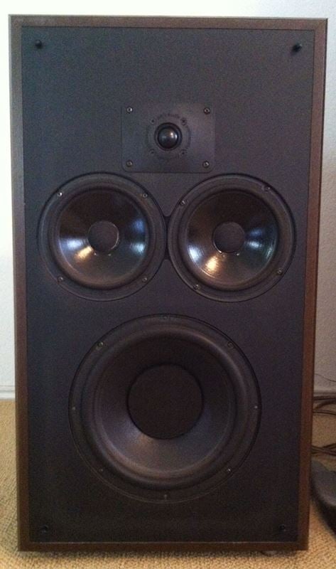
First, some background. I bought my first “real” pair of high fidelity speakers (Polk Audio Monitor 4's) fresh out of high school in 1981 with nearly all the savings from my summer job (no, my Dad was not happy); they became my college dorm/apartment speakers for 4 years. I was so blown away by them I bought a pair of Polk Audio Monitor 10B's after graduating college in 1985. I loved them so much that I needed another set, so I traded a friend an old stereo amplifier for his pair of 10B's in 1989 (yes, he's still my friend)! At that point, all the pieces were in place for what has become my 5.1 speaker set-up today.
After years of reading the Polk Audio (Vintage) Speaker forum, I finally decided to take the plunge and rebuild/upgrade the crossovers in my Monitor 10B's based on the schematic published by Polk (Figure 1) and component manufacturer recommendations tried and tested by forum members.
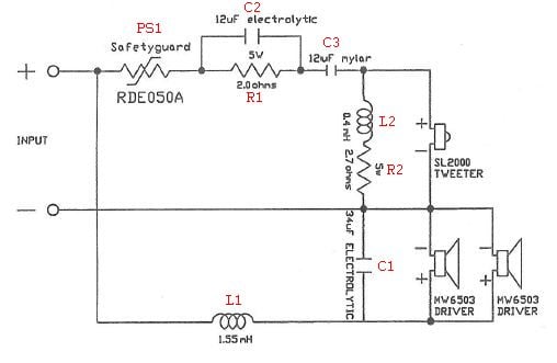
Figure 1 – Crossover Schematic
The Monitor 10B crossover:
-
passive (there are no “active” transistors or integrated circuits)
-
two-way (there is no band-pass filter)
-
second-order (which results in the tweeter and driver(s) being connected “out of phase” to account for the 180 degree phase shift of the second-order filter)
It only uses resistors, capacitors, inductors and a (re-settable) fuse to perform its function. What looks easy to design is anything but, and the fact that Polk makes the schematics for its vintage speaker designs readily available is a testament to the greatness of this American company. I spent about $100 per speaker on parts for this project, taking a middle-of-the road approach, with SoniCaps and Mills resistors from Sonic Craft. These components have garnered a lot of favorable recommendations on the Polk Audio forums, and yield considerably better performance than Radio Shack quality components without the extreme price of Clarity capacitors or Duelund resistors. In the analog world (speakers are not a digital medium), it's not just about specifications—although component value drift does alter crossover frequencies—but also about the purity and warmth (or lack thereof) of the sound. It truly can be a “black art”.
Materials Needed:
- 40 Watt (minimum) soldering iron
- solder and solder wick (for removing the old parts)
- wire-cutters and/or strippers (often the same tool)
- solid 22 gauge (or thereabouts) wire
- needle-nose pliers (the smaller the better)
- resistors and capacitors (depends on what you choose to go with)
The Upgrade Process
The first step in any crossover rebuild is locating and removing the crossover board; in my case it is attached to the back side of an assembly around which is wound the large (L1) inductor and upon which is mounted the speaker terminals (Figure 2). Notice the board is secured with two small screws; there are also six wires (four visible that connect to the tweeter and drivers as well as two hidden that connect to the positive and negative speaker terminals) that must be desoldered to completely remove the board for component removal/replacement.
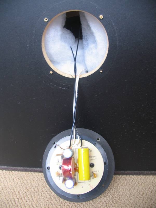
Fig2 - Original Crossover
Figure 3 is a top-down view of the board after everything but the small (L2) inductor has been removed and Figure 4 is the back of the same board. If you look closely, you can correlate the silk screened component labels with the values on the schematic. Now the fun begins!
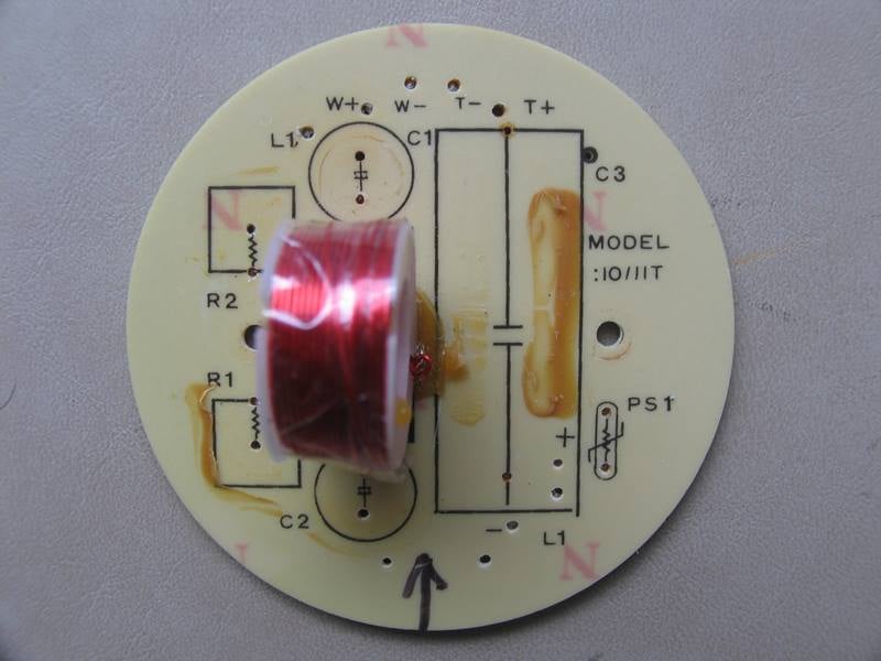
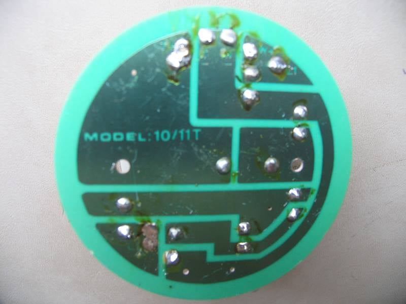
Figure 3 Figure 4
A quick peek at Figure 6 will tell you the new capacitors are physically much larger than the ones they replace. This made for some interesting mechanical problems that required some creativity to solve. Remember, everything has to fit back through the same opening that it was removed from. While the finished product is limited to the diameter of the board in the “X-Y” axes, there is some flexibility in the “Z” axis; specifically, I could stack/extend components above the board to the depth of the speaker cabinet (it just so happens the mount sits between the two drivers). That's exactly what I did after splicing the blue and white striped wire to one end of C1 (see the red heat shrink) since I could only insert one lead from that capacitor into the board. This is more clearly shown in Figure 5 along with how I elevated the resistors to allow for increased air flow (they are the only things that really get hot in a crossover). In addition, if you closely compare Figures 3 and 5, you'll notice I had to rotate C2 after lead insertion (taking care not to short the leads together) as there was no way it could extend into L2.
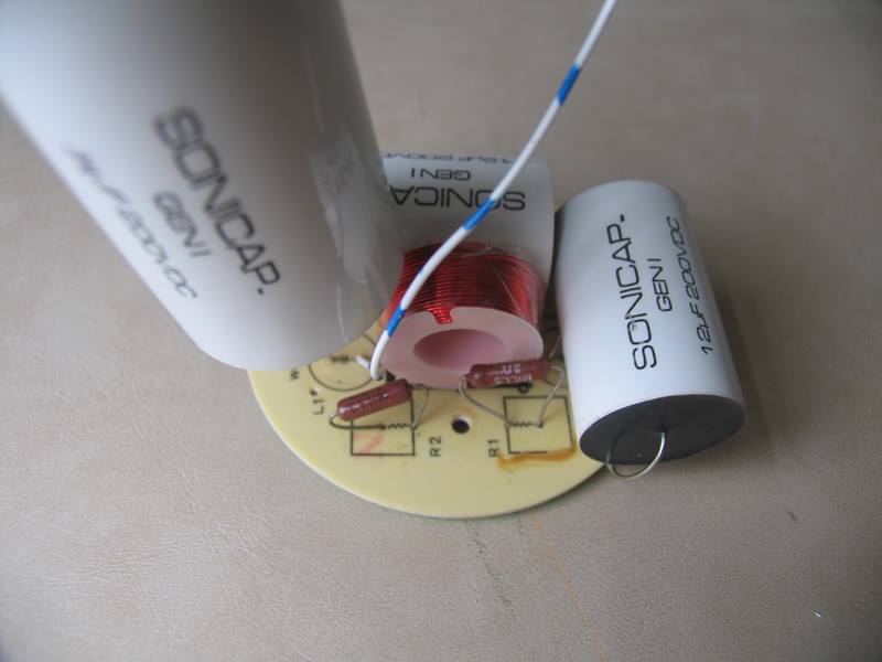
Figure 5 - Upgraded Crossover
Here's a tip: don't trim component leads on the back side of the board until you've completed the soldering process; that leaves you the option of raising, lowering, or rotating a part if necessary. Examining Figures 2 and 6, you'll notice I had to label the tweeter and driver leads (before desoldering) since there was no easy way to distinguish between them. Last but not least, I should point out that I replaced poly-switch PS1 (essentially a re-settable fuse) with a 0.5 Ohm resistor. Why? Because these parts are notorious for “false opens” and I maintain good amplification with no clipping.
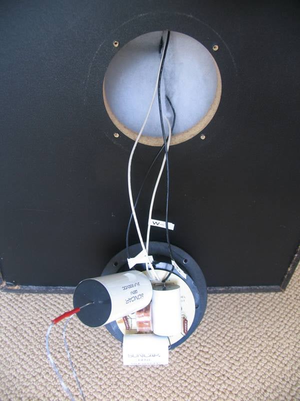
Figure 6 - Installing New Crossover
Summary
It's common opinion that crossover upgrades require a break-in period on the order of 100's of hours. It's not that they won't function; it's just that they won't allegedly perform optimally until the break-in period is complete. We have mixed opinions about speaker break in as you can see in our article: Speaker Break in: Fact or Fiction, but I keep an open mind and enjoyed the whole experience of rediscovering the upgraded speakers with all of the science and conjecture aside.
Sample measurements of the components removed yielded some interesting results:
- 12 micro-Farads (treble leg) capacitor measured 13.7 micro-Farads
- 34 micro-Farads (bass leg) capacitor measured 36.8 micro-Farads
-
poly-switches measured 1.3 and 1.7 Ohms
Not only was one capacitor outside its clearly marked +/- 10% tolerance, but the other had changed enough to materially affect crossover frequencies. It's also worth noting that all of the replacement components are manufactured to +/- 5% tolerances, so even if they do eventually drift in value, the delta will still be less than the components they replaced. In addition, both poly-switches measured considerably beyond the 0.5 Ohm resistor I replaced them with, resulting in a dampening effect on the upper (tweeter) frequency spectrum that I am now more than happy to be rid of.
Personally, I noticed an immediate improvement in clarity and “tightness” of the mid-to-low range. I was also pleasantly surprised to hear a more consistent (over volume range) tweeter output, probably due to the fact I didn't have a poly-switch varying its resistance in response to the applied power. The best news is that things will only get better over time! I noticed some “settling” in the 30 hour range as well as the 100 hour range. I've also heard that imaging—the holy grail of speaker design—will continue to improve through the 500 hour mark.
While there are other types of speaker modifications/upgrades, from simply replacing tweeters (which I have also done) to replacing/resealing baffles, crossover upgrades can make an “in your face” difference merely due to common component degradation over time. Obviously, I'm looking forward to many hours of listening enjoyment from my “new” vintage speakers!
Stanton was born and raised in Kansas City, where he was exposed to the rich culture of jazz at a very young age. He's a drummer and an electrical engineer and loves to review jazz music for us.
View full profile