
Component Video Cables - The Definitive Guide
Component video cables are a key interconnect element to any Home Theater System. To better understand how these 75-ohm cables can affect a video signal from a DVD player, it is helpful to cover some fundamental engineering principles that define them. To begin with, the primary purpose for 75-ohm component video cables is to conduct an AC video signal from a source (DVD player) to a load (TV monitor) with as little change to that signal as possible. There are numerous electronic textbooks and Internet sites referenced at the end of this article that discuss cables and wires in terms of equations and engineering principles. When applying textbook equations and engineering principles to component video cables it becomes clear that a well engineered and manufactured cable will help keep the source signal within the cable conductor to minimize loss, while keeping out noise from other outside sources.
1.0 Engineering 75-ohm Interconnects
Unlike audio cables, which only conduct low frequency data on the order of 20Hz to 20,000Hz, video cable must transmit higher frequencies up to levels of around 8MHz to 10MHz for NTSC and for over 35MHz for HDTV. At these frequencies, there are a number of factors that can create interference, signal loss, and signal degradation, all of which can be identified and minimized by applying fundamental electrical engineering principles. This article is intended to discuss these basic engineering principles, provide information on various manufacturing techniques of component video cables and coaxial cables, and explain the different types of component video cables on the market. There are a number of concepts and misconceptions about component video cables that will be addressed in this article, many of which will be proved or disproved mathematically. As you read this article, it is not necessary to focus on the calculations as much as the conclusions that are drawn by them.
1.1 Impedance Defined
Impedance is a measure of the ability of an AC network to impede the flow of charge or current through a network. For our application, the network is the combination of the source (DVD player), load (TV monitor) and component video cables. There are many derivative equations that apply to impedance calculations, however at the higher frequencies of video signals, typical cable laws are not entirely applicable. At frequencies relative to component video (10MHz maximum), impedance is more closely related to specific resistance for electro-magnetic waves. It can actually be defined as the load a cable poses at high frequencies.
For sinusoidal AC signals of video frequencies flowing in one end of the cable, the signals travel as an electrical wave at the same potential energy down the cable. If the cable length is an extremely large number of wavelengths at the frequencies of that AC signal, the ratio of the AC voltage to AC current in that traveling wave is defined as the characteristic impedance of the cable as defined by the following equation.
wavelength (in meters) = v / f
where f is the frequency of the signal in Hz, v is the velocity of the signal = 3x10^8 meter/second
For example, at 60-Hz the wavelength is 3100 miles; at 10-MHz it is 30 meters (max frequency for component video).
1.2 75-Ohm Impedance of Component Video Cables
Component video cables are composed of coaxial cables. As discussed in the section above, since most component video cable lengths are shorter than 30 meters, they are considered short compared to the wavelength (10-MHz max for component video) of the signal therefore, coupling between circuits can be represented by lumped capacitance and inductance between conductors. With this in mind an electrically short coaxial cable ( < 1/10 wavelength) can be analyzed by using principles outlined in basic network theory.
As indicated in Section 1.1, the characteristic impedance of the coaxial cable is primarily determined by the size and of the conductor and the type and size of dielectric.
The following formula can be used for calculating the characteristic impedance of coaxial cable: (formula taken from Reference Data for Radio Engineers book published by Howard W. Sams & Co. 1975, page 24-21).
| Characteristic Impedance (Zo ): |  |
Where:
d = outer diameter of inner (center) conductor (approximate value for stranded)
D = outer diameter of dielectric
ε = dielectric constant (ε=1 for air)
This equation supports the fact that the characteristic impedance of a coax cable is directly related to the diameter of the conductor and the dielectric. For component video cables, this characteristic impedance should be 75-ohms. With characteristic impedance (Zo) held at a constant 75-ohms, the variables are the diameters and dielectric constant.
Once an understanding of the engineering principles behind 75-ohm cables is established, practical issues that apply to designing, or considering the purchase of a 75-ohm video cables include conductor material and diameter, dielectric material and diameter, grounding shield, noise protection, termination (solder joints) and RCA connector design. Each of these topics will be discussed within the sub-Sections of 3.0.
Check out our Transmission Line Effects of Component Video Cables Supplemental for a more detailed look into this topic.
2.0 Signal Loss
Prior to reviewing basic 75-ohm cable design principles, it is helpful to understand what causes signal loss. Signal loss or degradation, can occur from a number of factors which include internal impedance, Electro Magnetic Interference (EMI) including EMI in the Radio Frequency range (RF noise), mismatched impedance, flawed basic cable designs or inconsistent/bad manufacturing. Terms that are often misleading and thought to cause signal loss are skin effect and strand jumping. As you will see in Section 2.3, skin effects are minimal and not significant at the frequencies related to video cables. Strand jumping is a term a few manufacturers use for audio cables due to "skin effects," but since skin effect is related to frequency, the same myth can be applied to the higher frequencies of video. Section 3.1.1 will discuss these issues in more detail.
2.1 Internal Impedance of 75-ohms
A properly designed and manufactured component video cable should have an internal impedance of 75-ohms, which is design impedance for most video components, especially in Home Theater.
However, because of form factor limitations of the RCA connector, it is nearly impossible to design a true 75-ohm connector. Since the connector contact area is very small, relative to wavelength, maintaining a true 75 ohm termination is not that critical, however it is good engineering practice for the manufacturer to attempt to come as close as possible to nullify any unwarranted losses due to impedance mismatches or inconsistant manufacturing techniques.
One method of considering impedance is being comprised of reactive and resistance values and therefore related to resistance and capacitance. In a standard audio cable for example, the internal impedances are between 35-ohms and 50-ohms. Since they are designed to carry low frequencies (20Hz to 20kHz), resulting in much longer wavelengths than the length of the cables themselves, audio cables by their design, aren't concerned with characteristic impedance as much as lumped R,L,C parameters. However, if audio cables are used in place of component video cables, or poorly constructed component video cables are used that are not a true 75-ohm characteristic impedance, the lower impedance value of these cables may result in a partial signal reflection do to a mismatch in impedance, depending on the length of the cable. Detailed information on mismatched impedance and internal impedance are provided within the sections 2.2 and 3.0.
Component Video Cables - The Definitive Guide - page 2
2.2 Electromagnetic Interference (EMI)
Electromagnetic Interference (EMI) is around us at all times. It comes from radio towers, sun spots, cell phones, modems, remote controls, computers and a number of other signals that are generated from most electronics used in every day life. EMI transmissions exist in wide ranges of frequencies including Radio Frequency range (RF noise). EMI exists within the range of video signal frequencies and at frequencies that are harmonically related to video signals. It is possible for stray signals from EMI to find their way into a video cable and therefore, create a false signal or internal noise within the component video cable. The result can range from very minor to significant depending on the noise origination and strength. A quality 75-ohm shielded video cable implements several methods to minimize EMI from entering into the cable. These methods include the use of braided grounding shields and nonmagnetic foils as explained in the sub-Sections of 3.0.
2.3 Mismatched Impedance
Mismatched impedance is one of the most common and most frequently experienced sources of signal degradation. This phenomenon occurs when a high frequency bandwidth signal, designed to be matched to a characteristic impedance of 75-ohms, encounters different impedances through its signal path (IE. Transmission Line), usually on the order of 35-ohm or 50-ohm for Home Theater applications. It can occur in long runs of video cables ( > 1/10th the wavelength) that do not use true 75-ohm cables, or it can occur from the DVD player or the TV monitor, depending on the nature of their internal impedances. This mismatch can create a bounce back effect or reflection that results in a delay and/or loss of signal level for certain frequencies. Thus for component video cable, transmission line effects of any cable lengths beyond 3 meters (remember 1/10 of 30 meters) must be considered.
When the characteristic impedance changes in a cable, part of the signal (incident wave) is reflected. The reflection coefficient can be calculated as:
Where Vi and Zo are the incident voltage and characteristic impedance of the first media. Vr and Zr represent the reflected voltage and characteristic impedance of the media that caused the reflection.
An open circuit implies that Zr = ∞ or ρ = 1, and a short circuit implies that Z R = 0 or ρ = -1. A perfect reflection coefficient is when Zr = Zo or ρ = 0.
The decibel loss due to reflection is given by:

Power from reflected signals are reflected back to the source (DVD player) so that phase addition and subtraction of the incident and reflected waves create a voltage standing wave pattern on the cable. The ratio of the maximum to minimum voltage is know as Voltage Standing Wave Ratio (VSWR) and can be defined as:
VSWR = Emax/Emin = (Ei+Er)/(Ei-Er)
where:
E max = maximum voltage on the standing wave
E min = minimum voltage on the standing wave
E i = incident voltage wave amplitude
E r = reflected voltage wave amplitude
In the case where the conductor line is properly terminated into its characteristic impedance (75-ohm for component video cables), VSWR = 1 and there is no reflected wave.
The reflection coefficient (r) is defined as E r /E i and in general, it will be a complex number.
| Additionally we define: | r = (Zi - Zo) / (Zi + Zo) |
The refection coefficient (r) , is the absolute value of the magnitude of G .
If the equation for VSWR is solved for the reflection coefficient, it is found that:
| Reflection Coefficient = ρ = |r| = (VSWR -1) / (VSWR + 1) |
Consequently,
VSWR = (1 + p) / (1-p)
The return loss is related through the following equations:
Return Loss = 10 log [Pi/Pr] = -20 log [ (VSWR -1) / (VSWR + 1) ] = -20 log ρ
Return loss is a measure in db of the ratio of power in the incident wave to that in the reflected wave, and as defined above, always has a positive value. For example if a load has a return loss of 10 db, then 1/10 of the incident power is reflected. The higher the return loss, the less power is actually lost.
Impedance mismatch can occur when a cable with internal impedance less than 75-ohm is connected to a true 75-ohm load, such as a video line driver in a Projector to DVD player. In this situation, some of the frequencies that make up the signal will be reflected back to the source. Since the source is a 75-ohm impedance, this reflected signal is sent directly back to it creating a delay effect at certain frequencies. This delay, for example, can show up as a ghost in the picture. Multiple ghosts resulting from multiple frequency reflections can look like ringing around the original image. These reflections can also cause partial signal cancellations at various frequencies corresponding to a partial signal loss resulting in a loss of picture detail or color.
Other examples of mismatched impedance include any mismatches between the source's output impedance (DVD player), the cable's characteristic impedance (using audio cables or a poorly made 75-ohm cable), and the load's input impedance (the TV monitor). One possible scenario is if damage to a component video cable from crushing or kinking has occurred, or if the connectors are improperly installed, the internal impedance of the cable is changed resulting in reflection and power or signal loss.
2.4 Skin Effect
Skin effect is sound engineering phenomenon that can be defined mathematically, however as outlined in the following examples, it is not detrimental to low frequencies within the range of audio and video cables. Skin Effect is dependent on a number of factors including conductor diameter, the permeability / conductivity of the cable, and the frequency of the transmitted signal.
For the purposes of understanding skin effect, the following discussion presents a general outline and example. To begin with, an electromagnetic wave traveling in a coaxial cable produces both, an electric and a magnetic field between the inner conductor and the outer return (ground). The electric field (E) is radial and varies in time. As an alternating current flows along the inner conductor, an oscillating magnetic field (H) circles that conductor.
Electric field (E) and magnetic field (H) belong to the principal mode in a coaxial line.
At high frequencies, resistance increases on a conductor due to skin effect. The strength of a magnetic field (H) at these higher frequencies is enough to cause the alternating current on a conductor to spread unevenly throughout the conductor. Instead, it is strongest at the outer surface and decays exponentially at points further into the conductor. The field is opposite for the ground as the force from the magnetic field causes the current inward. This phenomenon is called the skin effect. Skin effect causes 95% of the current to be carried within about three skin depths of the surface of the conductor. As a result, the current only flows on the outer surface of the inner conductor and the inner surface of the outer return. The material beyond several skin depths has little effect on the wave therefore the signal is transmitted down a decreased area of conductor. The decreased area carrying the signal results in an increase in resistance within the cable resulting in a potential for loss of signal. For audio and video frequencies, this change in area and increase in resistance is not significant enough to create a measurable loss in signal. This can be verified through basic, fundamental engineering calculations as shown in the following example. In fact, if you continue with these calculations you will find that it doesnât even become an issue until over 1GHz which is significantly higher then audio, component video and HDTV signals.
As explained above, the current density varies exponentially inward from the surface of the conductor by 1 / e (current density ratio = J), where e ℮ = 2.718. The distance in which the current density decreases to 1 / e ℮ of its surface value is called the Înominal dept of penetration.â
The current density ration listed above J = 1/ e ℮ = 1 / 2.718 = .368 amperes / meter
For reference purposes, the formula for approximating the actual skin depth is:
√ Square root of 2 / (2 x л x ° x permeability of the cable x conductivity of the cable)
This equation can be simplified for a copper conductor coaxial cable found in most component video cables, by applying the applicable constants. When simplified, the formula for calculating the nominal depth of penetration is:
- Nominal depth of penetration for copper = δ = 6.64 / square root of √ f
- Depth of penetration at 60 Hz, δ = .857cm;
- Depth of penetration at 10 KHz, δ=.066cm;
- Depth of penetration at 10 MHz, δ=.0021cm = 21 microns
As discussed above, 95% of the current is carried within about three skin depths of the surface of the conductor. At 10MHz the current density for one skin depth (.857cm) is defined as J = .368 or 36.8% of the surface value. This means that 63.2% (100% ö 36.8%) of the signal is at one skin depth. At two skin depths the current density is 1/℮ e^ 2 = .135 or 13.5% of its surface value. This means that 86.5% (100% - 13.5%) of the signal within two skin depths. At three skin depths the current density is 1/℮ e^ 3 = .05 or 5% of the surface value. This confirms that 95% (100% - 5%) of the signal is within three skin depths.
Once the depth of penetration is determined, the area of the conductor can be found and used for calculating the resistance in the cable. As discussed, the increased resistance due to decreased area will result in a signal loss.
For solid, round copper conductors the AC and DC resistances are approximately related by the following expression (ITT 1968):
RAC = (0.096*d* f ^1/2 + 0.26) x RDC
where d is the conductor diameter in inches and f is the frequency in Hz (hertz).
For d* f ^1/2 > 10, this equation is accurate within a few percent. For d* f ^1/2 < 10, the actual AC resistance is greater than given by this equation. If the material is something other than copper, the first term in this equation must be multiplied by a factor of (µr / ρ r)^1/2 where µr is the permeability of the conductor material and ρ r is the relative resistivity of the material compared to copper.
AC resistance for conductor:
d = (perimeter of cross section) / pi
Quick Facts on Skin Effect
- Hollow Tube and Solid Core with same diameter and same material have same resistance
- Depth of Skin Layer decreases by a factor of 10x for every 100x increase in frequency.
- RF resistance is often much higher than DC resistance.
- Rough estimate of fc (cutoff frequency) where nonferrous wire show skin effect:
- Frequency (MHz) = 124 / (d^2 ), where d is diameter in mils.
- Above cutoff frequency, resistance increases by 10x for every 2 decades of frequency. Roughly 3.2 for every decade.
The following example determines the power loss due to skin effect on a typical 6-foot (2-meter) 18-AWG cable with a 10MHz signal (max range of component video).
First, it is important to calculate the power loss of a 6 feet length 18-AWG solid copper conductor (0.04ä = 40.2-mils diameter) @ 10MHz with a DC resistance of 6.386-ohm / 1000ft (Table data on copper wire).
DC resistance = (6 ft)*(6.386-ohm / 1000ft) = 38-mohm.
The equation where Skin Effect starts is defined as:
fc = 124 / (d^2 )
For our example:
fc = 124 / ((40.2-mils)^2) / (1000^2 ) = 75-kHz
10MHz is approximately x decades above 75-kHz; solve for x by:
Frequency Ratio = fx / fc= 10*10^6 / 75*10^3 = 133.3333
Therefore, 10MHz is 2.12 decades (log 133.333) above 75kHz
Zloss = (38-mohm)*(10)*(2.12) = 0.81-ohm Resistance
The following ratio can be obtained with this equation:
Zratio = Zo/ (Zo + Zloss) where Zo is 75-ohm (defined by cable)
Zratio = .989
To calculate the decibels of power loss use the following equation.
10 x Log (Zratio ) = 10 x Log (.989) = -0.047 db
In a solid conductor of 18-AWG with a 10MHz signal, there is only 0.047 db power loss of signal due to the DCR of the cable and the AC resistance resulting from skin effect.
For more information on Skin Effect and its insignificant effects on audio cables, check out the following article: Skin Effect Relevance For Speaker Cables.
Component Video Cables - The Definitive Guide - page 3
2.4 Flawed Cable Designs or Manufacturing Techniques
There is no substitute for good engineering. But even beyond good engineering, there has to be quality manufacturing to assure that all the engineering principles were correctly implemented. There are numerous 75-ohm video cables on the market and at times, it is challenging to determine which include good engineering/manufacturing, and which are only comprised of 'good' marketing.
Pursuing the Truth: The audio and video cable market is filled with a number of scams and fallacies that create confusion among consumers (us). Some ideas to consider when shopping for a 75-ohm cable are as follows:
-
Good Engineering: Try to recognize a design feature that makes sense for its purpose over ones that seem too good to be true and may actually be a marketing scam. For example, there is a new component video cable hitting the market that doesn't use conventional RCA connectors. It actually has a "Bullet Connector" derived for audio cables. Based on the RCA connectors geometry and the governing equations discussed in this article, its design cannot produce near a 75-Ohm termination and is no better than a standard audio rca termination. Since the manufacturer choose to use this type of termination, one must wonder if they choose the correct dielectric and spacing requirements to maintain a cable chacteristic impedance of 75 ohms. If not, this may cause impedance mismatching for cable lengths 3 meters or greater resulting in the reflections and signals loss addressed in Section 2.2.
-
The package alone does not define the cable: Some cable Manufacturers like to package their product in fancy, designer packages. Just remember that the package ends up in the trash and the signal the cable transmits is what you will be living with. The primary purpose of the package is to protect the cable from damage during shipping and receiving from the manufacturer to the end user. It should prevent kinks and bends in a cable which can result in diameter changes that affect the impedance.
-
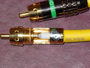
Bad, inconsistent manufacturing: There are a number of small cable manufacturers to be found on the Internet. Nothing is wrong with a small manufacturer as many of the larger companies once started small. However, it is important that these small manufacturers produce a consistent product. Most cable manufacturers (large and small) hand-solder the RCA connectors onto the cables. This is a valid procedure provided it is done by experienced staff and the solder joints are carefully inspected upon completion. Problems that can occur during soldering are melting of the dielectric, excessive solder, incomplete solder joints and so on. As an example of how soldering can damage a cable, it is worth considering the dielectric. If the low melting point dielectric material is overheated during the soldering process, it can easily melt resulting in a change in diameter. Based on the governing equation for internal impedance, by changing the diameter of the dielectric the impedance of the cable has effectively been changed. Some Manufacturers may have a great design, but if they are inconsistent with their soldering or manufacturing techniques, the cables will also be inconsistent. This can mean that from batch to batch, or from cable to cable, the customer is not guaranteed they are purchasing a quality cable. The following pictures show two forms of solder joints on actual 75-ohm component video cables. These cables were taken right out of their package and the RCA barrels were removed to expose the solder joints. Note the lack of quality in the one on the right defined by the inconsistencies in the solder joint.

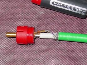
Both cables were hand soldered during manufacturing, yet it is clear that the cable on the left did not alter the diameter of the white colored dielectric while the cable on the right did. Also, look at the quality of the solder joint in the left side cable. There are no solder bulges, dielectric melting, or exposed wires. The result is the creation of as near perfect a 75-ohm termination as possible. The cable on the right is another story. It seems that little care was taken to protect the dielectric as seen by the noticeable melting near the end of the green jacket layer. Also, there are exposed conductor wires, no termination protection and the solder joint displays extremely poor quality. With inconsistencies and the multiple diameter changes of the conductor/dielectric on the right, it is obvious this manufacturer created a poor termination and this cable will likely have significant signal loss at certain video frequencies.
Pursuing the Truth: Don't be afraid to remove the RCA barrel and inspect these solder joints for yourself. The connector barrel usually unscrews and can be slid down the cable without damage. Some manufacturers hard mount the RCA barrels by placing shrink sleeve over them or implementing other methods so they cannot be removed. These manufacturers may be so bold as to express elaborate reasons for doing this, but the bottom line is that if you cannot inspect their solder joints, you should use caution when selecting their cables.
3.0 PRACTICAL APPLIED CABLE LOGIC
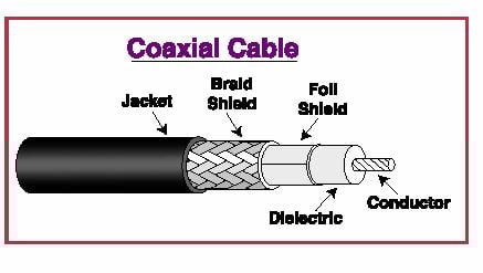
A basic component video cable is an assembly that consists of a coaxial cable and RCA connectors that have been soldered together at the termination. The coaxial cable is also an assembly of its own. At a minimum, this assembly includes a conductor, ground, dielectric and jacket. Coaxial cables with improved quality also contain a foil shield, friction reducer (not shown in diagram and not used in all coaxial cable) and at least one braided shield (to serve as a ground and shield from EMI. Each part of these subassemblies, play an important role in the quality of the component video cable and is governed by basic engineering principles, as discussed below.
Pursuing the Truth: Most, if not all, component video cable Manufacturers, purchase, not make, their coaxial cable. The component video cable Manufacturers specify the type/quality of coaxial cable they purchase (and there are many) match it up with a specified RCA connector (another purchased item) and solder them together. After the assembly is made, they neatly package the end product and market it to the Home Theater World.
3.1 Conductor and Ground
The inner core of coaxial cable is called the conductor. For component video cables, the conductor is usually made with stranded wire for improved flexibility and increased surface area, but solid conductor works just as well although it is a bit stiffer. The conductor wire is comprised of either Silver Plated, Oxygen Free High-Conductivity (OFHC) Copper, pure OFHC Copper, or pure Silver, depending on what the component video cable Manufacturer specified and purchased. The use of different materials for the primary conductor becomes apparent with video cables above 30 meters, as signal losses increases due to conductor resistance. However, the first order effects that attribute to signal loss of runs this long at the bandwidth of these video frequencies is transmission line effects resulting in impedance mismatching if the characteristic impedance of the cable is not 75 ohms.
It is important to clarify the reason why OFHC copper is used in place of pure, unalloyed copper. Unalloyed copper is an important metal for cables because of its high electrical conductivity. Electrolytic tough-pitch (ETP) copper is an inexpensive industrial copper used for the producing wire, rods and strips. ETP copper has a nominal oxygen content of about 0.04%. Oxygen is almost insoluble in ETP copper and forms interdendritic Cu20 when the copper is cast. For most applications the oxygen in ETP copper is an insignificant impurity. However, when ETP copper is heated to a temperature above around 400C / 752F (such as when using a high temperature solder) in an atmosphere containing hydrogen (found in air), the hydrogen can diffuse into the copper and react with the internally dispersed Cu20 to form steam according to the chemical reaction:
Cu20 + H2 (dissolved in Cu) --- 2Cu + H20 (steam)
The large water molecules formed by the reaction do not diffuse readily and therefore form internal holes, particularly at the grain boundaries, which makes the copper brittle. Brittle copper at solder joints (the area that has been heated) will decrease the life of the cable since this area is usually under high stress from supporting the weight of the cable at the connector point. To avoid hydrogen embrittlement caused by Cu20, the oxygen can be reacted with phosphorus to form phosphorus pentoxide (P205), but this is not practical when hand soldering RCA connectors onto a coaxial cable. Another way to avoid hydrogen embrittlement is to eliminate the oxygen from the copper by casting the ETP copper under a controlled non-oxygen reducing atmosphere. The copper produced by this method is called oxygen-free high-conductivity (OFHC) copper and is alloy C10200. OFHC can be heated and soldered in an open environment without becoming brittle at the heat effect zone (solder joint).
Pursuing the Truth: The fact of the matter is that OFHC copper and pure unalloyed copper, both oxidize at around the same rates. Some cable manufacturers use the OFHC as an advertisement that it will not oxidize, or it will oxidize less than other copper conductor materials, but there is no truth to these claims.
There are valid methods that help minimize, but never totally prevent oxidation. Silver plating is the most common, but it cannot totally prevent oxidation. Silver does indeed oxidize, but at a much lesser rate than copper. It is cost prohibitive to use in pure form for component video cables, especially if it is over 2-meters. By adding a silver-plating over copper, it forms a layer of protection on the copper minimizing its direct exposure to air, thus resulting in a reduced rate of oxidation at an economical price.
3.1.1 Conductor
There are many types of conductors used in coaxial cables including various forms of stranded wire and solid wire. Component video cables tend to be made from stranded conductors for additional flexibility, but both solid and stranded wires produce quality conductors. There are many methods and procedures to manufacture a stranded conductor.
Pursuing the Truth: Be forewarned that some cable manufacturers use nonstandard conductors along with a caveat that it prevents 'Strand Jumping.' Through clever marketing schemes and tactics, this made up term is promoted as if stranded wire has a problem that creates a loss of signal, especially in audio frequencies, due to electrons jumping between strands. By using this made up term, they attempt to justify the use of 'proprietary' cables for their audio and component video cable assemblies to justify a higher price. Be fully assured that 'Strand Jumping' is not a real engineering principle used to define any level of performance, induced distortion, or loss for coaxial, or any types of cables. In fact, this made up term is not found in any engineering or physics textbooks related to AC signals, cables and so forth. You will also not find any technical papers in AES, IEEE or any other Engineering Organization that speaks any relevance about this fallacy as the perpetuators of this fallacy fear peer review from real engineers and scientists. When you see this term, ask the manufacturer or AV Forum host to quantify the loss with a measurement or calculation and see what creative (mostly philosophical), but nonrealistic and fictitious answer they provide. The bottom line is at the frequencies we are dealing with, there are no multipathic effects within the cable. Even if there were, the results cannot cause diode rectification as some vendors claim.
The truth of the matter is that current flows through the path of least resistance. Resistance through the strand of reasonably short cables is significantly less than resistance between air gaps or metal oxide layers found between two strands therefore, the signal will not jump. Secondly, each strand within the bundle is at relatively the same electrical potential and thus the signal has no reason to jump. If there is any logic to strand jumping (which there isn't) it is like saying that if you change lanes on I4, you will not end up in Tampa.
There are really no significant advantages or disadvantages between the use of solid and stranded wires for a cable conductor outside of flexibility and a slight increase in surface area. For the purpose of understanding stranded wires, it is helpful to review the assortment of types they come in. Some of the more common methods for stranding the conductor include Bunch, True Concentric, Equilaly, Unidirectional Concentric, Unilay and Rope.
![]() Bunch - Strands of any number are twisted together or "bunched" with the same lay direction but without a defined geometric configuration. The "bunched" construction will have a variable cross-section and does not allow a well-extruded product to be produced because of its fluctuating construction and diameter.
Bunch - Strands of any number are twisted together or "bunched" with the same lay direction but without a defined geometric configuration. The "bunched" construction will have a variable cross-section and does not allow a well-extruded product to be produced because of its fluctuating construction and diameter.
Smooth bunch constructions, in recent years, have solved the major problems by arranging the strands in geometric configurations and by providing a consistent diameter.
True bunching is the lowest cost method of stranding with smooth bunch being slightly more expensive.
True Concentric - A central strand surrounded by well-defined layers of helically laid strands. Each layer has reversed lay direction and an increasing lay length in each succeeding layer.
Equilay - A central strand surrounded by well-defined layers of helically laid strands. Each layer has reversed lay direction but the lay length is the same in each layer.
![]() Unidirectional Concentric - A central strand surrounded by one or more layers of helically laid strands with the same direction of lay and increasing lay length in each succeeding layer.
Unidirectional Concentric - A central strand surrounded by one or more layers of helically laid strands with the same direction of lay and increasing lay length in each succeeding layer.
![]() Unilay - A central strand surrounded by one or more layers of helically laid strands with the same lay direction and the same lay length in each succeeding layer.
Unilay - A central strand surrounded by one or more layers of helically laid strands with the same lay direction and the same lay length in each succeeding layer.
![]() Rope - Cable stranded groups of any of the before mentioned into a very large cable. Rope construction is used to create a flexible conductor, typically 8 AWG and heavier, but in some cases is used to create very flexible fine wire constructions.
Rope - Cable stranded groups of any of the before mentioned into a very large cable. Rope construction is used to create a flexible conductor, typically 8 AWG and heavier, but in some cases is used to create very flexible fine wire constructions.
As indicated in Section 1.2, a 75-ohm cable is dependent on the ratio of the diameter of the wire bundle (for stranded conductors) and the diameter of the dielectric (d/D). Therefore, there are many possible diameter combinations that will produce a 75-ohm cable. Wire bundle diameters are measured as American Wire Gauge (AWG). Although the diameter ratio needs to remain constant for a 75-ohm cable, as shown in Section 1.2, the conductor bundle diameter can be changed. The importance of the conductors bundle diameter is related to the resistance of the cable. A smaller diameter conductor such as the 18-AWG wires (0.04ä diameter) found in an RG6 cable, will have a higher resistance than the 16-AWG wires (0.06ä diameter) found in an RG11 cable. Resistance values of cables become significant in lengths well over 2-meters. If you are installing a custom Home Theater System and must run lengths of coaxial cable that greatly exceed 2-meters, component video cables made from higher gauge wire are typically recommended as they will have a lower resistance and therefore, will minimize video signal loss.
3.1.2 Braided Shield
The importance of the shield is its ability to complete the circuit and protect the conductor by minimizing signal leakage from the conductor and minimizing EMI from entering the conductor.
Aside from serving as a signal return path, the shield when properly braided around the conductor, also helps prevent signal leakage (resulting in signal loss), and EMI noise from entering into the conductor. Braided shields are usually made from thin OHFC copper wires that are tightly braided and rated by the percentage of that braid. In theory, the higher the percentage of braid, the less leak paths exist. A quality coaxial cable will use no less than a single 95% braided shield. But even with 95% braiding, there can be leakage of the video signal as it is conducted through extremely long cables (well over two meters). For custom home theater installs that require long cables, cables with two 95% braids in an overlapping design are recommended. This double braid increases the random closing of gaps and can reduce signal leakage in the longer cables.
Single braided and double braided shields also help reduce EMI noise from entering into the conductor path. Depending on the percentage of coverage and the length of the cable, braided shields can drastically reduce a broad range of EMI, but are not very effective for EMI in the RF range above 50-MHz. This is why some component video cable manufacturers, choose a cable design that has additional forms of shielding, which will be discussed in Section 3.6.
3.2 Friction Reducer
As discussed above, a coaxial cable is actually made up of an assembly that includes the center conductor, the dielectric, the grounding shield, protective shielding, and friction reducers. Friction reducers include materials such as thin paper or Mylar. They are found sandwiched within some coaxial cable to help reduce friction that occurs in bending, especially during installation. By reducing friction between these layers, it minimizes the potential of damage to the internal conductor and/or ground braid layers.
Component Video Cables - The Definitive Guide - page 4
3.3 Dielectric Insulator
The purpose of the dielectric is to separate and insulate the center conductor from the ground shielding. As indicated in section 1.2, there is a specific relation between the diameter of the conductor (d) and the diameter of the dielectric (D) that must be maintained to ensure a true 75-ohm cable. The equation is also dependent on the dielectric characteristics of the material. It is helpful to know about some of the standard materials used in the industry so you can make logical decisions when considering a component video cable.
A number of different "standard" materials are used for creating a dielectric barrier. They include PVC, Polyethylene, foamed (gas injected) Polyethylene, Polypropylene, Nylon and Teflon. Each of these materials have their own unique dielectric rating directly related to the materials ability to store energy. A perfect dielectric will store zero energy and therefore, not take away any signal from the conductor. The closest to a perfect dielectric is air with a dielectric value of one, but it is not practical to use air as a dielectric as the entire assembly would have to be hermetically sealed and the cable would be more like a balloon. The practical solution is to use industry standard materials such as those listed above. From the possibilities, the order starting with the best dielectric (keep in mind that air is the best with a dielectric constant of 1) is as follows: Teflon and/or foamed Polyethylene (nitrogen, air·), Polyethylene, Polypropylene, Nylon and PVC.
|
Dielectric Material |
Dielectric Constant |
|
Air |
1 |
|
Foamed Polyethylene |
1.5 to 2.1 |
|
Teflon |
2.03 |
|
Polyethylene |
2.27 to 2.5 |
|
Polypropylene |
2.25 |
|
Nylon |
4.0 to 4.6 |
|
PVC |
3.8 to 8.0 |
Pursuing the Truth: It is important to note that the significance of injecting gas into Polyethylene during formation of the dielectric is to create air pockets within the Îfoamedâ Polyethylene to decrease the dielectric constant. As indicated above, air is the best possible dielectric so having air pockets in the material somewhat improves the dielectric characteristics of the material. During manufacturing, nitrogen or other inert gases are injected into the liquid material in order to create bubbles. When the material cools and hardens the pockets and gaps from the bubbles remain resulting in the formation of a foamed material, but the nitrogen itself does not remain within the cable. The dielectric constant for foamed Polyethylene (1.5 to 2.1) is a variable dependant on the manufacturing process. For this reason, it may or may not be as good a dielectric as Teflon. Teflon is a more consistent and uniform material and has a predictable and repeatable dielectric constant.
With the exception of Nylon and PVC, the materials listed above have closely matched dielectric constants and the differences in their dielectric characteristics only become significant in cable lengths far exceeding typical 2 meter installations. As seen by their constants, neither Nylon (4.0 to 4.6) or PVC (3.0 to 8.0) make effective dielectrics for any cable length, yet they are still used by some component video cable manufacturers due to their low cost.
3.4 Termination
The termination of the cable is the region where the coaxial cable is attached to the RCA connection. Most cables use solder, and in almost all soldered applications, they are done by hand. As discussed in section 2.4, soldering techniques can vary, and poor soldering will result in a poor quality cable that does not meet the requirements for 75-ohm.
Another important aspect of termination involves minimizing damage of the cable that can result from crimping or kinking. The solder joint is an area of high stress since it must support the weight of cable at the connection point. When a cable is hung from the back of a TV or DVD player, the weight of that cable will cause it to bend within termination region. Over time, this bend will fatigue the solder joint resulting in the potential for wire strand breaks, solder breaks, kinking or crimping, thus decreasing the life of the cable. In order to minimize this effect, some cable manufacturers use a strain relief at the termination as seen in the picture below.
In this assembly, notice how the solder joint is completely surrounded by a metal ring at the end of the yellow jacket, with full support to the RCA connection and protection of the solder joint. There are two reasons for this design. This ring helps prevent fatigue on the solder joint and also increases the solder joint area for the grounding shield. Under this ring, the braided shield has been combed straight. After combing, the wire is carefully soldered to the inside of the ring in a full 360 solder. This is an effective design and well manufactured cable termination as it increases the contact area therefore decreasing the resistance in the ground. This method also preserves the diameter ratio of the dielectric and conductor at the end of the cable where it has been cut and soldered onto the connector housing, thus preserving the 75-ohm impedance of the cable/connector combination from tip-to-tip.
3.5 RCA Connections
As explained in section 1.2, any cables ability to transmit a 75-ohm signal is dependent on its center conductor diameter and its dielectric diameter. An RCA connection is no exception as it too, falls under the laws of physics governed by this basic equation. Interestingly enough, RCA connectors are not a native video connection.
Pursuing the Truth: Prior to the onset of AV Receivers, DVD players and HDTV monitors, the world of television and movie cameras created the standards for video interconnects. In the television/movie world, most video equipment is connected with the use of BNC (locking bayonet-type) connectors. When AV Home Theater Equipment became more readily available, products were developed to transmit and pass through high frequency video signals. Given the size and cost of BNC connectors, it was not practical to include this type of connector to cost sensitive and tightly packed back panels of AV receivers, DVD players, TV's and other Home Theater equipment. In addition, the average user is not familiar with a BNC connection. For these reasons, the Home Theater market adapted RCA connectors for all video interconnects. Interestingly enough, RCA connectors were developed for audio, and based on their diameters, the internal impedances are between 35-ohm and 50-ohm. They were never intended to have an internal impedance of 75-ohm.
Now, this doesn't mean all DVD players and TV monitors have improper 75-ohm terminations. It is true that some do have this problem, and for the average consumer, it is difficult, if not impossible, to tell the difference as it is not something that is readily advertised or discussed. This information is provided as a precaution to those in the market for new products.
In the case of Home Theater equipment, it is possible for engineers to compensate for impedance by using a resistor, usually on the order of 25-ohms within the DVD player or TV. By doing so, the resistor allows the connector to act like a 75-ohm connection by absorbing reflections from the impedance mismatch. The absorption of this reflected energy results in heat and a partial signal loss, but it is typically compensated for by increasing the output signal of the DVD player.
Pursuing the Truth: It is not practical or necessary for cable manufacturers to include resistors within the cables due to manufacturing issues and weight. That being the case, there are no known component video cables who have a true 75-ohm RCA connectors, regardless of the handful of suppliers that make this claim. Some companies use words like "75-ohm type" RCA to make it sound as if it is, but in reality, it is only about 55-ohms or slightly higher. To compare the connectors in order to determine which is closer to 75-ohms it is helpful to compare the diameters of the dielectric between two connectors. The picture below shows the RCA's of two different component video cables.
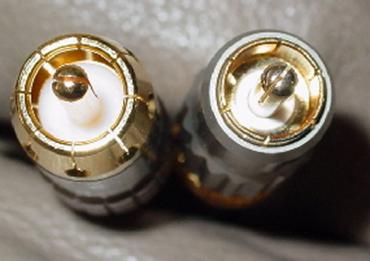
Note the differences in the RCA connectors in this picture. For starters, the gold plated inner conductors of both RCA's are the same, but the diameters of the RCA's ground shield are slightly different. It is noticeable by comparing the diameters of the white dielectric and the thickness of the shield. If you remember in Section 1.2, the inner diameter of the ground shield is approximately equal to the outer diameter of the dielectric. The diameter of the white dielectric in the RCA connector on the left is slightly larger than the diameter of the white dielectric in the RCA connector on the right. Don't be fooled by the gold covering of the dielectric on the right. The dielectric in this connector actually goes beyond that dimension. The critical outer diameter of the white dielectric is what defines the RCA connector's impedance, as defined in Section 1.2. It turns out that the RCA connector on the left has a very slightly larger dielectric diameter and is a bit more robust with the shield diameter, and is therefore a bit closer to 75-ohms, although not fully. Oddly enough, this manufacturer claims it is a true 75-ohm connection even though it can not meet the form factor. Audioholic's has contacted this supplier and made them aware of this discrepancy and we are awaiting their "measurements" to justify this claim, but have not see any to date. Regardless, the differences between the two are likely to be too insignificant to alter performance, especially with resistors in the circuit (DVD player and TV) absorbing most reflections. The fact is, both RCA connectors are adequate even though they are not true 75-ohms. There is truth to the statement that reflections due to impedance mismatch will increase substantially with much longer cables, but for the average 2-meter installation, it is not a significant issue provided it is a quality RCA and termination. The bottom line here is for long cable runs ( > 3meters), it would be wise to choose cables from a manufacturer that explicitly states the characteristic impedance of their cables is 75 ohms and not worry too much about the RCA connector impedance. Note that the electrical length of the RCA termination is significantly shorter than the actual cable itself. Thus at video bandwidth frequencies it's more important to maintain a 75ohm cable characteristic impedance then losing sleep over the RCA termination impedance.
Component Video Cables - The Definitive Guide - page 5
3.6 Protective Shields
As indicated in Section 2.1, EMI noise is around and at all times and can enter a component video cable and create interference. In theory, a long component video cable (2-meters or greater), acts as an antenna that can attract external noise. Conscientious manufacturers will implement features such as shields in coaxial cables to minimize EMI from entering. These shields should be made from nonmagnetic materials with thickness much less than skin depth at the frequency of interest. For coaxial cables, there are three basic shielding techniques, including foil shielding, braid shielding and combination shielding.
3.6.1 Foil Shielding
Foil shields are usually made of a thin layer of aluminum foil, bonded to a polyester film (for strength). A good foil shield allows for 100% coverage if applied with an appropriate overlap construction. Foil shields provide an easy termination and low costs, but are somewhat fragile. They are extremely effective in reducing RF noise, but not very effective in EMI (depending on the frequency).
3.6.2 Bi-Foil Shielding
The bi-foil shield is an aluminum-polyester-aluminum tape assembly that offers 100% coverage. There is two times the aluminum in this design as the foil shield discussed in Section 3.6.1, since aluminum is on both sides of the polyester film.
3.6.3 Bonded Foil
This foil is the same as the bi-foil construction, but it is bonded to the dielectric with an adhesive. It partially improves the shielding capabilities, but it is more for ease of cable assembly because the foil doesnât move or pull away from the dielectric when stripped.
3.6.4 Braid Shielding
Braid shielding was already discussed in Section 3.1.2. As mentioned in that section, the braided grounding shield is an effective shield for a wide range of EMI, but not within the RFI range.
3.6.5 Combination Shielding
This technique offers the best of both types of shielding. First a foil shield is placed around the dielectric, and then a braided (or two braided) shield is placed on top of the foil. This combination allows for blocking of a broader range of EMI, including RF noise. There are three basic methods of combination shielding such as triaxial, tri-shielding and quad shielding.
- Triaxial ö Braid-Separator-Braid construction
- Tri-Shielding ö Foil-Braid-Foil combination
- Quad Shield ö Foil-Braid-Foil-Braid combination
3.7 Jackets and Sheaths
Jackets or sheaths over coaxial cables act as a protective covering as well as contain the component elements and shields. Jacket materials are selected typically for cost, flame resistance, durability, flexibility, chemical resistance and to have a good appearance. The most common Jacket materials are as follows:
- PVC : PVC formulations vary widely depending on the desired properties. Because it is relatively inexpensive, easy to extrude and exhibits many excellent mechanical and electrical properties it is used for jackets on many component video cables. The disadvantage of PVC is its overall stiffness and lack of flexibility.
- Polyurethane : Polyurethane in general has excellent low-temp flexibility, high tensile strength, and long flex-life. It exhibits excellent chemical, water, and abrasion resistance, as well as being extremely tough and cut-through resistant. Polyurethane is extremely flammable but can be offered in a flame-retardant version at the expense of tensile strength and surface finish. Polyurethane is restricted to use in jackets only, due to its poor dielectric properties.
- Polyethylene : Polyethylene is the compound most widely used in coaxial and low capacitance cables due to its fine electrical properties. Although polyethylene is flammable, additives can be used to make the polyethylene flame retardant at the expense of the dielectric constant and power loss characteristics. Inherent properties make it ideal for direct burial applications.
- Nylon: Nylon exhibits excellent jacket toughness, especially in thin-wall applications, and has excellent abrasion, cut-through, and chemical resistance. Its main application is to provide these qualities when extruded over softer insulation compounds. Nylon has a very low coefficient of friction, making it a good choice for use in high flex applications. The disadvantage of Nylon is that it absorbs moisture, which, over time, can somewhat degrades the electrical properties of cable.
Component Video Cables Guide Conclusion
Conclusion
This article outlined the basic design principles and parameters used to design and help choose a component video cable. Based on the lengthy discussions in each section, marketing schemes such as the misuse of the term skin effect and the entirely made up term known as "strand jumping" were found to have insignificant deleterious effects on video cable performance. We also discussed differences between conductors (stranded and solid), differences in RCA connectors and how by their geometry, they can not be true 75-ohms as well as the lack of importance thereof, importance in shielding and techniques used during manufacturing, all of which are vital considerations in the design and build of a quality component video cable.
The fact is there is no substitute for sound engineering and manufacturing techniques for creating 75-ohm component video cables. Don't be fooled by too good to be true marketing claims that are abundant when considering the multitude of cables on the market. Use the information in this article as a general guideline in helping with selecting the cable that is within your budget and offers the best performance for the money.
Happy Viewing!
3/08/03: Component Video Cable - Revision C
This article has been edited to update the explanation of RCA connectors and how they can not be 75-ohms by their geometry.
1/29/03: Component Video Cable - Revision B
This article has been edited to clarify issues regarding wire gauge, skin effect and braided shields.
Peer Review - This article has been reviewed by the following helpful people.
-
Gene DellaSala - Electrical Engineer, HAA Certified Level 1
-
Mike Duda - Electrical Engineer Staff Member
-
Rick Rome - Custom Home Theater Installer and ISF Trained Technician, Staff Member
SOURCES
AV Cable
http://www.avcable.com
Madison Cable
http://www.madisoncable.com/
C & M Corporation
Dupont
http://www.dupont.com/industrial-polymers/elvaloy/loy_pvc3.html
Gore Electronic Products
http://www.goreelectronics.com/products/bulk_cable/Bulk_Precision_Coaxial_Cable.html
West Penn Wire
http://www.westpenn-cdt.com/newpdfs/T176o177.pdf
NAVAIR Weapons Division
https://ewhdbks.mugu.navy.mil/VSWR.htm
"Principles of Materials Science and Engineering" by Dr. Smith
"Electricity, Electronics, and Electromagnetics Principles" by Boylestad and Nashelsky.
"Data for Radio Engineers" published by Howard W. Sams & Co. 1975
"Noise Reduction Techniques in Electronic Systems" (Second Edition). by Henry W. Ott. Copyright 1988 by AT & T Bell Laboratories, published by John Wiley & Sons, Inc.
"Transmission Lines and Networks" by Walter C. Johnson
Gene manages this organization, establishes relations with manufacturers and keeps Audioholics a well oiled machine. His goal is to educate about home theater and develop more standards in the industry to eliminate consumer confusion clouded by industry snake oil.
View full profile