
Audiophile Myths About Amplifier Negative Feedback Debunked
Feedback is an ubiquitous and unavoidable basic technique that keeps the world running. It is only controversial in audio, and then only specifically in power amplifiers. As more respected manufacturers are coming out of the closet concerning their heavy and happy use of feedback, the myth is increasingly on the back foot. Here we present a pseudo-interview to help answer questions about feedback which is a fascinating and complex topic that lies at the core of successful design.
Q: What is Negative Feedback and what is it good for?
A: When you stand up without falling over, that’s feedback. Your inner ear has a kind of gyroscope that tells you where down is, and instructs your feet to move your center of gravity when it looks like the direction of down is changing. That’s combined with visual input from your eyes, so people whose inner ear balance doesn’t work can still stand up straight. That is, until they close their eyes and their feedback turns off. Then they keel over.
People use feedback constantly when they drive. You stay in your lane by looking at the lines and steering the car to stay between them. No sane person would suggest that driving with your eyes closed makes you a better driver.
Feedback is part of the physics of life. Paper planes only fly true because the slightest turn gets rewarded by an opposite push from the flowing air. Feedback just means that what is going to happen next is in some way influenced by what’s happened before.
Feedback is everywhere. All we do as engineers is use that perfectly natural phenomenon to help us get difficult stuff done.
Amplifier Feedback YouTube Discussion with Bruno Putzeys
Q: Like amplifiers.
A: Right. Let me guide you into this softly. Here’s an op amp gain stage, wired as a noninverting amplifier.
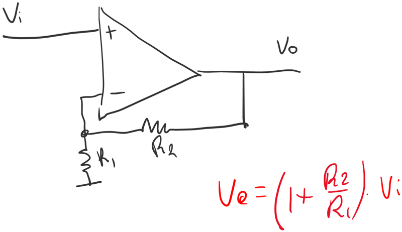
Do you remember this from school?
Let’s unpack this circuit for a bit. The plus and minus signs on the op amp symbol are shorthand to say that the voltage at the minus input is subtracted from the voltage at the plus input, and then amplified:
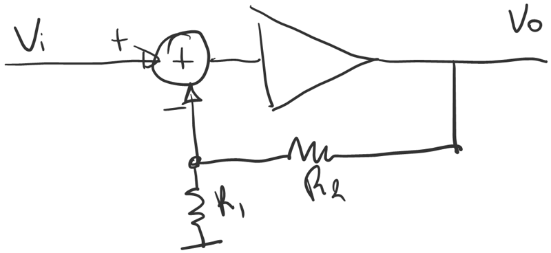
The circle with a plus in it is called a summing node. When there’s also subtractions taking place we’ll draw pluses and minuses next to the inputs to make that clear.
The two resistors form an attenuator. If the two resistors have the same value, the network multiplies the signal by one half. Let’s put that in a box too. A is the gain of the amplifier, B is the “gain” of the attenuator.
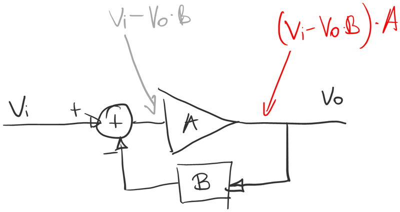
The grey formula says that the output of the summing node is the input voltage minus the attenuated output voltage. The red formula says that output voltage is that same thing multiplied by the gain of the amplifier. The number A is the “open loop gain” in control theory lingo.
Q: Let me stop you right there, I’ve heard some of this before and this is where engineers start talking about open loop gain, closed loop gain, and simply loop gain and they’re hoping we’re not going to confuse those three.
A: Fair point. We can call A gain before feedback.
We now have a formula for the output voltage Vo, but the expression itself contains Vo. That’s an equation and if we want to know what Vo is, we’ll have to solve it.

At school we also learned, for an op amp, to assume that A is infinite. With A just about infinite, the output of the summing node has to be just about 0. So the task of amplifier A is to steer the output voltage such that the voltage differential between the two inputs stays at zero. Like the driver’s task is to steer the car so that the difference between its position and that of the middle of the lane is zero.
When you do that, the one in the denominator becomes negligible and the output simply becomes the input times 1/B. That number, 1/B, is the gain after feedback (“closed loop gain” officially). 1/B=2 in our example of course.
That’s a first answer to your question: what is feedback good for. It allows us to build a circuit that does the precise opposite of whatever it is that you put in the feedback loop. That’s useful because with passive parts you can make an accurate attenuator but you can’t make gain. With transistors you can’t do a precise amount of gain but you can make a lot of it. Put the two in a feedback loop and you get an amplifier with a very precisely defined gain.
Same thing for filters. With resistors and capacitors you can only build half of all possible filter types. By adding an op amp you can now also do the other half.
Q: That doesn’t seem too evil to me and I don’t think many audiophiles mind feedback being used that way. Recordings are made with mic preamps, mixing desks and converters that are stuffed with op amps. The best DACs and phono stages use them.
A: Mind you, “op amp” does not have to mean “chip”. Some of the best op amps are still made from loose parts. But whether they’re made with discrete transistors or on a silicon chip, the op amp is the fundamental building block of all high performance audio circuits. But you’re right, most folks are happy with that when it comes to their signal source. It’s only when we’re talking power amplifiers that all of a sudden there’s a culture war going on.
Q: I guess they’d say that using feedback to control gain is one thing, and using it to reduce distortion is another.
A: Feedback always does both. When you’re building a filter, you want it to be independent of the tolerances in your op amp. It only works because feedback takes the op amp’s errors out of the equation. It doesn’t matter what you intended.
All you want a power amp to do is to gain up your signal as accurately as possible and nothing else. A linear power amplifier (by which I mean class A, AB or B) is just a discrete op amp with a bigger than usual power stage.
Q: Can you put the distortion into the picture?
A: Yes. Let’s make the power stage explicit and also add in the distortion created by the power stage.
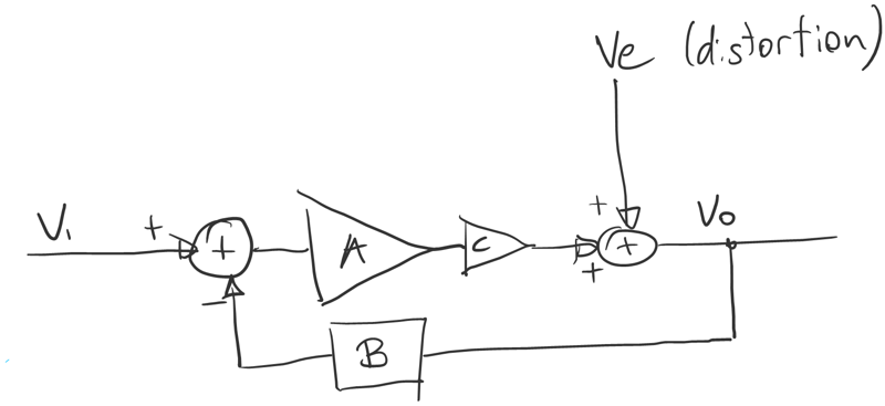
Normally speaking the power stage is a kind of follower circuit whose gain C is around 1. We treat the distortion as a separate input. It’s a simplification that makes it a lot easier to understand what’s going on.
Working backwards from the output we can write Vo by first adding Ve and then continuing through the amp, the input and then back to Vo through the attenuator:
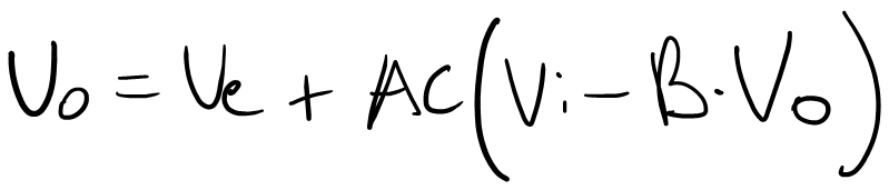
Move all Vo’s to the left:
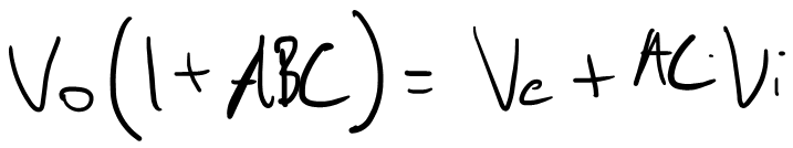
Divide both sides by 1+ABC and rearrange:
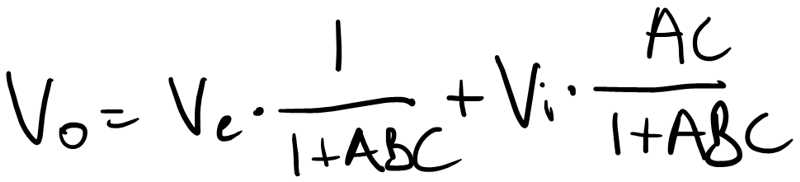
The result is what we had before, except we now also have a separate term with Ve in it. The output voltage is the input voltage times something plus the error voltage times something else.
That’s beautiful because it means that this circuit treats the input signal and the distortion differently. As A increases, Vi gets multiplied by something that gets ever closer to one over B. Meanwhile, Ve gets reduced by approximately A times B times C. This number (“loop gain”) is the amount of feedback.
Q: So where’s the bad news?
A: The bad news is that making A large is not trivial. It is a bloody hard problem in fact. This analysis only shows is how wonderful life would be if A were large. It doesn’t say how.
That’s where reviewers and armchair experts go wrong. They think feedback is an easy fix, a cheat almost. All you need to do is crank up A real high right? Sure, all you need to do to win the London Marathon is to run really fast and keep going. Go tell that to Sir Mo Farah.
Q: Sorry- just explain, what’s so hard about adding gain? If you can’t make an amp with enough gain, can’t you just add another one?
A: Have you tried that?
Q: I have.
A: Did it work?
Q: No, it went unstable.
A: Bingo.
Feedback responds now to what happened before. It’s about time.
The output stage isn’t infinitely fast. If you don’t want the feedback loop to overreact, you want the gain stage A to react gently at first and only add further course corrections when it sees the power stage respond.
Control systems engineers like to use simple signals to test the stability of a feedback loop. A step function, say. We perturb the system with a Ve that jumps from zero to one and then stays there. Then we watch the system steer the output back to zero.
Q: That sounds reasonable. After all, the distortion must first happen before the feedback loop can do something about it.
A: And ultimately it can’t respond any faster than it can command the output stage.
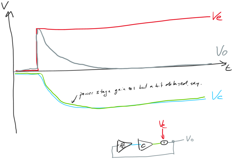
I’ve pared the circuit down a bit. I’ve removed the input signal and the summing node with it. Then I’ve combined the gain of the attenuator into the amplifier triangle alongside the minus sign from the summing node. It’s called negative feedback for a reason.
It’s not a terrific drawing but I’ve tried to show there’s a delay between the power stage’s input and output. Because of that delay alone, the gain stage A needs to respond gently at first.
What kind of circuit does this? Let’s remove all traces that aren’t directly connected to the gain stage A:
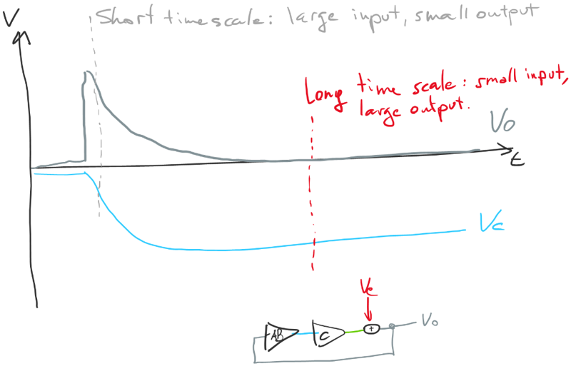
At a short time scale, a large input only produces a moderate output. Over the short run, A is small. But after a while a nearly zero input produces a sizeable output. So over the long run A must get quite large.
Another way of saying this is that fast, high frequency swings are amplified much less than slow, low frequency swings.
We call a circuit like this an integrator, symbolized by that weirdly elongated S.
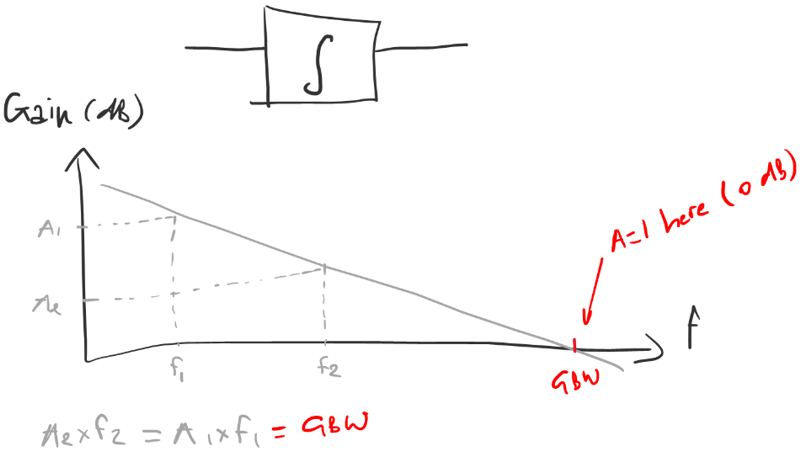
The frequency response of an integrator drops by a factor 10 every time the frequency goes up by a factor 10. On a dB scale and a logarithmic frequency scale we get a straight line that slopes downward by 20dB per decade. Or, less accurately, 6dB per octave. That’s saying that whenever you multiply a frequency with the gain you get at that frequency, you always get the same number. That includes the frequency where the gain is 1. That frequency is called the Gain Bandwidth Product.
Q: That number will tell us how quickly the distortion gets compensated I assume. But it doesn’t take away the fact that at t=0 the distortion went unchallenged entirely.
A: Whatever happens, stays happened. Very fast or high frequency errors don’t get corrected.
Here’s what the loop does to distortion:
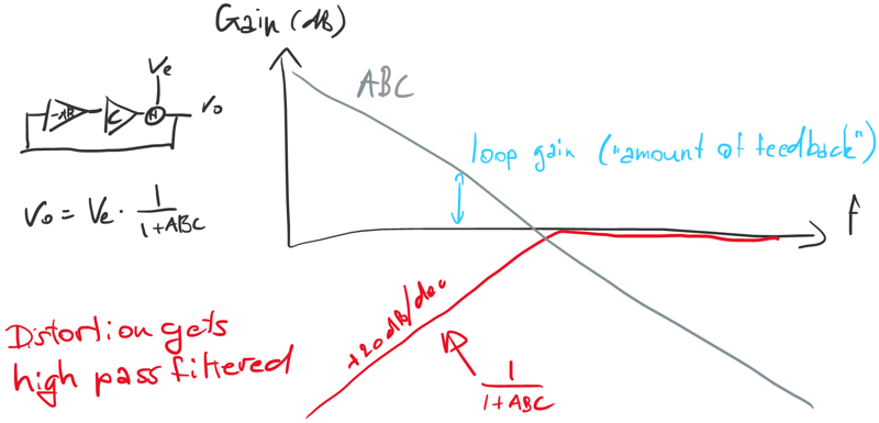
We can still use our old equations, so long as we remember that the numbers A and C (and in some cases B) are frequency dependent, so you need to calculate it for every frequency and make a plot. Then you find that the distortion ends up high pass filtered.
The amount of feedback is not a single number but one that drops with frequency. That’s important when you’re trying to relate how much feedback an amp has with how it sounds.
Q: Well I did notice that a lot of amps show a rise in distortion as frequency goes up.
A: Actually all of them do. The game is to try to keep distortion as low as possible in the audio band. Real distortion isn’t super fast so to a degree the loop has some time to catch up with it while it happens. But the basic fact remains that A has a natural tendency to come down with frequency and I for one have a natural desire to make A as large as possible.
The problem is that we can’t just push GBW. GBW has to stay below the bandwidth of the power stage or we risk overreaction or worse, instability. So far I treated C like it was 1 for simplicity’s sake but it isn’t. I’m still simplifying but let’s say the power stage is a first order lowpass filter:
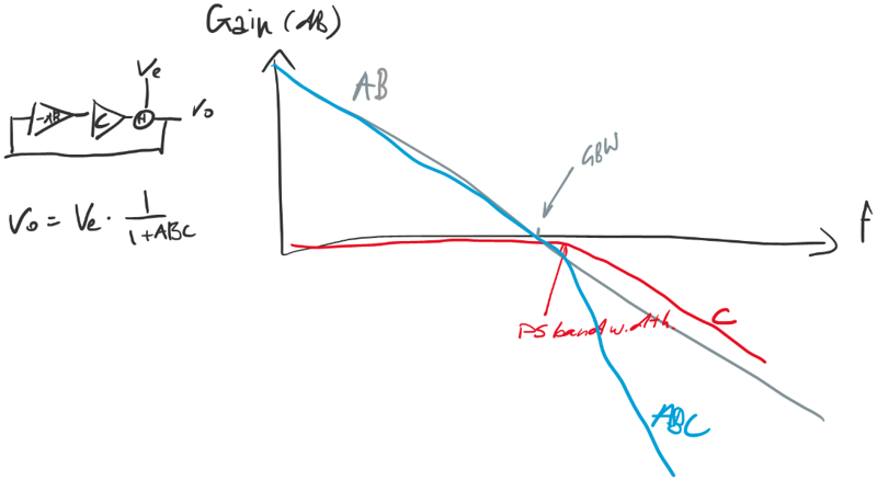
The point where the combined gain ABC goes from a first order slope to a second order slope should be below unity gain, otherwise the phase shift will tip the circuit into oscillation.
Q: What I don’t get is this. Power transistors in the 70’s were slow. And you’re basically saying that if the power stage isn’t fast, you can’t get a lot of feedback. But it was exactly in the 70’s that you’d see these amps with ridiculously large amounts of feedback.
A: No you didn’t. That’s where it all went pear-shaped. The confusion was really simple. Here’s a typical gain plot for those days:

People would look at the number on the left of the graph and say wow 80dB that’s a lot. But hang on, you barely get 20dB at the end of the audio band. That’s not much at all.
Reports of amplifiers with lots of feedback in the 70’s were Bigfoot sightings. “I’ve seen an amp with a ton of feedback and I’ve got a fuzzy photograph to prove it.” People thought they were listening to a high feedback amplifier, didn’t like what they heard, concluded feedback was bad and a myth was born. By the start of the 80’s, it was gospel.
Q: Huh.
A: 80dB at 20Hz is trivial. 80dB at 20kHz, now that would have been an achievement. It would also have corresponded to a GBW of 200MHz.
Q: A 200MHz power stage wouldn’t even be possible today, would it?
A: A handful of headphone amps come close, but for a serious power amp it’s not on the cards.
Q: Is a lot of feedback even possible?
A: It is, but speeding up the power stage is only going to get you so far. We need to get out of the GWB straitjacket entirely.
We said that feedback high-pass filters the distortion. But does it have to be first order? Can’t we make that a second order? Well seen from that angle it’s not a hard one to answer. Just take that formula 1/(1+ABC) we had earlier and equate that with a second-order high-pass filter. Solve for AB, and see if you end up with something you can build.
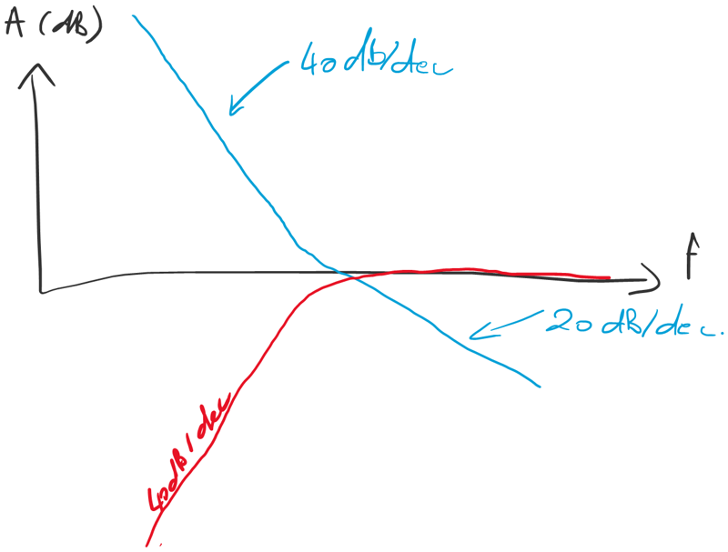
Conceptually we start by imagining we’ve solved the problem, that we’ve got an amplifier that filters distortion according to the red curve. That only leaves us to work out what’s inside. How much feedback does it need to produce that behavior. The answer is the blue curve. It has a second order slope, which is no surprise. But somewhere before it hits unity gain it slows down to a first order slope. I didn’t need to invent this. It’s just what the math says it should do. Now build it and Bob’s your uncle.
Audiophile Myths About Amplifier Negative Feedback Conclusion
Q: But how do you know this thing will be stable?
A: Because we’ve started off asking for a stable high-pass response. The calculation tells us that if that’s what we want, then this is the circuit we need to build. You build it, and you get the exact response you were asking for. I know “phase shift” and “stability” are trigger words for some people. But only if they start with a circuit and find out what it does afterwards. This method takes out the guesswork. Just work backwards from the result you wanted. Ask for a stable amp, you get a stable amp.
Q: I’m not sure I’ve heard that approach anywhere before.
A: It’s the standard way for people who design sigma-delta A/D and D/A converters. It’s so normal there that most of them don’t even care about how much feedback they’ve got. They only care about the high pass filter response, which in their lingo is called the Noise Transfer Function. You can have a whole career in converters without ever noticing you’ve built something that has a lot of feedback and that could be useful for power amplifiers.
Q: One thing keeps nagging me. Just a while ago you said the phase shift can only be allowed to increase once you’re below unity gain. But here you’ve got the entire stretch above unity gain that’s second order.
A: Actually the only place where you should keep phase shift down is at unity gain. Above it you can have as much as you like, and below it as well. This has been known in control theory since 1932. They call it the Nyquist Stability Criterion.
Q: This stuff is textbook?
A: Yeah, just not in hi-fi.
Q: So what does this look like as a circuit?
A: Here’s one way to build this gain function:
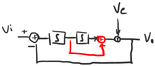
You start by cascading the two integrating amplifier stages together. But that gives you a second order slope all the way down. You still need to knock the order down to first order at high frequencies. So add a by-pass that takes over at high frequencies. At low frequencies you see both integrators. At high frequencies you only see the first.
Q: I told you I tried cascading stages and it went unstable. You’ve just solved a mystery for me.
A: Don’t fret it. It’s not the most obvious way of doing a second order loop anyway and you’re not the only one. Folks thought that global loops with multiple stages were impossible for just that. So the marketing department stepped in and changed the story to say that global loops were “bad for sound” and that designers “choose to use only little global feedback combined with local feedback”.
Which boils down to this:
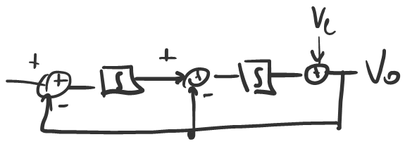
First you build a local loop round the power stage. That still gives you power stage with a gain of 1, but with less distortion. Then you put a second loop around it. This is called a nested loop. You can see it does exactly the same as the previous version. In this case it’s the first integrator that gets bypassed by the local loop connection.
Q: Well that I recognize. Local feedback round the power stage combined with some global feedback. Don’t most amps work like that nowadays?
A: They do. This nested circuit is much more intuitive and has the bypass built in. Amplifiers with “a bit of global feedback combined with local feedback” constitute the majority of highly respected linear workhorses. And they sound great!
Their secret is that they aren’t low feedback amplifiers at all. You take a bit of local feedback and a bit of global feedback. You put them together and what you get is no longer a bit of feedback. It’s a substantial amount. But their manufacturers choose to hitch their cart to the feedback myth by claiming these amps have less feedback than Bigfoot. No they don’t.
Call me an idiot for trying to swim upstream and use the fact that I use prodigious amounts of feedback as a sales argument. But it’s what makes or breaks an amp, and has been for decades. Why hide it? Frankly I think the real suckers are the ones that bought into the myth and started new companies to make amps that explicitly avoid feedback.
Q: Can you take it further than second order? Where does it stop?
A: Most linear amplifiers stop at third order, by combining a local first order loop with a so-called two pole compensation in the global loop.
By linear amp standards more than third order is getting a bit hardcore. But it’s bread and butter stuff for sigma-delta folks. High order feedback loops only started turning up in power amplifiers because people with a converter background started turning their attention to class D, skipping linear altogether. Make no mistake: high order loops are more easily applied to linear amplifiers than class D. It’s just that nobody is waiting for an improved diesel engine. My claim to fame is getting these very high order loops sorted in class D. Making a 7th order global loop work smoothly is really hard but it is worth it.
Q: I take it the feedback myth hasn’t really caught on in class D circles then.
A: Generally, no. Our memories are too fresh. Back in the 90’s, getting the first feedback loops to work at all, and then to close that loop after the output filter were major milestones. It was only then that class D started sounding like amplifiers and became recognised as a viable alternative to class A.
But that know-how is not in the public domain. Now that class D has a good public image, new people are trying to get in on the act but they’re 20 years behind the curve knowledge-wise. So lately a few companies have turned out class D amps that look like a complete throwback. No feedback, or pre-filter feedback only. You can bet the feedback myth figures heavy in their marketing. Sex up the circuit with Gallium Nitride FETs and presto, perfect press bait.
Q: I guess you’re saying that you can make the feedback loop more and more complicated and the results keep getting better and better. But more expensive too, and I guess quite a few people would argue that we’re already well past the point where it’s going to matter for sound. So when should you say it’s good enough?
A: Adding an order of feedback costs practically nothing in terms of added parts. There’s only the investment in time working around the increasing number of quirks of high gain circuits. A clever feedback loop can get distortion down several thousand times for a few bucks worth of components. It just doesn’t pay to ask the question when’s it good enough, and go through the hassle of endless listening tests if you can just shoot for a point that’s clearly way better than needed.
The only reason why it’s difficult to bring super high end performance to the end customer at a budget price is economy of scale. It’s only going to happen when a really big company decides to do this.
That’s a huge contrast with zero feedback amplifiers. You need to improve the power stage and power supply, and that’s expensive. Every single part ends up affecting the result. Some even think it’s a matter of pride that they’ve tweaked the sound of every flipping resistor in the circuit until it struck some sonic balance. I call that spreading the dirt evenly.
I’m not saying it’s totally impossible to make a zero feedback amplifier with acceptable fidelity, but you can never make it good value for money.
Q: Does negative feedback cause TIM? Might some amplifiers with lots of feedback not cut it sonically because of that?
A: Oh that old chestnut. I’m not sure why that keeps coming up. Maybe the commentariat thinks TIM is something spooky that they can baffle the scientists with? For those people I have bad news. TIM is not mysterious. Its source is precisely identifiable. It is easy to understand for anyone with a passing interest in amplifiers. It’s easily measurable.
It’s going to get technical again but I promise there’s a payoff to this. Let me pull up a circuit sketch of a linear amplifier.
Q: Sorry to butt in but why should you, of all people, choose to explain TIM with a linear amplifier?
A: Because class D amplifiers don’t have TIM! It’s that specific. TIM is a kind of distortion that happens in the differential input stage of linear amplifiers that follow this topology:
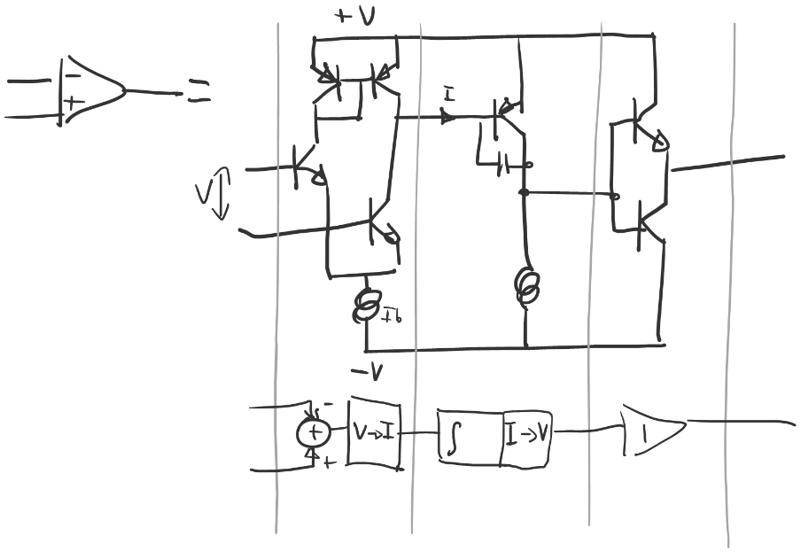
This is as simple as I can draw it. It doesn’t matter whether we’re talking about a small op amp or a power amp, the basic circuit is the same. You get three stages. The first is a differential input. It takes a voltage and turns that into a current. The second stage is an integrator. It uses the current to charge a capacitor. That produces a voltage again and that’s buffered by the output stage.
The gain we’ve called A is the product of gains of the first and second stages.
The input stage works by splitting the tail current Ib over the two input transistors. The pair above are wired so that their base voltages are the same and their collector currents are the same too. This is called a current mirror. So a copy of the collector current of the left input transistor is added to the collector current of the right input transistor. When the bias current splits evenly, the combined output current is 0. As soon as you get an input voltage, the split becomes unbalanced and the difference flows into the capacitor in the middle stage.
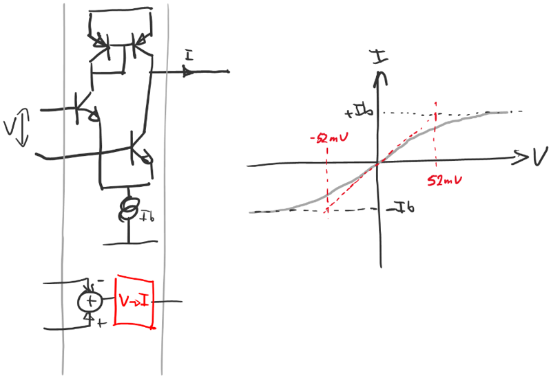
The input stage isn’t particularly linear. It’s an S shaped curve of which only the middle few millivolts are reasonably straight. A symmetrical and smooth nonlinearity like that, you can approximate as so many times the input plus so many times the input cubed. That cubed part, that’s going to be our distortion and it’ll show up as a third harmonic.
Let’s rearrange the block diagram a bit and combine the gains of the first and second stages together, and leave only the nonlinearity in its own box:
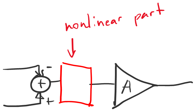
To work out how much distortion happens at the input, we need to know the input voltage. For that, you don’t need to know anything about the feedback loop.
Q: You have no feedback loop but we already have TIM?
A: Correct. To a first approximation the output voltage is simply the intended output voltage, which is close enough to understand what happens next. From the expected output voltage of your amp you find the expected (distortion-free) input voltage by dividing by A. Then you add in the distortion term.
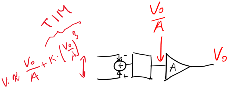
When we do close the loop, the distortion of the input will turn up, alongside the input signal, amplified by the closed-loop gain (gain after feedback). The feedback loop doesn’t cause TIM but it won’t help fix it either.
That makes TIM so nasty: it is added to the input signal. It’s not inside the feedback loop and doesn’t get filtered. It’s all over the spectrum. We’re not talking about some subtle form of colouration. We’re talking about obvious crackling and spitting when the amp is pushed. The sound of TIM is nothing like the wine tasting terminology of audio reviewers. It’s nasty, brutish, goes from 0 to 60 and back in the blink of an eye. It screams at you suddenly and then it’s gone again. If you’re expecting to use TIM to explain some sonic finesse of a power amp playing a string trio, trust me, you’ve never heard TIM.
Now look closely at the TIM distortion term. It is proportional to the cube of 1/A. Now suppose I managed to increase gain-before-feedback by a factor 10 somehow:
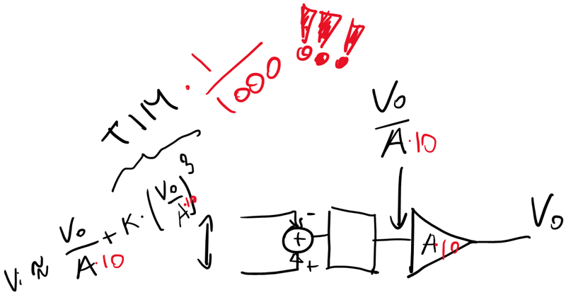
That’s TIM knocked down by a factor 1000.
Q: I can see why you’d consider that ironic. You increase gain-before-feedback and get a disproportionate reduction in TIM. So you’re making feedback bigger and get less TIM.
A: Funny old world, innit? The myth that feedback causes TIM is not just inaccurate or wrong. It’s the exact opposite of the truth. You don’t often get engineering truths that tidy and simple.
If your amplifier has TIM, it means that you have tried but failed to get a lot of feedback. Tried, because you’ve equipped it with the kind of differential input stage that only handles tiny signals. Failed because you’ve managed to overload it.
That gives you a handy shibboleth for when someone’s bending your ear about feedback at a party. Simply ask them “does feedback cause TIM”. If they say yes, you can safely ignore whatever else they might have to offer on the topic.
Q: Why is it called TIM?
A: If A is inversely proportional with frequency, TIM is proportional to frequency cubed. So it’s mostly associated with sharp transients. The chap who first mentioned this and called it Transient InterModulation was Matti Otala from Finland. He designed a test that could separate input stage distortion from other frequency-cubed sources. TIM is not really the name of a type of distortion but of a test method that seeks it out. It mixes a sine wave with a square wave. The Transient part refers to the edges of the square wave, the Intermodulation to the fact that the distortion product actually turns up below the input frequency. It was all about showing you can’t just ignore the input stage in this kind of circuit. Folks just thought that it was an indictment of feedback in general.
You can find TIM in data sheets but nowadays we call it DIM. It’s a standard part of the test protocol and not esoteric at all.
Q: But is it at least true then that too much negative feedback can be a bad thing if implemented improperly? Are there examples of such products on the market?
A: The short answer is no. If you can do a ton of feedback and keep it stable, well done. But quite often you see feedback loops that fail to realise all the potential benefits.
Nested loops in linear amps for instance. TIM happens when the amp hasn’t got enough gain before you close the global loop. A local loop around the power stage doesn’t change what the input stage sees in terms of signal. So nested amps need to mitigate TIM separately, for instance by adding local feedback around the input stage.
In class D amps one of the most audible sources of distortion is the output filter. If you only take feedback before the output filter, the scope for improvement is quite limited. Taking some feedback before the filter and some after is also an unnecessary compromise.
Q: So the notion that local feedback is better than global…
A: … is the exact opposite of the truth, yes.
Q: Is it true that increasing negative feedback lowers low order distortion at the expense of higher order distortion (which is more audibly detrimental)? If true, is the answer that it’s a nonissue if all distortion is sufficiently low? How low is low enough?
A: If you’ll forgive the Briticism, “yish”. As in “yes-ish”. But the grain of truth is really tenuous.
To explain I need to remove Ve and replace it by an actual nonlinearity. Here’s a unity gain amplifier made with a summing node, a gain stage and something that produces distortion wrapped in a unity gain feedback loop. The distortion is a transfer function of the type Vout=f(Vin).
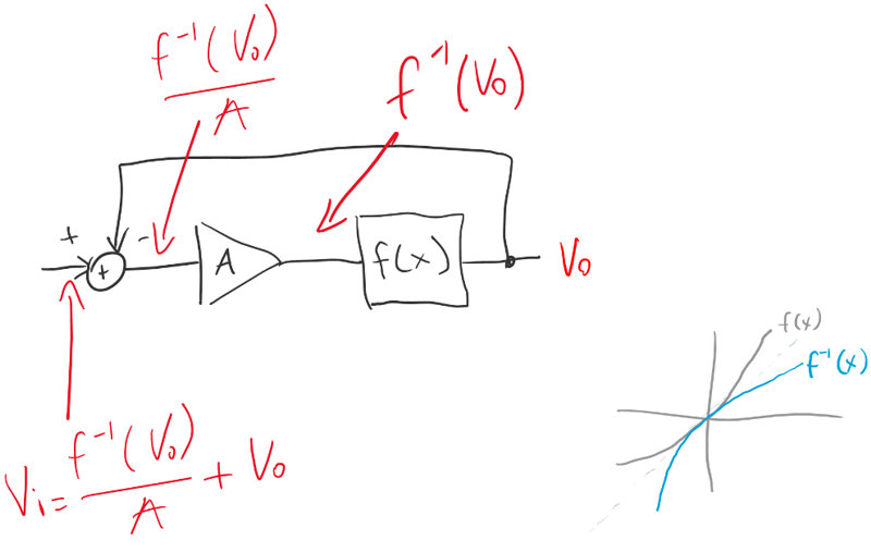
Again we’ll work backwards. Assume you already know the output voltage. What voltage appears before the distortion source? It’s the inverse of the nonlinearity applied to the output signal. At the input of the gain stage we find that same value, now divided by A. Finally, to get to Vin at the input of the summing node we need to add the output back in.
If A is sufficiently large, the output voltage will be nearly equal to the input. Equal enough that we can substitute it for Vo in the argument of f-1:
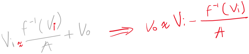
The result indicates that when you use a lot of feedback, it works as expected. You have a distortion component and the bigger you make A, the smaller the distortion gets. The only unexpected part is that the distortion is not the original distortion, but its inverse.
Q: That’s fairly academic in my opinion. I don’t think the inverse of some distortion is going to sound much different from the original distortion.
A: I’d generally agree. Still you can construct an interesting lab curiosity if you can contrive a circuit whose f(x) has no higher harmonics. Say f(x)=x2+x. That only produces second order distortion whereas its inverse is f-1(x)=sqrt(0.25+x)-0.5. That square root has higher harmonics including odd ones. In an extreme case like that, feedback will make those harmonics appear out of nowhere. If your aim is to make feedback look bad, that’s exactly the type of example you’ll pick.
The mistake they make is to suggest that these higher harmonics keep growing as A gets bigger. That’s wrong of course because once the distortion has flipped around, it just stays like that. So for the sake of the argument, if you did have a perfect second order nonlinearity the worst thing you could do is to apply just a little feedback. Higher order components turn up well before you get a net reduction in distortion.
Q: Suppose your original f(x) was a square root? Would that mean that higher harmonics would quickly drop away as it feedback causes to flip it over into x squared?
A: Absolutely! But you don’t see people use that example because it would defeat their purpose.
Q: I think you’ve eviscerated just about every technical argument I’ve heard against feedback in audio amplifiers, and then some. Is there really nothing there that counts against it? Maybe something you’ve only told your wife about?
A: Honestly, no. At the end of the day, I don’t enjoy looking at measurements. I listen to music, like any other audio nutter. I have ears and I use them. And what I hear is a steady improvement every time I find a new wheeze to get more feedback. The music just gets more emotional and more tangible. If that weren’t the case I’d be off like a shot trying to find a reason but as it stands, there’s no mystery waiting to be explained as far as feedback is concerned.
Summary of Key Talking Points about Amplifier Feedback
 Feedback is a natural process that happens all around us. Engineers have learned to use it to solve many difficult problems. Building precise amplifiers and filters are some audio related examples.
- The central myth about feedback is that it's easy to pile on more at will. This is only true at subsonic frequencies. Higher up the audio band every dB of feedback is hard fought for.
- The proverbial 70's amp that had lots of feedback only did so at low frequencies, but had very little left at high frequencies. Unfortunately they used a type of input stage that only works properly if you really do have a lot of feedback. That caused TIM.
- Increasing global feedback quickly produces a massive reduction in TIM. This is the exact opposite of a widely circulated myth.
- Nesting local and global loops is the most common way of increasing feedback. Almost all modern class AB amplifiers work like that. They are not low-feedback amplifiers, even if they're often marketed as such.
- Full global feedback is not easy but is technically superior to nested or partial feedback.
- Feedback theory is highly advanced in the field of Sigma-Delta AD/DA converters. Methods developed there are also often used in class D amplifiers.
- Feedback flips the shape of the distortion over. This can turn a distortion with few higher harmonics into one with more higher harmonics or vice versa. In practice the effect is only significant in lab curios specifically built to demonstrate the effect.
- Feedback is one of the most effective tools to improve sound quality. Although the R&D outlay can be substantial, using feedback barely affects the cost of the circuit.
