
Subwoofer Placement - The Place for Bass Part 1
Subwoofer placement...
A. Theory
Where it comes to fine-tuning a home theater sound system for peak performance, finding those locations within a typical home listening space where a subwoofer can provide the most satisfying response - across every seat in the designated listening area - is one of the perennial challenges facing both enthusiast and pro alike.
Two of the main players in this challenge are as formidable as they are indispensable: the boundaries enclosing the listening space and the energy-storage ability of the air enclosed by those boundaries. Together, these two components largely, though not entirely, define the listening space's unique acoustic identity.
Experimentation is key and in a practical sense, there exists no perfect location. Rather, you'll likely find that the final location chosen for your subwoofers represents the best solution drawn from a collection of well-prioritized compromises. Compromises that arise not only as a consequence of the room's acoustics, but also from aesthetic as well as other, practical, considerations, such as WAF (wife approval factor) or SAF (spouse approval factor). In some households, the WAF or SAF are moot points. In others, they are variables not to be trifled with. Such is the lot of Audioholics everywhere.
Here in Part I of "The Place for Bass" we'll look at the challenging process of placing two subwoofers within a listening space. The technique presented here doesn't require any sort of measuring device other than your ears - which I will further assume work correctly - or the possession of anything more than the most basic sources of test signals, such as, perhaps, a CD with appropriate test signals or music CDs with lots of repetitive bass runs. If you do have gear capable of doing accurate dB SPL measurements, certainly feel free to put it to use; for those of you who do have measurement gear, though, you might find Part II of this series more applicable.
We'll begin by looking at the energy-storage ability of the air bounded by the four walls, floor & ceiling.
Eigenmodes
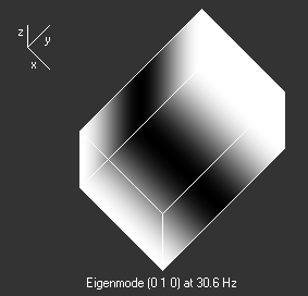
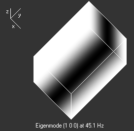
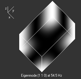
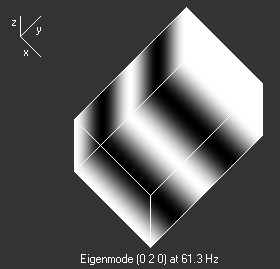
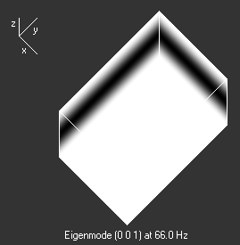
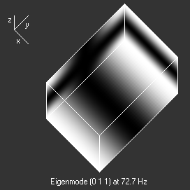
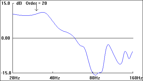
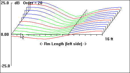
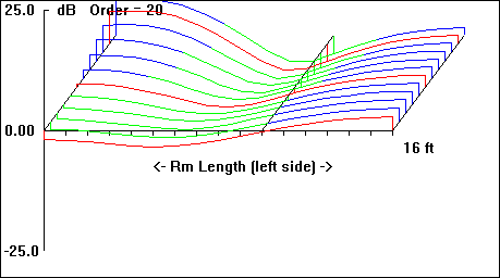
The acoustic wave field that sets up within the air enclosed by the listening space can be decomposed into linearly-independent modes that oscillate in time at distinct frequencies. These modes are called eigenmodes, room modes or standing waves (N = 010, 100, 001, 020 …) and the frequencies are accordingly called eigenfrequencies or room resonances (Hz).
For the test room modeled, with dimensions of: W = 3.5m, L = 5m, H = 2.5m, I ran a series of simulations to work up a rough estimate of the eigenfrequency values (in Hz) and the spatial, sound pressure distribution for each eigenfrequency setting up in the room. The results are presented in Table 1, Figs. 1 through 20:
|
Figure 1 |
Figure 2 |
|
Figure 3 |
Figure 4 |
|
Figure 5 |
Figure 6 |
|
Figure 7 |
Figure 8 |
|
Figure 9 |
Figure 10 |
|
Figure 11 |
Figure 12 |
|
Figure 13 |
Figure 14 |
|
Figure 15 |
Figure 16 |
|
Figure 17 |
Figure 18 |
|
Figure 19 |
Figure 20 |
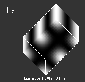
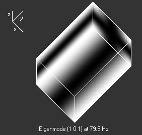
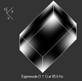
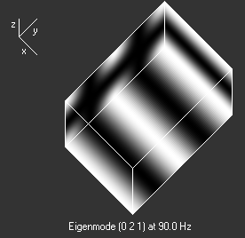
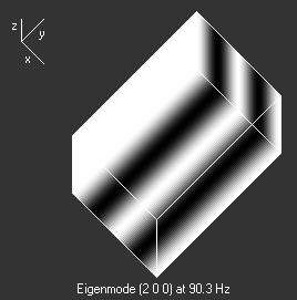
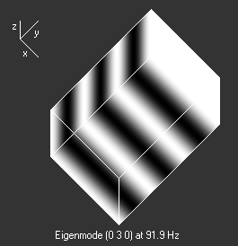
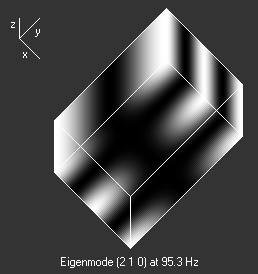
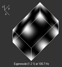
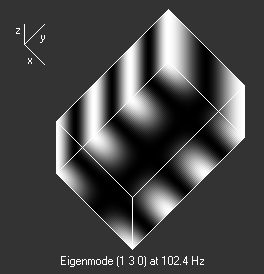
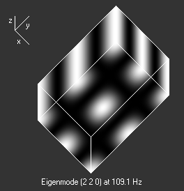
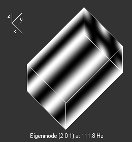
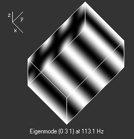
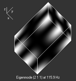
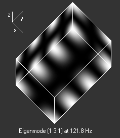
Table 1: Spatial distribution and relative amplitude of test room resonances
In this series of images the brightest regions represent the resonance's antinodes. Conversely, the black regions represent the resonance's node spatial disposition. Together, they graphically depict the interference patterns setup by the incident and reflected waves at the various eigenfrequencies. Note how the corners appear again and again as mode 'hot spots'. Presented graphically, it's pretty easy to get an idea of the spatial distribution of room resonances. But how do these resonances set up in a room in the first place?
Using the half-space model (Fig. 23 - system bolted flush into one wall) as an example, imagine for a moment that the subwoofer is emitting an acoustic wave whose length, λ, (m or ft) is twice that of the room's longest dimension. Under this condition, the movement of the driver's cone will be in phase with the reflected signal coming back from the opposite wall and as a consequence, sound pressure quickly builds up, shortly reaching maximum amplitude. The amplitude is characterized as an equilibrium point between energy supplied by the subwoofer and energy absorbed by the boundaries & enclosed volume of air. So how do these resonances affect sound as perceived at the listening position?
Single Subwoofer Placement and Boundary Effect
Imagine, as shown in Fig. 21, at one end of your listening room, located on the center axis of the room and 1 meter out from the wall directly behind it, sits your subwoofer. At the opposite end of the room sits you, on the same central axis of the room and seated a meter away from the wall immediately behind you.
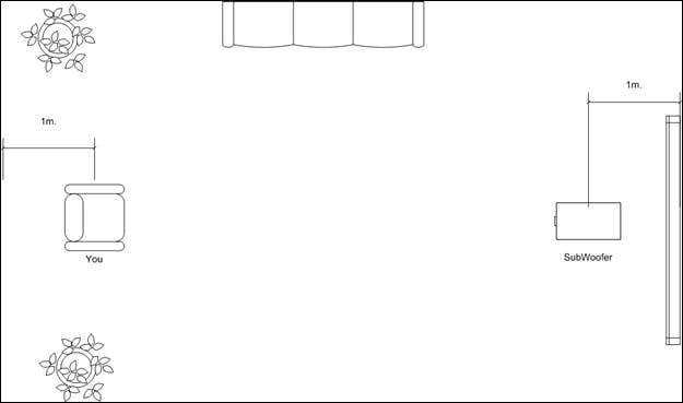
Further imagine, for the sake of discussion, your subwoofer has an on-axis amplitude response that measure perfectly flat, anechoically. Now let's fire up the subwoofer.
Once the subwoofer's energized, the first sound that reaches your ears is the direct sound, with the systems dead-flat frequency response intact and unaltered by the room's acoustic signature.
At the same time, sound is, of course, traveling in all directions, including those areas where the room modes are formed. Reaching those areas, it then excites the mode or modes, which store the energy, then release it, after a delay. That energy then continues its transit of the room's enclosed volume, eventually reaching your ears, delayed behind the first-arrival sound, and with amplitude altered. If the resonance decays at a rate such that the primary sound event ends before the resonance decays to a sub-audible level, than the LF portion of the audible spectrum begins to sound, subjectively speaking, "loose" or "poorly defined".
The net effect is that you now perceive the subwoofer's response through the "lens", as it were, of the room's acoustic signature and the perceived frequency response now features all the evidence of the room's resonances: peaks & dips that in some circumstances can reach 10s of dBs in magnitude.
Of the three types of modes (axial, tangential & oblique) that can set up within a listening space, it's the axial modes (e.g.: Figs., 1 & 2) that will have the most noticeable effect on perceived system response at the listening position. The degree to which any of these discrete, LF modes, affect the perceived response depends largely upon the location of the listening position and the location of the subs within the listening space.
These room modes don't require a special type of signal set up: sine wave, pink noise, music or a hand clap: so long as energy is applied at the correct, required frequencies the mode will be excited. It does not require a steady tone. On the other hand, if the acoustic energy applied to the listening room's space is at a frequency where no mode exists, no resonance sets up, thus no effect on the perceived response at the listening position; there's no frequency-specific modal energy build up in the space.
Room resonances truly are resonant systems: they have a specific Q ( the ratio of energy stored by the reactive components of the resonance - mass and compliance - to the energy dissipated (absorption, etc), bandwidth & characteristic natural frequency. Their amplitude depends upon the excitation period and their duration depends upon the absorptive qualities of the walls, floor & ceiling and the volume of air enclosed by the boundaries.
Boundary Effect
Along with room resonances, the effects of the room's boundaries play a key role in determining the subwoofer system's response as perceived at the listening position.
For this portion of the analysis I ran a series of simulations using a vented subwoofer, sporting a single 12" driver, with an amplitude response characterized by -3dB points at ~14Hz and ~80 Hz. For reference I'll start by modeling the system in both 4π steradian (full space) and 2π steradian (half-space) domains. We'll be using the 2π steradian system response as our reference measurement.
With the front panel of the subwoofer modeled flush with the radiation boundary (which illustrates the half-space model) and the source of acoustic energy being small compared with the wavelengths being radiated (not forgetting the low pass -3dB point is set at 80 Hz), the effects of diffraction & increasing directivity will not be seen in the response. As expected, it behaves like an omnidirectional radiator bolted in to a wall of infinite linear dimensions.
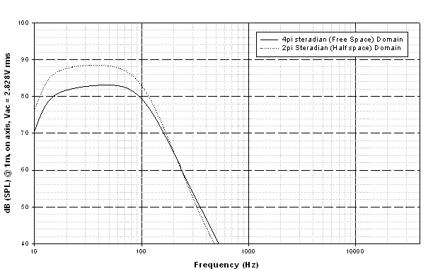
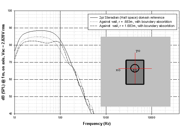
Having established a 2π steradian (half-space) response of the system as a reference point (as seen in Fig. 22) we can now exam the effect of boundaries on system response.
In Figure 23 we see the cabinet positioned such that its back panel is flush against a wall. No other boundary effects are presented in the simulation. The simulation is then re-run, this time with the cabinet moved 1m away from the wall. The "r" value is the distance from the system reference point (the center of the faceplate) to the boundary located immediately behind it. .683m is also the depth of the system's cabinet, therefore when r = .683m, the back of the cabinet is situated flush against the boundary immediately behind it. Please note that in these simulations, as the cabinet's position is changed, the listening position of the microphone changes accordingly, thus maintaining the 1m, on axis orientation of the mic.
Single Subwoofer Placement and Boundary Effect pg2
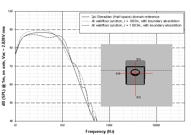
In the second simulation (Fig. 24) we see the results of locating the system at the juncture of 1 wall and the floor, first at r = .683m, then at r = 1.683m. No other boundary effects are considered or present in the analysis. As in the preceding simulation, the effect of boundary absorption is factored in to the analysis.
In the third simulation (Fig. 25) the system was placed squarely in a corner and as before, first at r = .683m, then at r = 1.683m. In this case, the effects of two walls and the floor, along with boundary absorption, factor into the system's response.
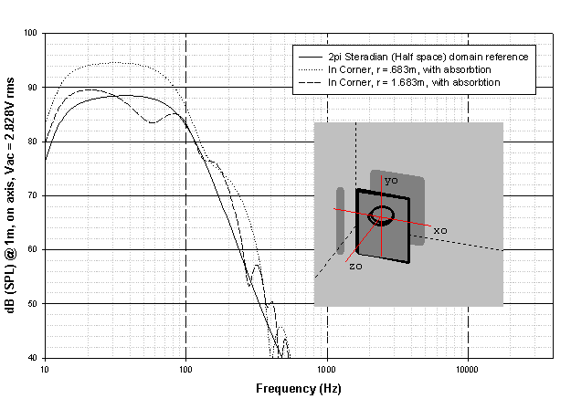
The power output of an acoustic energy source, such as the subwoofer modeled here, is a function dependent upon both the acoustic volume current and the resistive component of the radiation load. The magnitude of the resistive component of the radiation load is inversely proportional to the solid angle (4π, 2π, π, π/2 … steradian) of space into which the subwoofer fires.
We see the end results of this in the simulations: the power radiated into half-space (2π-steradian solid angle) is twice that which is radiated into full space (4π-steradian solid angle). Further, we see the increases in dB SPL levels we go from half space (2π-steradian) to quarter space (π-steradian, floor/wall junction) and finally to π/2 steradian space (in the corner). All of which nicely illustrates why pushing your subs into a corner increases the perceived output of your prized wall-shakers. (Note that this effect occurs in that portion of the frequency spectrum where the system's dimensions and boundary distances are small when compared with the wavelengths under consideration, eventually decreasing with increasing frequency).
At the frequencies we're dealing with when speaking about subwoofers, we can consider them to be omnidirectional radiators quite capable of exciting every room resonance whose eigenfrequency lies within the system's pass band.
Locating your subs for maximum bass slam and doing so by taking advantage of the room boundaries (especially corner placement) can work. Be aware, though, that given the very complex nature of any average listening room's acoustics - and the fact that there exists significant output at wavelengths possibly smaller than some or all of your listening room's dimensions - you'll be altering the measured or perceived amplitude elsewhere in your system's response spectrum. For example, you will likely see a dip in response at that frequency which has a quarter wavelength equal to the distance from the acoustic center of the subwoofer's driver to any of the room's boundaries. Once again, experimentation, in this case, with subwoofer placement will quickly tell you what works and what doesn't.
Subwoofer Positioning and Crossover Adjustment
I. Positioning
For this section, I'll assume: (1) You have nothing other than your two healthy ears to assess your listening room's acoustical signature; (2) unless otherwise noted, you are running signal through nothing other than your 2 subs; (3) you have a collection of applicable test signals sufficient for you to determine at various stages the nature of the sound you perceive at the listening position and how the room is affecting that sound; and (4) all appropriate, preceding tasks necessary for calibration of the rest of your audio system have already been accomplished.
Note: If you do have at hand appropriate gear capable of making accurate time or frequency domain measurements, feel free to use it as/when needed. I'll be treating the topic of subwoofer placement based on in-room response measurement techniques more in-depth in Part II of the Place For Bass.
Sub calibration can be divided into 5 steps:
1. Subwoofer position adjustment.
2. Listener's position adjustment.
3. Adjustment of phase between subs & mains.
4. Parametric equalization
5. Subwoofer gain matched to that of the rest of the system.
I've seen a few different methods used to systematically identify an optimal disposition for multiple subwoofers within a single listening space. Here's one such method, chosen for its thoroughness.
It's a highly iterative process and you may find yourself getting bored of listening to the same thing over and over again. Allow for breaks along the way to alleviate the boredom and help minimize the chance of listener fatigue creeping into your impressions.
Make notes at each and every step along the way; use diagrams; include sufficient detail that you'll be able to back-track should you find your current collection of placements/settings doesn't sound anywhere near as good as something you had worked up half an hour ago. Remember, you're dealing with quite a few variables here. Keeping track of everything can help make the process run that much more quickly.
1. Mask off the entire floor of the listening space into small squares 2' - 3' feet on side. Locate this masking-tape grid in such a way that each seat in the listening area is contained within its own square. If you're concerned with leaving behind any sort of tape residue on the floor, use those masking tapes specifically formulated not to leave any sort of gummy residue behind.
2. Work up a spreadsheet that will allow you to systematically record your listening impressions for each square you audition, given a particular subwoofer set disposition. It's too easy to forget your impressions across multiple trials not to make the effort to record your data.
3. If possible, move those seats located in the listening area out of the way and locate both subs in the center of the listening area, typically positioned on the central axis of the room's longest dimension.
4. With both sub's gain all the way off and their phase switch set to 0°, your processor's subwoofer equalization set to flat, play back your test material through the LCR mains and increase the gain on both subs till you just hear their presence in the mix. Then push the gain up a bit further, then back down to the point where once again you just hear them in the mix.
Don't worry about any sort of final fine tuning at this point: here all you need to do is get a reasonable, working playback level from your subs. Once that level has been set, turn off all channels, save those feeding the subwoofers. I'll assume at this point that your sub's crossover frequency has been set at or near 80 Hz.
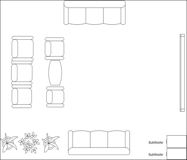
5. Set your CD or DVD transport to loop and then listen at each square, noting your aural impressions.Immediately, you'll notice some squares give a more balanced impression than others. Note accordingly in your spreadsheet. Once you've listened at every square, go ahead and move the subs along the axis you've chosen further apart than you had originally placed them. Then make the circuit around the room again, visiting each square and again noting your impressions, making careful note of those squares which sound particularly good or bad. It won't take long before patterns emerge. Repeat as necessary until you are satisfied you have placed your subs correctly. (Feel free to use Figures 26a through 33a as possible dispositional templates). Finally, make note of the best sounding squares for each sub position you try. It's from that list
you'll draw the final choice of subwoofer location.
6. Having identified those squares in the room where your performance criteria have been best satisfied, move the subs to those positions and commence your listening tests, this time, walking the squares where the seats making up your listening area are ordinarily located. At this point, you may find shifting the seats a bit further improves the sound of your subs in the listening area. If you are constrained from moving the seats in your listening area by the walls, other objects in the room, objecting spouse, etc you can, of course, go ahead and skip this step.
7. Once you have settled on a location that represents "best possible", for both seats and subs, bring all other channels back online and re-adjust the subwoofer gain, if necessary. Remove the masking tape from the floor otherwise you run the risk of plummeting S or W approval factor!
II. Crossover Adjustment
8. The 80 Hz lowpass crossover frequency mentioned in Step 4 may be what works best for your system in your listening space, but if you need to change that or you're just interested in experimenting with a new setting, here's a quick way of finding that new set point. For this adjustment, you'll need the mains & subs running. (If you plan on running the mains set to "Large" run this test sequence with them set likewise, if your processor will allow for it).
With you seated in the listening position, have an assistant dial the processor's subwoofer lowpass frequency all the way down until the subs & mains sound clearly separate in terms of the what portion of the audible spectrum you hear pouring out of them. Then have your assistant dial upward the sub's lowpass frequency until that point where your ears tell you that you've reached the point of smoothest or most seamless splice between subs & mains.
I've seen this technique implemented using both music and pink noise. Once you've settled on the frequency that sounds best to you, move to another seat in the listening area and repeat the test. You should eventually reach a consensus where it comes to the best crossover frequency overall. When you reach the Equalization stage, you may find it necessary to re-adjust the crossover frequency.
Subwoofer Phase Delay and Equalization
III. Phase / Delay Adjustment
9. You may find that adjusting the phase setting (typically done at the subs themselves or at the processor feeding them, if necessary) further smoothes an otherwise uneven main/sub splice. Experiment will quickly show whether an improvement occurs or not: you may hear more or less bass for a given phase setting. As simplistic as that sounds, altering phase has a truly complex effect on the perceived characteristics of a room's acoustic and thus the sound you perceive at the listening position. Making phase adjustments must be approached with the understanding it can do as much harm as good.
Having said that, with you listening from a variety of positions within the seating area, have an assistant, adjust the phase or polarity setting for one sub (leaving the other off)and listen for what setting sounds best. Then do likewise for the other sub, with the first one shutoff. Finally, with both subs on, adjust further, but only if necessary. You may find repeating this test with a variety of test media of further help.
Although delay adjustment can serve a variety of purposes, I include it with phase adjustment simply because as you alter delay, you alter phase. Delay can also be thought of as an electronic means of establishing subwoofer placement symmetry or minimizing path differences between the subs and the listening position.
Delay can effectively be used for a variety of purposes, in both consumer and pro audio. Some find that ignoring phase settings altogether and focusing instead on delay adjustment works best. In the context of subwoofer integration, delay can be used to ensure that the direct sound from both subs & mains arrives at the listening position at the same time. Knowing the speed of sound, you can quickly determine the time of flight differences (and thus the amount of delay) between signals for many subwoofer arrangements, but how would you calculate for arrangements such as those showing in Fig 39a?
For that particular case, assume the front sub & LCR are arranged (or calibrated) such that their signals arrive at the seating position simultaneously. Calculate the time (in ms) or distance (in feet or meters) of flight from the front sub & LCR locations to the listening position as well as that from the rear sub to the listening position. Subtract the latter from the former, then apply the resulting delay value to the rear sub.
For example, suppose your LCR main/front sub cluster is 5 meters from the listening position and the rear sub is 1meter from the listening position. 5 m - 1m gives a flight distance difference of 4 meters. You would therefore need 4 meters delay on the rear sub. In that way, direct sound from the LCR main/front sub cluster and the rear sub reach the listening position at the same time.
IV. Equalization
10. Equalization. Approach this one with caution: it can create as many sonic problems as it solves, especially when misapplied. There are some things this processor can do very well and some it does poorly. And there are things it simply can't do at all. Be aware of its limits and remember, it's the direct sound of the subwoofer you're equalizing, not the room!
Before proceeding, here are a few cautions worth keeping in mind. An equalizer is a frequency-domain electrical device that cannot correct time-domain acoustical problems. As well, no analog EQ can correct for steep, high-Q dips in a response, so you'll be focusing on flattening or otherwise lowering any response peaks.
Over the years I've seen a variety of techniques used for setting up an equalizer without any sort of measurement gear at hand. Here's one of the more efficient approaches I've seen. I'll assume for this segment of the set up process you're using a parametric equalizer. A parametric equalizer (PEQ) is preferable when fine-tuning your sub's performance as you can adjust gain, Q (or reciprocally, Bandwidth) and frequency. Together, they allow you to more effectively target those portions of the low frequency audio spectrum that need alteration.
By this point in the setup process, you've already done quite a lot that hopefully has improved the integration of your subs with your system's mains. You've gotten to know the space quite well and if you've kept notes along the way it should be clear at this point what acoustical problems remain. With your PEQ bands zeroed out, begin playback of your test material and listen for any noticeable remaining peaks in response. (If needed, repeat this test for every seat in your listening area). If you haven't already, at this point you'll likely identify one particularly noticeable resonance, followed by a few others, present, but less pronounced.
We'll focus on the most noticeable resonance first. This part of the procedure should be done with both subs & the mains on. Select an appropriate band pot and dial (or key in) in a modest boost, say +3 to +4dB, and a fairly sharp Q. Then slowly sweep up, then down, the frequency scale; you're listening for that frequency where the boost is most noticeable. You may have to do this a few times.
Once that frequency of max. boost effect has been identified, you've targeted the resonance frequency. Slowly lower the gain at that frequency until the peak disappears and instead assumes a balanced, natural sounding position within the test media's spectral mix. Now vary the Q value until the sound you are hearing sounds even more balanced or natural. Re-adjust the gain as necessary. Do the same adjustment process for the other, lower-amplitude resonance frequencies until you are satisfied. Now listen from all the other seats in the listening area, starting with those nearest your first listen test location.
The purpose here is to determine a consensus or acceptable compromise in perceived response across all the seats in the listening area. This may not be at all possible to achieve . Indeed, you may find that an acceptable level of performance is achievable at only one seat within the listening area. Following the above approach, however, maximizes the probability of finding the placement\settings solution that optimizes subwoofer performance. It uses a bare minimum of test media, your ears and if you like, appropriate measurement gear.
In the Part II of Place For Bass, I'll look at a hardware-based measurement approach to optimizing subwoofer performance that will assume the end user has at hand both signal-generation as well as appropriate measurement hardware.
If this setup sequence has helped bring your system to a level of performance you're happy with, its time to raid the snacks cupboard, grab a collection of your favorite beverages, cue up your favorite flicks and enjoy!
Dual Subwoofer Placement for Two Subs
In this section I've provided a collection of sub woofer dispositions you may find helpful in figuring sub placement. The collection features some traditional locations as well as those research has shown to be of value and therefore worth considering.
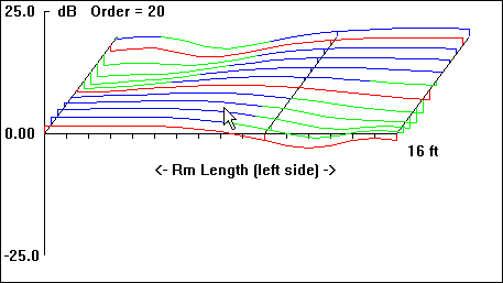
The graphs included with each plan view of the hypothetical listening space are first-order approximations of the sub's perceived amplitude response at the listening position as well as room-mode response at a given frequency (30 Hz, in each case, as indicated by the down arrow in all "b" graphics).
Being first-order approximations of room mode behavior, they do not include the effects of many other acoustical variables present. As such, they serve to give only a general picture of the relative merits of the various dispositions.
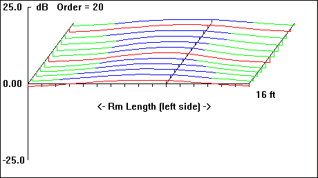
I. Subwoofers Placed in Same Corner
II. Subwoofers Placed Diagonally
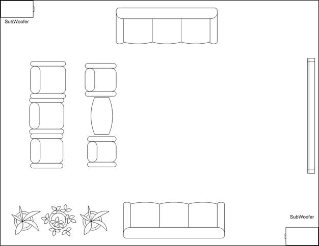
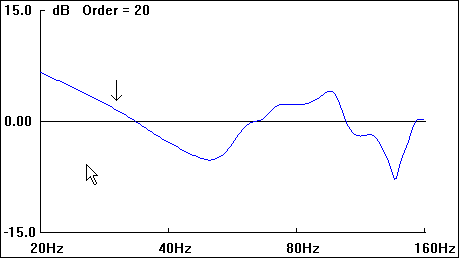
Figure 27b
Dual Subwoofer Placement for Two Subs p2
III. Subwoofers Centered Along Side Walls
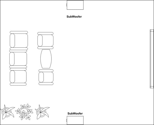
Figure 28 a
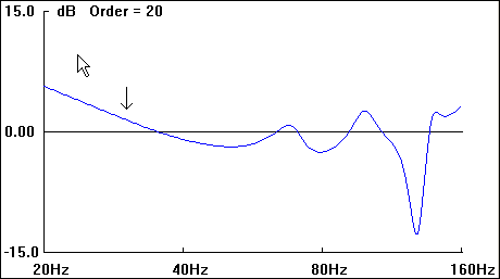
Figure 28b
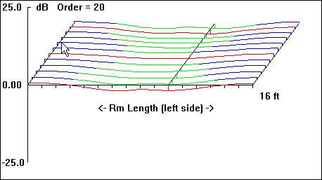
Figure 28c
IV. Subwoofers Centered On Front & Back Walls
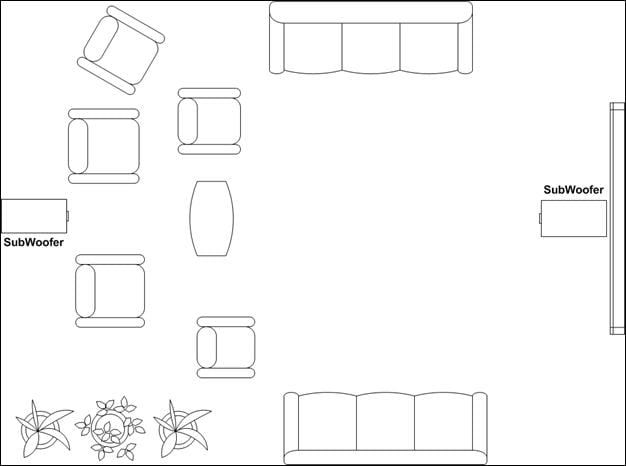
Figure 29a
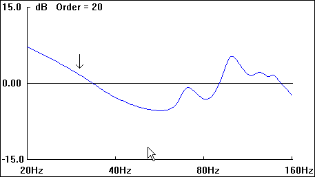
Figure 29b
Dual Subwoofer Placement for Two Subs p3
V. Subwoofers Aligned Center of Side Walls and 25% Inward from Side Walls
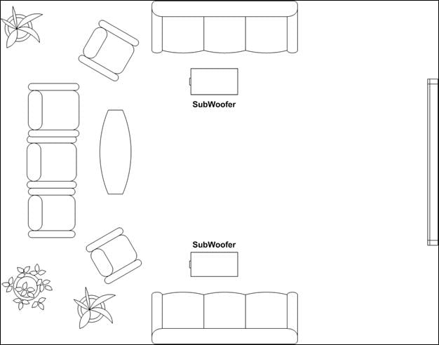
Figure 30a
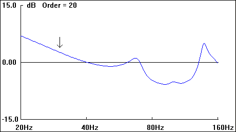
Figure 30b
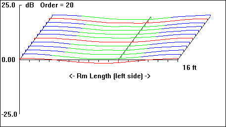
Figure 30c
VI. 1 Subwoofer Placed in Each Front Wall Corner
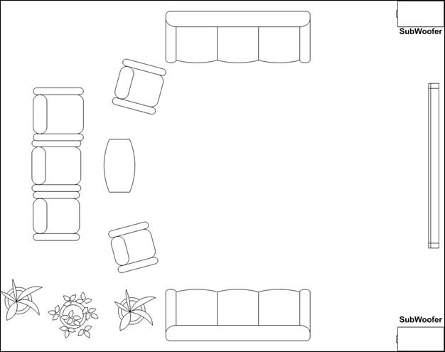
Figure 31a
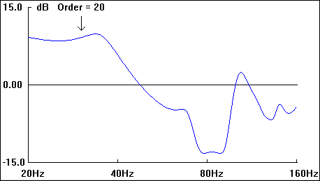
Figure 31b
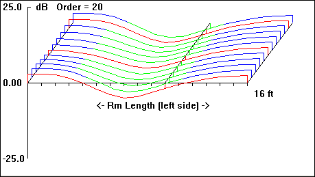
Figure 31c
VII. 2 Subs, Placed Near L & R Mains
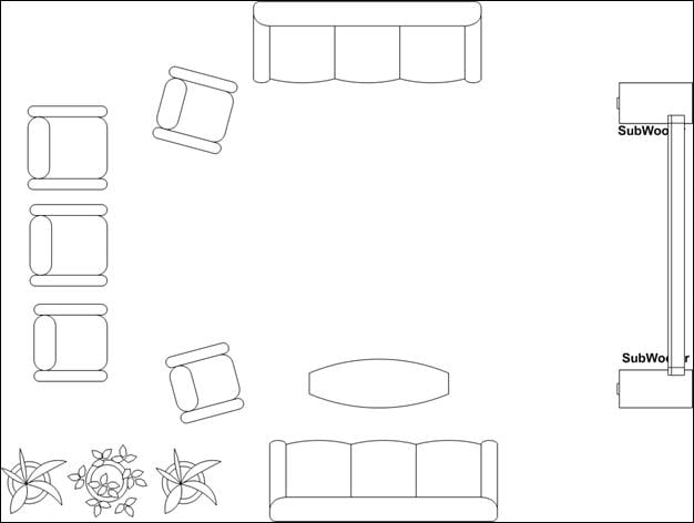
Figure 32a
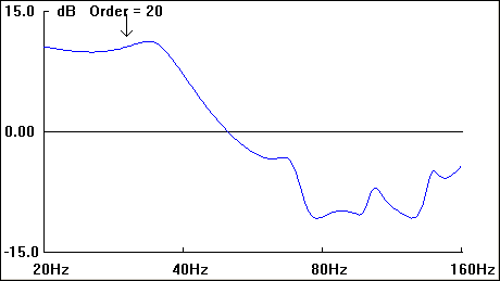
Figure 32b
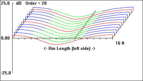
Figure 32c
Subwoofer Placement Bibliography
VIII. 1 Subwoofer Placed in Front Corner
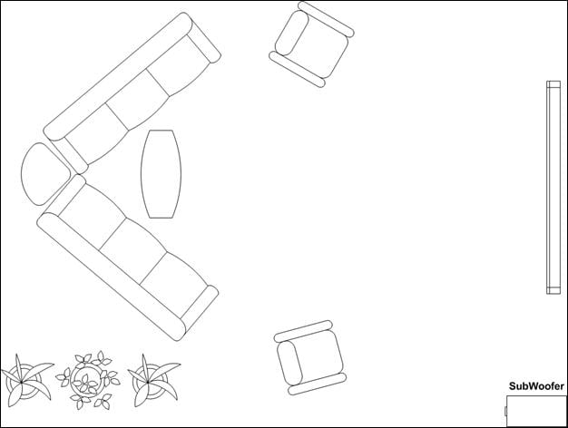
Figure 33a
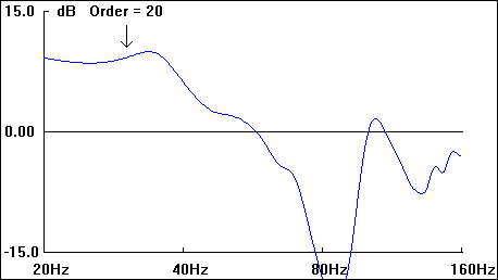
Figure 33b
Resources
Allison, Roy . F.: " The Influence of Room Boundaries on Loudspeaker Power Output ", Journal of the Audio Engineering Society, Vol. 22, #5, June, 1974 .
Moir, James: " Loudspeakers In Rooms: which response ", Hi-Fi News & Record Review, June, 1982.
Strahm, Chris: " Complete Analysis of Single And Multiple Loudspeaker Enclosures ", Audio Engineering Society Preprint, #2419 (D-1)
Berger, Russell, E.: " Speaker/Boundary Interference Response ", Mix, Vol. 8, #8.
Gander , Mark, R.: " Ground-Plane Acoustic Measurement of Loudspeaker Systems ", Journal of the Audio Engineering Society, Vol. 30, #10, October, 1982.
Walker, R.: " Acoustic criteria and specification ", R & D White paper, WHP 021, British Broadcasting Corporation, Research & Development, January 2002.
Walker, R.: " An preliminary investigation into the measurement of time and frequency response of listening rooms and control cubicles ", Research Department Report, British Broadcasting Corporation, Research Department, Engineering Division, May, 1979.
Walker, R.: "Low-frequency Room Responses: Part 1: Background and qualitative considerations", Research Department Report, British Broadcasting Corporation, Research Department, Engineering Division, August, 1992.
Fielder, Louis D., Benjamin, Eric M.: " Subwoofer Performance for Accurate Reproduction of Music ", Journal of the Audio Engineering Society, Vol. 36, #6, June, 1988.
Olive, Sean E. et. Al.: " The Effects of Loudspeaker Placement on Listener Preference Ratings ", Journal of the Audio Engineering Society, Vol. 42, #9, September, 1994.
Zacharov, Nick, et. Al.: " The Use of Subwoofers in the Context of Surround Sound Program Reproduction ", Journal of the Audio Engineering Society, Vol. 46, #4, April, 1998.
Mäkivirta, Aki, et. al.: " Low-Frequency Modal Equalization Of Loudspeaker-Room Responses" Audio Engineering Society, AES, 111th Convention, September, 2001.
Howe, R. M., et. al: " Methods of Local Room Equalization and Their Effect Over the Listening Area", Audio Engineering Society, AES, 91st Convention, October, 2001.
Figures 25, 30a, 31a, 32a, 33a, 34a, 35a, 36a, 37a, were drawn with the energetic & enthusiastic assistance of my daughter, JB.