
History of Multi-Sub & Sound Field Management (SFM) for Small Room Acoustics
Dr. Floyd Toole Theater Room
The problem with the small rooms we listen in at home, and recording control rooms of comparable size, is that they so often present us with offensive bass booms, and the bass is different at different seating locations. Over the years audio enthusiasts and audio professionals have attempted to tame these room resonances by different means, fiddling with room dimensions, system layout, etc. but the fallback, and often the only practical solution was low-frequency absorbers, currently better known as bass traps. These are inherently large, and need to cover a significant percentage of the interior room surface to be effective. They damp the resonances by removing energy from the sound field, reducing constructive-interference peaks, and reducing the destructive-interference dips, thereby somewhat smoothing the frequency response and damping time-domain misbehavior: ringing.
In professional circumstances these are taken for granted. In homes, things are not so simple. Dedicated audiophiles may be able to justify, even be proud of, the visible evidence of attention to good sound, but many people demur. To be most effective these large objects have specific locations to address problematic room modes, which may put them where a door, a window, a fireplace, anything, is in the way, so there are purely practical considerations. Although the wife-acceptance-factor (WAF) is often trotted out as a stumbling block, let us not be sexist − I truly believe that many men care about visual aesthetics as well. I certainly do.
Finding a Practical Solution to Fixing the Bass
This is a story of how I grappled with this issue. As you will learn, the matter gets to be very personal when one’s own system and home are involved. The old expression: “Necessity is the mother of invention” was at the root of much research. I did some and with input from some talented engineers, new insights into the problem of bass in small rooms have been revealed and some alternative solutions are now available.
Chapter 13 of my book (“Sound Reproduction: Loudspeakers and Rooms”, Focal Press 2008) discusses the science of this in detail, with references to papers that contain even more.
To begin at the beginning. In the late 1970s, when I was a young research scientist in the Acoustics Section of Applied Physics at the National Research Council of Canada, in Ottawa, I was just getting serious about doing research into sound reproduction, a field that had been neglected by science, and was showing signs of being led astray by opinions and folklore – it still is to a disturbing extent. We had superb measurement facilities, but to parallel this technical data, and to enable insightful analysis of it, I needed comparably trustworthy subjective evaluations. For this a room was required, and a good-sized lab across the hall from my office was available. I took it.
Being a professional laboratory space, it had a concrete floor and plaster on block walls, built, I suppose, to contain the fire and explosive forces of a mad-scientist experiment gone wrong. Without treatment, the bass was monstrous in both quantity and quality. The solution was low-frequency membrane/diaphragmatic absorbers, bass traps, which I designed and built. I managed to build one absorber into a wall, but the others perched as 4” to 6” deep, 4’ x 8’, boxes on the hard plaster walls, located in high-pressure lobes of the offending standing waves. Visual aesthetics were unimportant; only performance mattered, so all was well. They did their job, along with carpet, drapes and scattering furnishing in bringing the reflectivity, measured as reverberation time, into the range of normal domestic rooms and taming a couple of overactive modes.
The listening tests being done in this room were intended to parallel what might be heard in normal homes, by consumers of the products being evaluated. In wood/metal-frame construction a single layer of drywall on studs is a useful low-frequency absorber – if you feel the bass in the floor or wall, it is removing energy from the room modes. Without built-in absorption some must be added. The illustration below, Figure 21.7 in my book, shows the difference between one and two layers of drywall on the interior surface of wood stud walls. Obviously, the less massive and stiff the walls are, the more energy is removed from the sound field; speakers will work a little harder, but some amount of damping has occurred and resonances will be less obvious. The boundaries of the room are acting as membrane absorbers; the same happens with bass traps. Sound energy is converted into another form, movement and frictional losses, usually ending up as heat. Absorbers are, by definition, lossy devices – sound goes into them, and not all of it comes out. The name “trap” says it all.
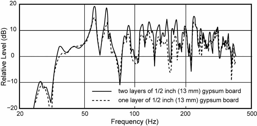
Figure 21.7: Level (dB) vs Frequency Response of Room Comparing 1 layer to 2 Layers of Drywall
In any event, the new listening room sounded good, providing early data in my subjective/objective correlations of loudspeaker performance. In fact it was sufficiently well respected that it became the prototype for the International Electrotechnical Commission (IEC) standard listening room documented in IEC Recommendation 268-13 (1985). It is described in the Appendix of my paper “Listening Tests – turning opinion into fact”, J. Audio Eng. Soc. Vol.30, 1982.
In this same time period, as a moonlighting activity, I designed a few recording studios, including one ground-up design that was large enough to accommodate a 75-piece chamber orchestra, plus drum and vocal booths, and control room. Needless to say, frequency-selective absorbers and sound scattering surfaces were extensively used. In the control room I even designed the built-in monitor loudspeakers, after claiming that I could do better than the then-popular designs – I won the challenge. The point of this tale is that I was conversant with the design, fabrication and use of frequency-selective absorbing devices long before they began to be called “traps”. I was also intimately familiar with recording studio practices and preferences.
Problem One: my first seven-channel home theater, ca. 1988
A few years later I was confronted with a room in our new home that boomed intolerably. The normal solution would have been to install low-frequency absorbers, as I had done at the NRCC. Analysis of the situation revealed that to attenuate the offending resonances would take a significant number of these devices and because the room already existed, they could not be built into the structure as might be possible in a new construction. My wife and I like art, paintings and sculpture, so visual aesthetics matter. We also had a great panoramic view, and large floor-to-ceiling windows existed where some of the absorbers would most logically be located. This was not going to work.
I took it as a challenge to find a more acceptable solution. An analysis identified the problem room modes and indicated that it should be possible to attenuate both of them by using two subwoofers in the right locations. This is shown in Figure 13.22 in my book, shown below, with before and after steady-state frequency responses and waterfalls. By placing the in-phase subwoofers in opposite polarity lobes of the offending modes they were substantially cancelled. This left only a narrow interference dip, and the "boom" went away, leaving impressively tight bass. Note that in (e), the waterfall shows that there were two closely spaced modes (width and length), as is evident from (a), and that one of them decays very quickly from T=0, and the other is attenuated by more than 10 dB before it decays somewhat more slowly. The frequency resolution of the waterfalls was 25 Hz and the time resolution 40 ms, thus enabling the decays to be seen. However, the lowest frequency measured is also 25 Hz and this, combined with low-frequency background noise means that events at very low frequencies in these graphs are not accurately displayed. However, the notion of a bass “transient” at 20 Hz is something best discussed over several glasses of your favorite alcoholic beverage. Remember, superimposed on these decays are the decays of musical instruments. Drums and bass guitar sounds have significant duration and ringing of their own. However, the real information is in (b) which shows no evidence of problematic modes when both woofers are operating.
I was both pleased with the result and proud to have "discovered” an alternative solution. These data were presented at the AES 8th International Conference: The Sound of Audio in a paper entitled “Loudspeakers and Rooms for Stereophonic Sound Reproduction”, Paper number 8-011, in 1990. To my knowledge it was the first time anyone had used multiple subwoofers to attenuate room modes.
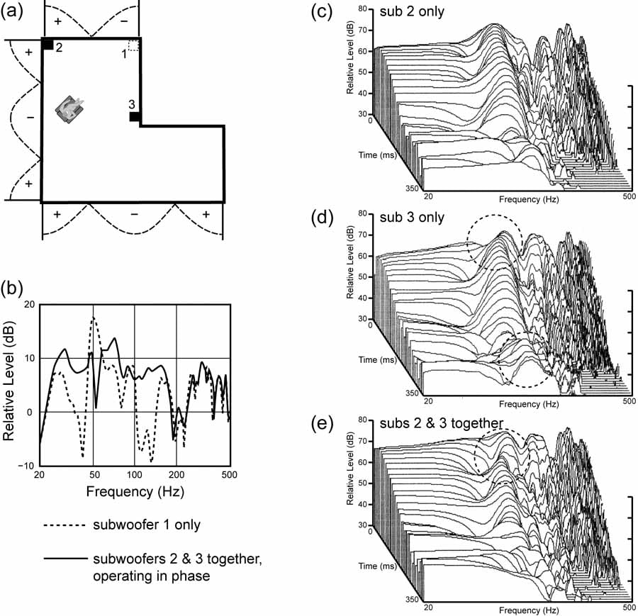
Figure 13.22: Floyd Toole Family Room Sub Positioning and Corresponding Measurements
But were the modes eliminated? Yes, but only when the sound system was running, and only for the sounds radiated by it. Turn the system off, pick up a bass guitar and the offensive modes are back. So, if the room is to be a performance space, either for recreation or a recording studio, the electroacoustic mode canceling is useless. Build or buy some bass traps and get on with it.
Problem Two: my private “concert hall”, ca. 1988
In my other listening room I had a similar problem, but this one was more easily solved. It was a large 7770 cu. ft. room, 32 feet at its high point - my "classical" music listening room designed to be an acoustically diffuse extension of the stereo sound stage, not to compete with it. It was the largest “concert hall “ I could afford. :) For that kind of program it performed superbly, adding spatial involvement that two loudspeakers alone cannot deliver. There was one monster resonance at 42 Hz between the only two large parallel surfaces. Again, our extensive floor-to-ceiling view windows, and my antipathy to unattractive objects caused me to think of alternatives to low-frequency absorbers. This situation is described in Figure 13.20, shown below, where I illustrate what I call "positional equalization" - finding a seating location where the ears were not strongly coupled to the offending standing wave. I show that when it sounded right, the frequency response and waterfalls looked right. The "boom" went away. Note that the optimum seating location was not the ¼-wavelength null – there the bass was audibly deficient
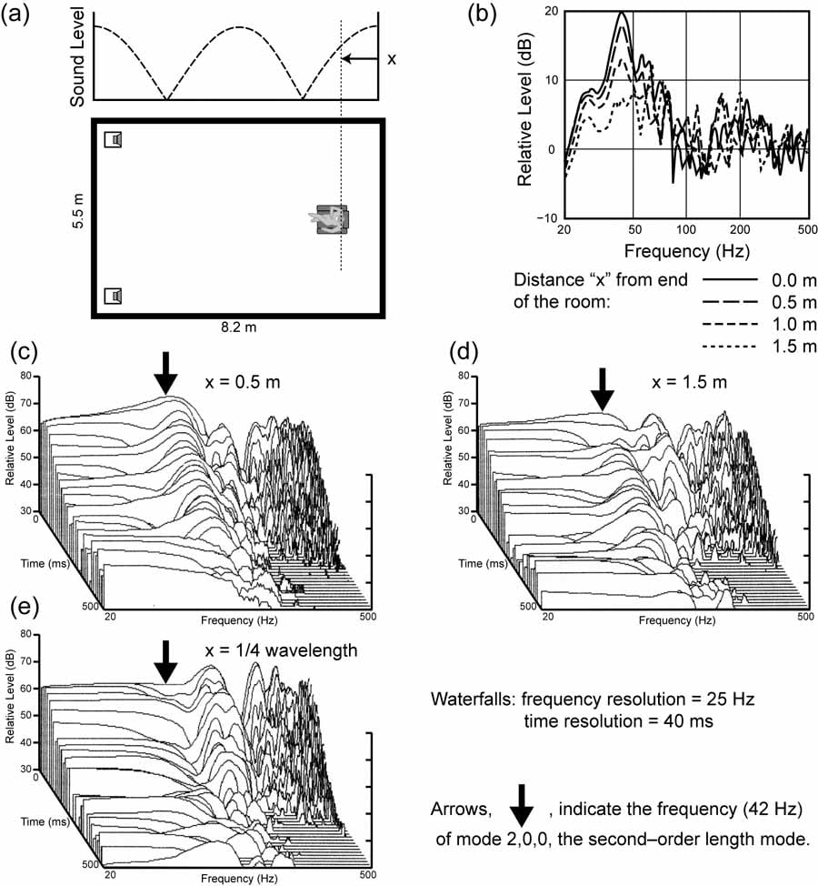
Figure 13.20 Frequency and Waterfall Plots of Living/Listening Room
This was a totally passive solution - no modifications except that my chair ended up in a silly location 5 feet out from the back wall. I put up with this for a while, but when I started to see tracks in the carpet from dragging the chair out for my listening sessions I decided that a better solution was needed. Attentive readers will have noted that I could have moved the loudspeakers instead of myself, but in that situation it was simply not an option.
So, I put the chair back where it logically belonged, inserted a parametric equalizer into the system, matched the center frequency and Q of the resonance and turned it down. When it sounded right, the measured steady-state room curve looked a lot like the one with the chair moved, and the bass boom was similarly gone. In numerous A vs. B comparisons I did with my audiophile friends it was impressive how similar the two solutions sounded. Everybody was surprised how a kick drum went from a flabby “boom” to a tight “slam” at the flick of an equalizer switch. I show these measurements in Figure 13.21 in my book, and below. Room resonances at low frequencies behave as minimum-phase systems and properly matched parametric EQ can repair both the amplitude and time domain problems. Off-the-shelf automated "room EQ" or "room correction" programs may or may not be able to do this properly. Many do not.
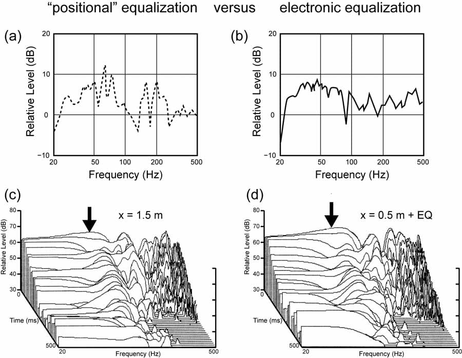
Figure 13.21 Positional vs Electronic EQ
But was the mode eliminated? Yes, but only when the sound system was running and only for the sounds radiated by it. It is the same as in the mode canceling system, but this time it was most effective for the prime listening location and a seat on either side of me. Other locations in the room took their chances. But, for me, a mostly solitary listener, it was a totally effective solution, and it was totally invisible. In truth, because the signal delivered to the woofer was attenuated by 14 dB, it worked much less hard, less amplifier power was used, and the system could be played louder while sounding much better.
Applying the Scientific Method to Audio
As history has it, in 1991 I moved from the National Research Council and our Canadian home, to southern California to join Harman International as Corporate Vice President of Engineering. We hated to leave the beautiful house and property, but . . . new opportunities beckoned.
In addition to my mainstream duties with the many companies under the corporate umbrella, I set up a small research group, aimed at pushing the envelope of knowledge - there was no product development, but only ideas that might benefit products. Papers were to be published, the information shared, not kept as corporate “knowhow”, unlike several other corporations. Thank you Harman! I am now retired, but under the guidance of Dr. Sean Olive, the group continues to ask and answer questions using the scientific method.
I never forgot the neat acoustical solutions just described, but in thinking about it further I reckoned that in small rooms there are only a small number of modes in the subwoofer frequency range - maybe there could be a more generalized solution that could benefit multiple listeners. After I hired Todd Welti we had the means to explore this using his expertise with Matlab. It was not long before he had the first multi-sub solutions (AES preprint 5602 (2002). After exploring what was possible with up to 5000 subs (aka. acoustic wallpaper) it was found that in practice no more than four subs were needed, and two could do a reasonable job - but only in simple rectangular rooms and only for seats in the middle of the room. Figure 13.17 shows some results. This is not what many people think: more subs "filling in" holes or scrambling the sound field. It is pure room mode manipulation, discouraging some modes and encouraging others. By reducing the number of active modes in the room to the second-order length, width and tangential modes, the nulls are all at the 25% distance from the walls (dashed lines in the illustration), and there are some areas that are relatively free from these problems. The subs must be identical, driven with the identical bass-managed signal, and in specific locations. Three of the most effective and efficient arrangements are shown. In general the four-corners solution tends to be preferred. Other arrangements work, but all are less efficient – see my book or the Welti paper. The best listening locations are in the center area of the room, but because few rooms are perfectly symmetrical from a wall construction perspective, including doors, windows, fireplaces, etc., there will be variations. On site measurements and equalization are recommended but the situation has been greatly simplified.
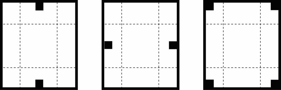
Figure 13.17 Rectangular Room Sub Layout Options
For a more detailed analysis of multi-sub location options, see: Optimum Room Locations for Subwoofers
How to Interpret Waterfall Graphs
I have seen some number of those photogenic waterfall diagrams lately. Figure 13.23 in my book, shown below, shows several ways of portraying exactly the same room. In waterfall diagrams there is a trade-off. You can have high resolution in the frequency domain, or high resolution in the time domain, but not both. This gets forgotten, or is not known by those making the measurements, or - cynically - is used to mislead.
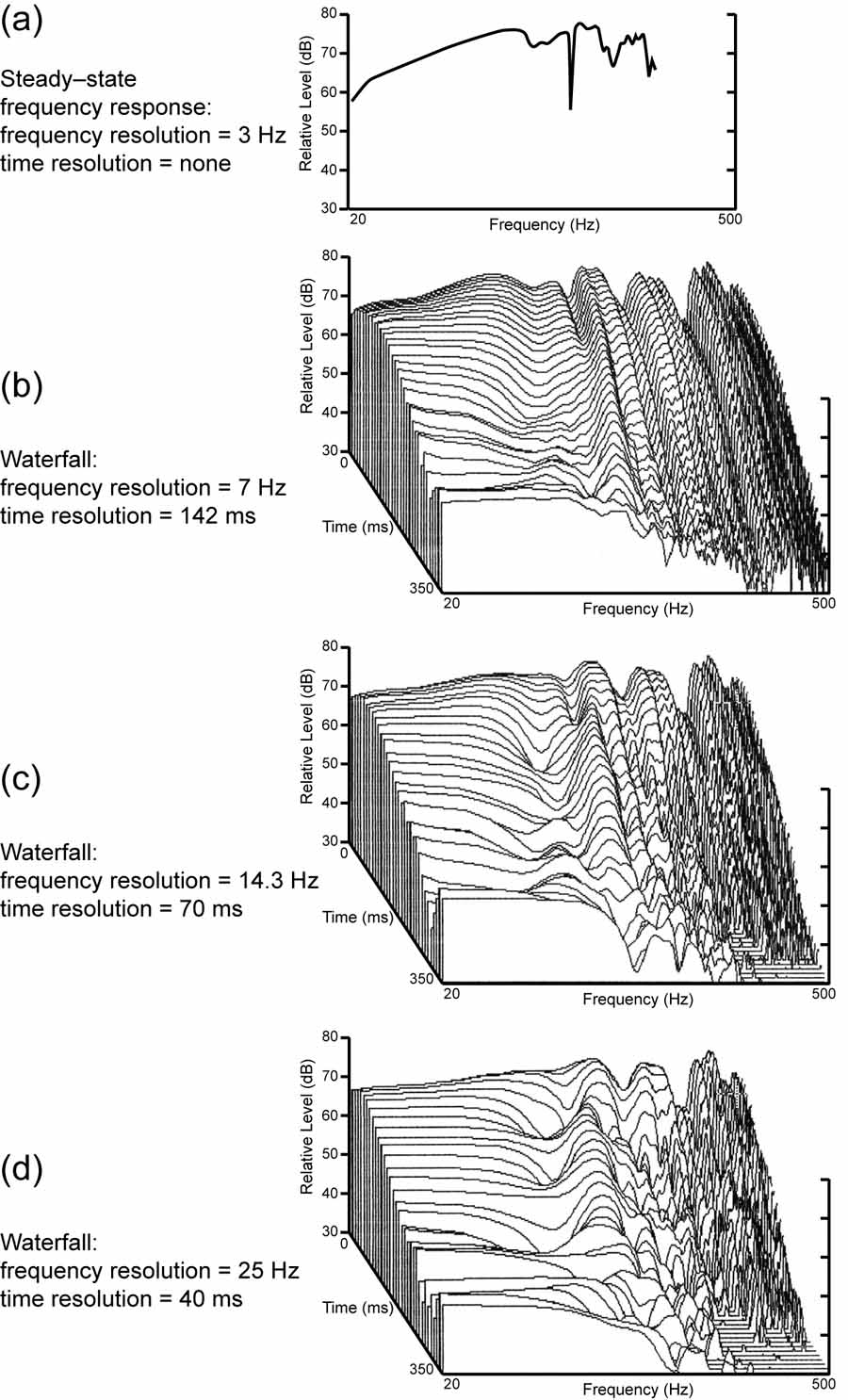
Figure 13.23 Waterfall Graph Comparison
The top curve is a high-resolution steady-state frequency response, reasonably smooth, a good result for an unequalized room. This is from my first exercise in mode cancelling, shown earlier. The cancellation notch is present.
The first waterfall (b) shows a room that appears to be out of control, with numerous "resonances" ringing forever. This is the one with high resolution in the frequency domain, showing lots of detail, but as you move forward from time=0 the curves change only very slightly, maintaining their shape out to 350 ms. This looks alarming. But every curve moving forward is an average of events over 142 ms, so rapid change is impossible to see even if it is there. We are not seeing what is happening in the time domain.
The next waterfall in (c) has less resolution in the frequency domain, but more in the time domain, and now we see that the events in the time domain are more interesting, changing. In (d) with even less frequency resolution we see that moving forward from t=0 the curves start changing immediately, quickly taking on very different shapes. It is clear that there is only one resonance of any consequence and it is about 10 dB below the initial sound level, i.e. not likely to be a problem. All that was done here was to change the settings on the analyzer. It is the same room. Yet we have seen what could be portrayed as an uncontrollably boomy room, through to one that is very well controlled. Fortunately, that is the message conveyed by the steady state room curve, and that is precisely how it sounded - good.
Waterfalls can be useful, but many I see are just ornaments. Because of the ambiguity in what they show, they convey little or no information that cannot be inferred from a simple frequency response curve. But they are pretty.
The last illustration, Figure 13.24 in my book, shows things very clearly in a frequency response and a time response. It is clear that a properly matched parametric filter (a) is superior to an unmatched one (b). So, all equalization is not equal, but when properly done, it works in both the frequency and time domains. These data came from a hands-on measurement/equalization training session at a CEDIA event, and all present had no difficulty hearing the differences that are displayed here. In (b) the nice looking “after equalization” data described a system that was audibly inferior to the one in (a). Science works.
In a normal loudspeaker/room system these results can only be expected at the measurement location. However, with multiple subwoofer schemes that yield similar frequency responses at several seats, global equalization can then benefit all of those listeners.
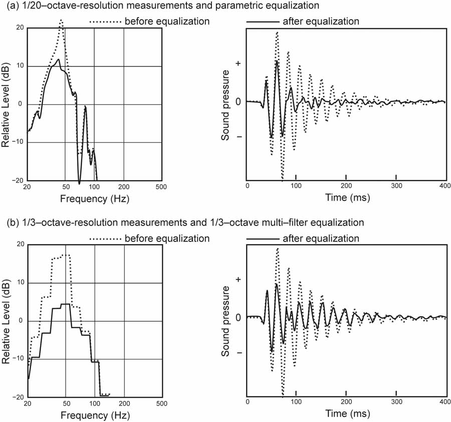
Figure 13.24 EQ and Ringing
The Birth of Sound Field Management
But simple rectangular rooms are not everywhere. We needed more flexibility, and besides, my new listening room was not a simple rectangle, and again I was not enthusiastic about filling it with bass traps. This was another case of (personal) necessity mothering an invention. My talented employees Todd Welti and Allan Devantier went to work, and came up with something we call Sound Field Management (SFM). (Welti and Devantier, J. Audio Eng. Soc., vol. 54, 2006). This is much more complicated, involving transfer-function measurements from each subwoofer location to each specified seating location. An optimization algorithm then chews away at the data and comes up with specifications for the signal processing necessary for the signals being delivered to each of the (usually) four subs. Amplitude, delay and one parametric filter will be specified. The goal is to minimize the bass variations among the specified seats so that equalization, if it is necessary, will be equally effective for all listeners. It works superbly. My room is shown in Figure 13.18 and another in Figure 13.19. There are no bass booms. Kick drums are "tight", and it works for all five seats, some of which are in “unconventional” locations – it is a media/family room, not a dedicated theater, but with a 10 ft screen and seven identical loudspeakers it is mighty good. Below is a summary illustration emphasizing the fact that although less power is delivered by the subwoofers, an average of about 10 dB higher sound level is achieved in the room. Some of the subs are loafing, and could be reduced in size and power. Remember, in any normal situation turning up the volume by 10 dB uses 10-times more power. The subs can be flexibly located, although there are preferred locations, and they need not be identical. This is truly room mode control, removing destructive cancellations and liberating more good bass for more listeners. There is no global equalization in the curves shown.
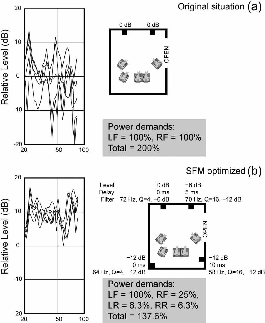
Figure 13.18 Multi-Seat Measurements with SFM Optimization
Again, were the room modes eliminated? Yes, but only when the audio system is running, and only for the sounds radiated by it. Now, though, it has been done for several seats, and in practice one finds that the bass is comparably good in the intervening spaces - put on a loop of kick drum and bass guitar and walk around the room. The bass response is tight and very consistent, and the normal sense of a "room" has disappeared. It is not inexpensive, and it is not universally available (pity), but it is a very effective and visually unobtrusive solution.
Editorial Note about Sound Field Management (SFM)
SFM is NOT simple EQ or room correction. I apologize if my article lead you to that conclusion. SFM, or Sound Field Management, is indeed a reference to a very specific Harman proprietary system to reduce seat-to-seat variations. Part of it is the usage of multiple subs. Todd Welti and Dr. Sean Olive's team developed an algorithm that further reduces seat-to-seat variation, which is part of their PC-based “ARCOS” characterization, EQ and processing solution. During the characterization phase, each subwoofer is measured independently at each seat. Then an optimization program determines the signal processing for each one independently only for the purpose of minimizing seat-to-seat variations when they all are running simultaneously. Only after that is completed does the system calculate the coefficients for global EQ, which is really only possible once one has reduced the seat-to-seat variations in response. Harman actually has a patent on it and their tech papers and patent prove that it does fix seat to seat consistency. Again it actually measures delay, phase, level, slopes, etc and computes best possible settings for each sub to get them to integrate optimally across all seats. Once you do that, then you can apply Global EQ to flatten bumps.
Would bass traps have delivered a similarly good result? Of course they would have have yielded a greatly improved bass response. It would just have been a very different looking room. If the physical volume and visual aesthetics of bass traps are not a problem, they work. It is straightforward physics with decades of experience behind it. If you are building a studio or performance space, they are the only solution. But for sound reproducing rooms, now we have some alternatives. Low-frequency absorption is always a good thing, and if you can find ways to incorporate it, do so. It will make whatever else you do work even better.
Conclusion
 Whatever solution(s) you choose, it is likely that some bass equalization will
improve things. Just don't automatically extend the equalization above a few
hundred Hz, because that is where the loudspeaker itself takes over and if you
have good loudspeakers you might risk making them worse.
Whatever solution(s) you choose, it is likely that some bass equalization will
improve things. Just don't automatically extend the equalization above a few
hundred Hz, because that is where the loudspeaker itself takes over and if you
have good loudspeakers you might risk making them worse.
Make your choices, it is a free world.
Summing up, there are several means at our disposal to improve bass in small rooms. Depending on your taste, budget and physical circumstances, any one or combination of these options may help. Low-frequency absorption is always beneficial, and enough of it may be all that is necessary. However, not every situation is compatible with the visual and physical compromises. In those cases, technology may be able to provide satisfaction.
I am pleased to have been a contributor to these optional solutions – motivated by pure, selfish, necessity :)