
Revamping a Vintage Yamaha T-80 Tuner
Recently I acquired a Yamaha T-80 tuner. This tuner was manufactured in the mid 1980’s, probably in 1985 from what I can tell. I proceeded to put the unit in my system and connected it to a standard FM dipole antenna. My initial impression was that this had some potential, but was going to need a lot of work. This appeared not to be your usual consumer toy tuner.
I did a bit of web searching on FM tuners and found one particular web site that had a fair amount of information: www.fmtunerinfo.com The general consensus seemed that in the mid 1980’s a number of Japanese and American manufacturers made some very good consumer issue FM tuners. The general consensus also to be that after the 1980’s most of these companies decided not to pursue this much further. This may well be due to the decline in this section of the market.
I then proceeded to contact the Yamaha service department for the service manual. Yamaha did not have extra manuals for sale but they did send a Xerox copy of the one they had in the service department at no charge. Thank you Yamaha!!! It’s not often that one can find a service department this helpful and cooperative.
After looking over the schematics I was pretty impressed by some of the techniques that they were using in the RF section and made the decision to bring this unit back to original condition and better. I took some initial data on the +/- 12volt supply lines right at pin 4 and pin 8 of the output op amp. The data was not exactly what I would call acceptable.
One of the biggest problems that aging units have are the electrolytic capacitors. A generally accepted life span for an electrolytic capacitor is approximately 15 years for consumer applications. There is plenty of variation here as heat will accelerate the aging process. One of the more pronounced effects of electrolytic capacitor aging is that they start to behave more like resistors rather than capacitors, and when they do finally fail they generally take a bunch of circuitry with them! Considering that this is a twenty year old unit with hard to find, if not impossible to find parts, the first step will be to replace ALL of the electrolytic capacitors. This may appear to be excessive for some folks, but good quality, high temp (Sprauge 517D series:105 C) electrolytic capacitors are not exactly expensive. My replacement cost was about forty dollars, including shipping, for the entire unit.
Replacing all of the electrolytic capacitors is not exactly what I call exciting or glamorous; in fact it’s downright boring. I do have some general desoldering tips for the DIY folks. When you are desoldering a component from the PC board, use a drop or two of flux on the area that needs to be desoldered. The flux will help the solder flow quickly and easily, speeding up your work, which will give you less chance of destroying a pad or etch. Cleaning up can easily be done with an acid brush and 91% Isopropyl Alcohol available from your local drugstore.
After all the electrolytic capacitors were replaced I did add some 0.1uf film bypass caps in the power supply and added some 0.01uf ceramic bypass caps in the RF section. To do this; simply solder the bypass caps directly across the electrolytic capacitors. Most consumer units of this era did NOT have these in their units to start with. Once this was completed I went back to my original supply pins on the output op amp and found a 9 db reduction in ripple and approximately 18 db reduction in broadband noise.
A few words of caution to the DIY folks on electrolytic capacitor replacement: The first instinct is to increase the capacitance for better filtering. The problem with this is that surrounding design may NOT be able to handle the surge currents of larger capacitors and cause premature failure of rectifier diodes, pass transistors, and force a transformer into saturation. I would also like to note that on the + 12 volt rail I found the ripple was down to 1 mV p-p and the –12 volt rail was less than that after doing the electrolytic capacitor replacement.
My next step is to replace a good portion of the carbon film resistors in the unit. The carbon film resistor is typically the dominant source of thermal noise in audio circuits. Metal film resistors have much lower thermal noise. I proceeded to replace all of the carbon film resistors in the audio output circuit, multiplex circuit, IF filter section, and the bias resistors for the pass transistors in the power supply. To ensure accuracy I measured each resistor just to be sure I was reading the color code correctly and replaced each resistor with the equivalent value metal film resistor. The reduction of thermal noise is very audible to most folks and as the spec’s will show a real difference in the S/N ratio. In addition I replaced the JRC 2041 dual op amp with an OP275. An OPA2134 will work just fine in this application too.
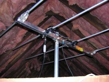
Now that I have completed the basic restoration and noise reduction of the T-80 tuner it’s time to start on setting up a decent antenna. An outdoor rotating antenna would be the optimum choice here, but my present living circumstances are not going to allow that. I am not a DX guy as my major goal is to get decent reception from the many Boston area radio stations. A friend of mine who had come to visit recommended using the attic, which has enough space to put in a 4 element Yagi. I presently live about 15 miles up the coast from Boston so mounting a small Yagi from Winegard (Pro 6000), http://www.winegard.com/offair/pdf/pr-6000.pdf seemed like an acceptable alternative to the standard FM dipole. I spent a few evenings on antenna placement and found the following. Just about anywhere in the attic with antenna pointed toward Boston gave me about the same results. Even with an extra 37 feet of RG 6 added I found no real difference monitoring the signal quality meter and the multipath meter. I got the RG6 I am using at Home Depot. I also did a search through the Belden Master Catalog and found that RG6 typically has an insertion loss of 2.5db for every 100 ft. at 100 MHz. I am presently using about 32 ft. so that gives me just under 1db of loss from the antenna. The only spot where I had problems was near the chimney. The antenna itself was very inexpensive. The cost from Lashen Electronics in New Jersey was about 47.00, which included the mast and Balun to convert the 300 ohm antenna to 75 ohms. The antenna is extremely light so body building is not required for placement. The shipping cost came to about 35.00 due to UPS claiming it was an oversize package. UPS also managed to nearly destroy the cardboard packaging but the antenna itself was not damaged.
The final result confirms the age old RF truism: “There ain’t nothing like a good directional antenna to boost signal quality and reduce multipath.” Multipath distortion has that real grinding quality to it that all of us could do without. Lowering multipath should be of primary concern when placing an antenna. Fortunately the Yamaha T-80 has a multipath meter to monitor this when you placing the antenna.
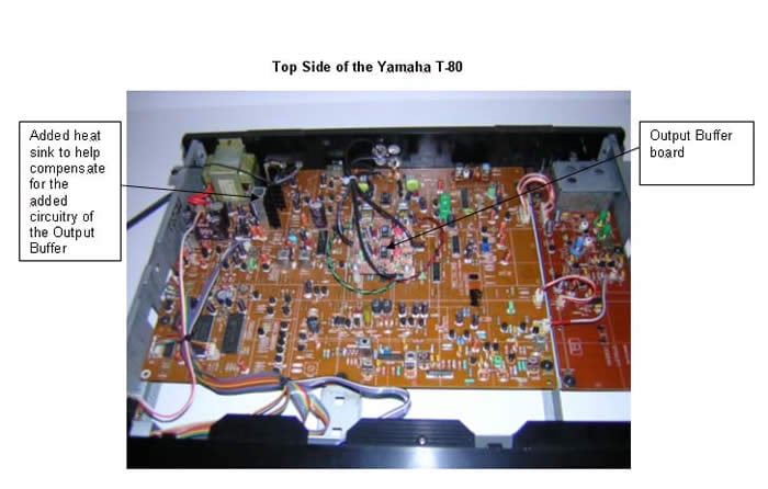
T-80 Board Layout
Most FM tuners from this era suffer from two major problems. They have a high and reactive output impedance, and the grounding scheme inside the unit is at best dubious. This is a unit from the era when single sided boards where standard issue. The near total lack of ground plane and high impedance returns to the power supply are very much part of this unit. One wonders what the performance might have been had Yamaha decided to use a double sided board with a fair amount of ground plane on the component side of the board. The following will show an approach to tackle both of these problems.
The following schematic is of the T-80 output circuit and the buffer installed to lower the output impedance so I can drive a Jensen Audio Isolator, which is just a pair of Jensen line level transformers in a package.
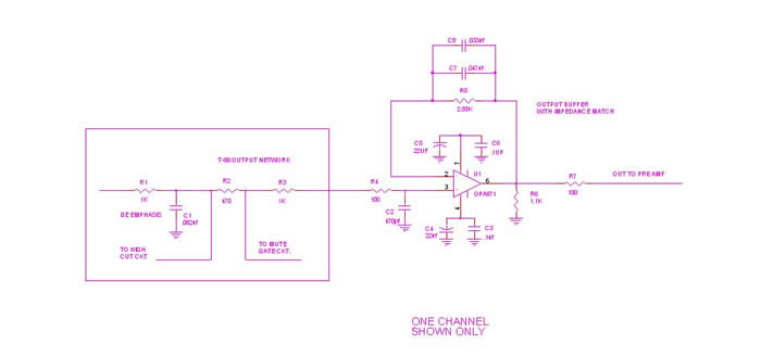
Please note the feedback network from pin 2 to pin 6 of the op amp. The 2.55k ohm resistor is the approximate resistance match of T-80 output circuit and the two capacitors in parallel represent the capacitance match of the T-80 output circuit. Although it is not shown here, when the T-80 has the high cut filter added the capacitance will double. The high cut circuit is only activated when you find a very noisy station that is not coming in well in local mode. For my present antenna configuration I really don’t need this and the output circuit is “optimized” for local stereo mode. This circuit will reduce upper order distortion, especially when connected to a relatively low impedance input and lower the output impedance to 100 ohms to drive the Jensen Audio Isolator. For technical information on the Jensen Audio Isolator Go Here: http://www.jensentransformers.com/datashts/ci2rr.pdf
And for a good price on this unit try here:
Jenson CI-2RR RCA Audio Hum Eliminator
At time of writing the CI-2RR is available from www.markertek.com for 119.00
Although transformers certainly have some drawbacks, they are very effective in isolating the ground of one unit from another. Given the grounding scheme used in the T-80, the use of the transformers has been very effective in reducing noise. They are not cheap, but many of us find the performance well worth it.
When I received the tuner back from alignment at Stereo Surgeons in East Hartford CT. http://www.stereosurgeons.com/ I noted many performance changes. Sensitivity, stereo separation, and distortion had definitely improved, but with the increase in sensitivity noise had also increased. I went back to the schematics for further study, and also had a good long look at the board layout. I noted that all the 0.01uf and 0.022uf bypass caps in the RF and IF sections were ceramic disc caps, and after looking through some data sheets on class three ceramic disc caps I noted that aging characteristics on class three ceramic caps was somewhat similar to electrolytic caps. I decided to replace them with NPO ceramic caps. This may well be excessive for this application and in all probability the CKO5 series caps would do just fine. So I will plead “mea culpa” to being a certifiably excessive here. I also added 0.1uf bypass caps across the electrolytic capacitors in both the RF and IF sections.
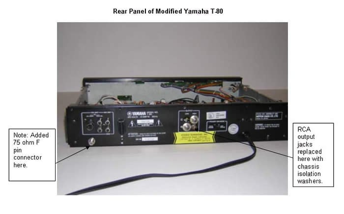
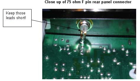
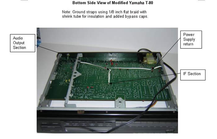
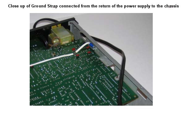
As I previously noted in this article the board layout is single sided and ground plane in the unit has been sacrificed to accommodate a single sided board. The main ground to the chassis appears to be a chassis support bracket that goes down between the RF section & the rest of the unit. I added ground straps using 1/8 inch flat braid from the return of the power supply to the chassis. From the return of the power supply I added a ground strap that went to small ground plane near the audio output. From there a ground strap was connected to a small ground plane of the IF section. From that same ground plane in the audio output section I added another ground strap to ground plane next to the bracket. The very last thing was to install a 75 ohm F pin connector for the RG6 cable run from the antenna. When the Yamaha T-80 was produced Yamaha used their own custom 75 ohm connector and these parts are no longer available. Note from the photo the short lead length down to the P.C. Board.
The decrease in noise was very audible from the above “modifications”, and now needs to go back for measurement to verify this, but it is right here that I ran into a brick wall. After e mailing a number of people recommended at www.fmtunerinfo.comI found the following: The shops that still do FM tuner alignment have found it cost prohibitive to keep their equipment up to original factory specifications and also find that there is little demand for this from the public, especially when it comes to accurate measurements of noise in this application. While I certainly understand from a business standpoint I am still saddened by this state of affairs. I would like to apologize to the readers of Audioholics, but please keep in mind that Gene and I appear to have exhausted all possibilities. If this changes, we will gladly update this article.
Well; what’s the final verdict here? And, just how good is FM radio in the Boston area as viable music source? The first thing I need to tell you is that there is no shortage of variables here. FM pop music stations that add their own compression on top of the compression already on the CD will not be discussed further. My observation is that some stations appear to care about the quality of their transmission, and have the budget to do so. National Public Radio in particular and the local college stations are O.K., but they really don’t have the budget they would probably like to have. Playback can vary from records to CD’s, but I will tell you this: with this tuner and antenna set up, when NPR decides to spin a well recorded CD, the playback through this tuner comes very close to a top notch reel to reel tape player in near perfect working order. I’ve even surprised a few folks into thinking that they were listening to a CD., and the level of performance that is possible has raised my eyebrows from time to time. This maybe hard to believe folks but FM radio here in Boston is better than I ever expected and I have been well rewarded for the time and money spent. If you can find some money in your charity budget give to National Public Radio and your local college stations, and you have a decent tuner, your ears will be well rewarded.
T-80 Modifications
Winegard Pro 6000 Antenna
T-80 Measuments and Analysis
Yamaha T-80 Tuner Tests
These tests were done on a modified tuner supplied to me for testing by Dan Banquer. The test equipment used was as follows:
FM Stereo Test Generator – Panasonic VP-8122A
FFT Analyzer – Ono Sokki CF-6400 (16 bit A/D resolution, 100kHz max. Bandwidth)
HP 100MHz Scope
After receiving the tuner, it was allowed to warm up for about 2 hours, then given a complete alignment per the T-80 factory manual. Then, the following tests were done using the FFT analyzer for measuring distortion, separation, and frequency response.
The instrument settings were as follows:
RF level – 65dBf
Generator mode – Stereo, 1kHz test signal, L or R output, 100% FM Modulation, Pilot 10%, frequency 97.9 MHz
FFT – 800 lines resolution, flat top window, 25 averages
The first two plots below show the 20 kHz response to a 100% modulation signal in the left channel, then right channel, in wide IF mode. This plot shows the harmonics, the averaged noise floor, and 19 kHz pilot leakage.
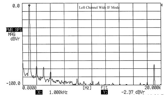
Figure 1 – 1kHz, 100% FM modulation, left channel, wide IF mode.
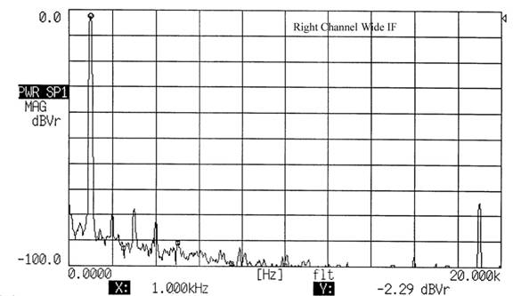
Figure 2 – 1kHz, 100% FM modulation, right channel, wide IF mode.
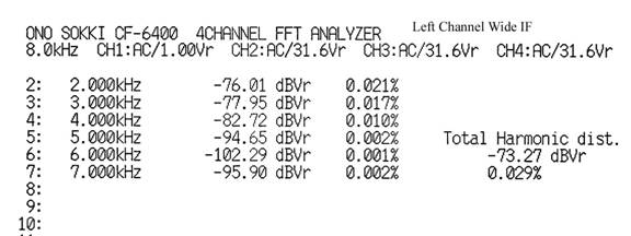
Figure 3 – Harmonic Distortion table from 8 kHz BW FFT spectrum, left channel, wide IF mode, 0.029%.
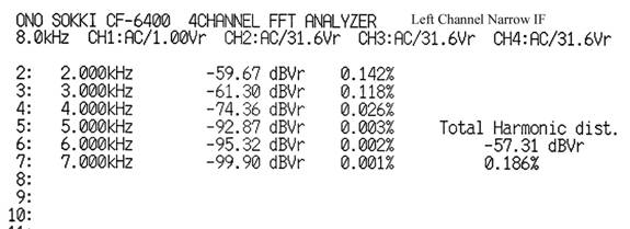
Figure 4 – Harmonic Distortion table from 8 kHz BW FFT spectrum, left channel, narrow IF mode, 0.186%.
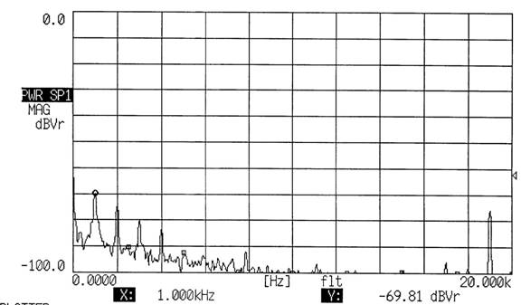
Figure 5 – Separation in Right channel, wide IF mode, 67 dB.
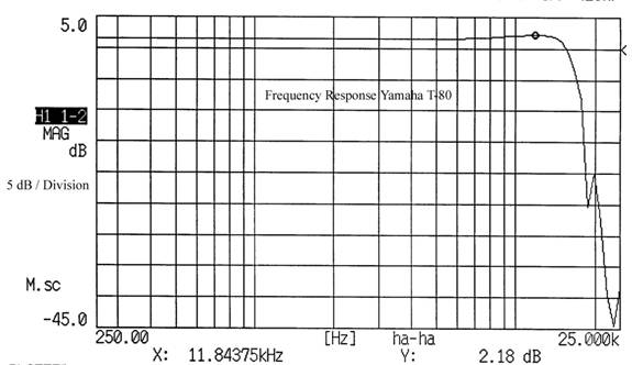
Figure 6 – Frequency Response from 250Hz to 25kHz. Response was plus 0.4dB at 12kHz, minus 3dB at 17kHz, -25dB at 19kHz.
Dan asked me to look specifically at the noise floor of his modified tuner, as he had made improvements in the ground scheme, as well as replaced many components like resistors with low noise types. Figure 7 shows the comparison of my stock freshly aligned T-80 versus Dan’s modified unit. The measurement was made in stereo, very similar to the way separation in figure 5 is measured – the 100% modulation 1kHz signal was applied to one channel, while the measurement was taken on the opposite channel (25 power spectra averages). As shown in figure 5 above, the remaining other channel signal (you don’t have infinite separation), pilot, distortion, etc. (plus noise floor) remain in the plot. For definition, I’ll call everything except the flattish noise floor “spurs”. For figure 7 below, I ignored all of those mentioned “spurs”, and simply looked at the averaged noise floor from DC to 20kHz. The FFT analyzer input setting was adjusted to a lower input level, so these very low relative levels could be seen. As in the above plots, the normal 100% output level was –2.29 dBVr. Remember, these noise floor numbers correspond to 20,000/800 lines = 25 Hz wide bandwidth FFT bins, and cannot be directly compared to wideband signal to noise ratios commonly seen in spec sheets (those numbers should also include some, but not all of the above spurs). But they do have merit for direct comparison of one tuner against another.
Figure 7 - Noise Floor, Bob’s Stock T-80 vs. Dan’s modified T-80
Overall, in listening tests, Dan’s modified tuner easily surpassed the stock Yamaha T-80 in all areas, with a better weight and articulation in the bass, more articulation in the midrange, and a slightly cleaner presentation in the highs. As the above data shows, with strong input signals, the averaged noise floor is also clearly better, from 4-9 dB better depending on the frequency. In general, it was one of the best sounding tuners that I have the pleasure of listening to in my system.
Many thanks to Bob Fitzgerald from www.fmtunerinfo.com