
Balanced vs. Unbalanced Cables
In discussing the characteristics and performance of various interconnect systems; two points should be kept in mind.
Balance is defined in terms of the impedance of the two signal conductors with respect to a reference, which is usually ground. If these impedances are equal and non-zero, the system is balanced. If the impedances are unequal the system is unbalanced. A signal conductor with a grounded return conductor is, therefore, an unbalanced (sometimes referred to as a single ended) system.
A small, common-mode, 60 Hz noise, voltage can exist between the chassis of two AC powered devices regardless of whether they are safety grounded (use a three-wire plug) or not.
Unbalanced Interconnections
An unbalanced (single ended) interface uses only two conductors to carry the signal from one device to another, one conductor carries the signal and the other is the grounded return. In consumer audio systems this usually consists of a cable with a center conductor and a shield terminated in an RCA Phono plug.
RCA Phono Plug
The ubiquitous "RCA Phono" plug was developed by RCA over fifty years ago to be used for short interconnections between a turntable and amplifier inside a phonograph, hence its name. This unbalanced interconnect system is simple and inexpensive, but as with many other connector systems has been adopted for uses other than originally intended and has become the de-facto connector for consumer audio/video equipment. Note, however, that the design was original intended only for short cable runs within the same piece of equipment. Being an unbalanced system it is susceptible to common-mode noise voltages.
A problem occurs when there is a ground voltage (common-mode voltage) between the two interconnected devices. Because of this voltage, a small current will flow down the cable shield between the devices (often referred to as common-mode current, or as a ground loop current). If the cable shield were ideal (zero impedance) this current would not cause a problem. However, since the shield has a finite resistance, a small noise voltage will appear across the length of the cable shield. The magnitude of this voltage will equal the common-mode current times the shield resistance. This voltage is in series with the signal voltage and will add directly to it at the receiver. In other words, an unbalanced interconnect system consisting of only two conductors (center conductor plus a shield) has no ability to reject common-mode noise voltages.
This coupling is referred to as common-impedance coupling , and is the result of the fact that in an unbalanced two-wire system the shield is performing two functions. It is a shield carrying the common-mode noise current, but it is also one of the signal conductors carrying the return signal current.
For more details on common-impedance coupling see "Noise Reduction Techniques in Electronic Systems," Second Edition, page 54, by Henry W. Ott, published by Wiley-Interscience, 1988.
Example 1: Let's consider a typical case of the interface between two grounded (3-prong AC plug) pieces of audio equipment. Some actual cases will be better than this example and some will be worse. The shield resistance of a fifteen-foot cable might be about 0.25 ohms. If the 60-Hertz shield current is 250 uA, the voltage developed across the shield will be 62.5 uV. For consumer audio products the reference signal level is about 300 mV (-10 dBV). The signal to noise ratio will therefore be 74 dB. For a high quality consumer audio system we would probably like the S/N ratio to be greater than 100 dB. Therefore, we would most likely be able to hear some 60-Hertz hum in quiet passages of the program material.
You might conclude at this point that ungrounded equipment, those using a 2-prong AC plug, might solve this problem by eliminating the ground connections. This often helps, but does not necessarily eliminate the problem. For ungrounded equipment the common-mode ground current can still flow through the inter-winding capacitance of the power transformer. The impedance of the capacitor will normally reduce the magnitude of the current (typically less than 100 uA), and hence the noise voltage, but some noise will still exist. Since the impedance of the inter-winding capacitance is frequency dependent, more current will flow at high frequencies (harmonics of 60 Hz) than at the fundamental frequency (60 Hz). Therefore, the interference will more likely consist of a high frequency buzz instead of a 60 Hz hum.
Despite its shortcomings, this unbalanced system works surprisingly well most of the time. In particular, in cases with short cable runs, and with very little, or no, 60 Hz voltage between the chassis of the interconnected devices.
Unbalanced Interface Cables
From the above discussion, we can conclude that for the case of an unbalanced interface, the only property of the cable that has any significant effect on the common-impedance noise coupling is the shield resistance.
What can we do to minimize the possibility of problems when using this very common unbalanced interconnect system? First, we want to minimize the common-mode voltage difference between the interconnected devices. If possible, plug everything into the same AC power outlet, or power strip. If that is not possible plug the interconnected equipment into power outlets that are on the same branch circuit (same circuit breaker). Another possibility would be to run an additional heavy gauge (low resistance) ground wire between the chassis of the two devices to divert some of the common-mode cable shield current.
Second, we want to minimize the resistance of the interconnecting cable shields. Use cables with a copper braid (or even spiral copper) shield instead of a foil shield. Use cables with the heaviest shield possible, or with double shields in order to minimize cable shield resistance. Do not use cables with aluminum foil shields, since their resistances are much higher. (Note: A foil-braid combination shield is fine, as long as the low resistance copper braid is present). Also keep cables as short as possible, since this will also reduce the total shield resistance.
Thirdly, you can isolate or break the common-mode shield current path. Most people try to do this by removing or lifting grounds on the AC power cord. This can be very dangerous since it can lead to safety problems. The AC power cords and connections should be left alone, exactly as the manufacturer designed them. It is much better, and safer, to do the isolation on the interconnecting signal cables.
This can easily be done by using high quality signal isolation transformers designed specifically for this application, such as the ISO-MAX® line of transformers manufactured by Jensen Transformer Corporation (www.jensentransformers.com). An isolation transformer allows the signal to pass through while at the same time breaking the ground connection and thereby eliminating the common-mode current. These transformers are available for audio signals, video signals as well as RF signals. Although quality isolation transformers are expensive (MSRP of $50 to $100) they work extremely well and their cost is usually negligible compared to the overall cost of a high quality audio system installation. Low quality, inexpensive isolation transformers are also available, however, they will seriously degrade the quality (frequency response) of the audio, video, or RF system.
Troubleshooting Audio Noise Problems
An excellent reference for troubleshooting audio system noise problems is the ISO-MAX® Troubleshooting Guide by Bill Whitlock. Go to Jensen Transformers Website and download the pdf file for the "Jensen Transformer Troubleshooting Guide."
Another approach would have been for the manufacturer to design the product with a balanced interface.
Balanced vs. Unbalanced Cables - page 2
Balanced Interconnections
 In a balanced interconnect system both of the signal conductors have an equal, and non-zero, impedance to ground. Therefore, three conductors are required, signal+, signal-, and ground or shield.
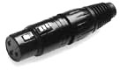
Professional audio installations often require long cable runs of 50 to 100 feet or more and have to be able to operate at microphone signal levels of 3 mV (-50 dBV) as opposed to a line level of 300 mV for consumer audio interconnections (a two order of magnitude smaller signal level). As a result most professional audio equipment is interconnected using a three-conductor balanced cable (two signal conductors and a shield) using XLR connectors, or in some cases 1/4-inch phone plugs.
1/4" Phone Plug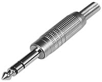 The 1/4" "phone" plug (not to be confused with the RCA "phono" plug) was developed by AT & T for use in early-day manual telephone switchboards, hence its name "phone plug." It can interconnect three conductors, referred to as tip, ring, and sleeve.
This three-conductor balanced interconnect system avoids the problem of the shield having to serve two purposes. The signal is now carried on the two internal conductors (usually twisted together) and the shield only acts as a shield and not also as a signal return conductor. The penalty for this improvement in performance is a more complicated and hence more expensive system.
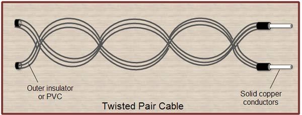
Advantages of Twisted Pair Wire
Twisted pair wiring, even when unshielded, is very effective in reducing magnetic field coupling to and from the wire pair. There are only two conditions necessary for this to be true. First, the signal must flow equally, and in opposite directions, on the two conductors. Secondly, the length of the twist must be less than one twentieth of a wavelength at the frequencies of concern. (One twist per inch will be effective up to about 500 MHz).
The above is true whether the terminations are balanced or not. In addition, if the terminations are balanced, twisted pair wiring will also be effective in reducing electric field coupling to and from the wire pair.
Even though field coupling is not the primary noise coupling mechanism in audio systems, it is still a good practice to always twist the signal and return conductors in a cable. (Twisting is especially important in the case of very low-level microphone cables.)
A 60 Hz shield current flowing between two interconnected devices will still produces a voltage drop in the shield, but this noise voltage is not in series with the signal. Rather it will be coupled equally (as a common-mode noise voltage) into both signal conductors. Since the receiver looks at the difference between the two signal conductors (not the voltage between one of them and ground), the common-mode noise voltage cancels out and is not seen by the receiver.
A balanced interface theoretically would be completely immune to noise and interference. In practice, however, nothing is perfect. Even if we attempt to make the impedance of the two signal conductors to ground the same there will be some difference, if only a fraction of a percent, and this will limit the degree of common-mode voltage rejection and hence the maximum noise suppression possible.
Example 2: Let's assume that the impedance balance is such that the circuit can provide 60 dB of common-mode noise rejection (an easily obtainable number) and that the other parameters are the same as in the previous example. (Note: a very well designed balanced interface can have as much as 80 to 100 dB of common-mode noise rejection.)
Since the shield resistance of a fifteen-foot cable is about 0.25 ohms and assuming the shield current is 250 uA, the voltage developed across the shield will be 62.5 uV (the same as in Example 1). This noise voltage is, however, not in series with the signal, rather it will couple as a common-mode noise voltage into the balanced circuit. Since (in our example) the balanced circuit has 60 dB of common-mode noise rejection, the noise voltage coupled into the receiver will be reduced by an additional 60 dB. Sixty dB represents a reduction of 1,000 to 1. Therefore the noise voltage coupled into the system will be only 0.063 uV (62.5 uV / 1,000). For the line level signal (300 mV) of Example 1, this represents a S/N ratio of 134 dB. We now have a very good quality audio system with the S/N ratio well above the desired 100 dB. Even for the case of a microphone level signal (3 mV) the S/N ratio is 114 dB, still a quite respectable number.
Balanced Systems
Note: In order for a balanced system to be effective in reducing common-mode noise not only must the interconnection cable be balanced, but the terminations must also be balanced. Using transformers or balanced amplifiers are two possible approaches to providing balanced terminations. A full discussion of the various ways to balance the terminations (and the advantages and disadvantages of each) is beyond the scope of this discussion.
Notice what has happened. For the case of the 300 mV line level signal, the unbalanced shielded cable of the first example provided a S/N ratio of 74 dB, and the balanced signal conductors of the second example reduced that noise by an additional 60 dB giving us the sum of the two or 134 dB for the overall S/N ratio.
Therefore we can conclude that for the situation described above, regardless of the signal level the balanced interface will have 60 dB (or more, depending upon the degree of balance achieved) less noise than the unbalanced interface.
The Telephone System
An excellent example of the effectiveness of using a balanced system to reduce noise is the telephone system, where signal levels are typically the tens to hundredths of millivolts. Telephone cables often run for many miles parallel to high voltage (4,000 to 14,000 volts) AC power lines and you do not hear any 60 Hertz hum in the telephone. This is because the telephone system is a balanced system. On the rare occasions where you do hear some hum in the telephone it is because something has caused an unbalance to occur in the lines, and it will go away once the balance is restored.
Conclusions
When using unbalanced interconnections between audio equipment the primary noise-coupling mechanism is due to common-impedance coupling. The cable shield resistance is the common-impedance, and any small 60 Hz AC potential between the equipment chassis is the noise source producing a common-mode noise current on the cable shield (ground loop current).
This problem can be minimized, or eliminated, by any one of the following approaches:
- Minimize the AC voltage between the two pieces of equipment.
- Minimize the cable shield resistance.
- Block the common-mode noise current by using a signal isolation transformer.
- Use a balanced interconnection system.
Check Out Our Article on Ground Loops for more information
Electric and magnetic field coupling to the interconnection cables, although possible, is not normally a major noise problem in most audio systems.
Special thanks to Henry Ott Consultants: http://www.hottconsultants.com
For more details on the characteristics of balanced systems see "Noise Reduction Techniques in Electronic Systems," Second Edition, Chapter 4, Balancing and Filtering, by Henry W. Ott, published by Wiley-Interscience, 1988