
Velodyne Digital Drive Plus 18 (DD18+) Subwoofer Review
- Product Name: Digital Drive Plus 18 (DD-18+) Subwoofer
- Manufacturer: Velodyne Acoustics
- Performance Rating:

- Value Rating:

- Review Date: December 18, 2011 08:00
- MSRP: $ 4999
- 18” forward firing long throw woofer with active servo control
- Sealed 1” HDF contoured, window braced enclosure
- Amplifier: 1250 watts rms, 3000 watts dynamic power
- Frequency Response: 14.4-120Hz +/-3dB (8.8-300Hz Overall)
- Finishes: Black gloss ebony, satin cherry, walnut
- Dimensions (H/W/D): 22.7” x 20.7” x 25.6”
- Weight: 142 lbs.
- Warranty: 3 years electronics (5 years driver)
Driver features
- Rubber surround
- Fiberglass / Rohacell laminate cone
- Die-cast aluminum frame
- 39.7lb magnet structure
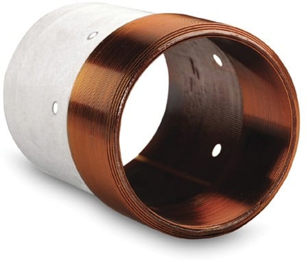
- 3” diameter 6 layer voice coil
- Vented pole piece
Additional Features
- Remote control
- On board DSP software based control system with measurement microphone
- Built in parametric equalization (8 bands) with auto or manual setting
- 6 user configurable pre-sets: Setup, theater, rock, jazz, custom, games
- Variable low pass filter, 40-199Hz in 1Hz increments and selectable 6,12,18,24,30,36db octave slope (Defeatable)
- Phase: Variable from 0 to 180 degrees in 15 degree steps
- Polarity switch +/-
- Selectable power mode: On, Auto-On, Standby
- THD% <0.5 typically
- Line and speaker level gain control (Send)
Inputs/Outputs
- Unbalanced (RCA) LFE input and output
- Stereo unbalanced (RCA) inputs and outputs L/R
- XLR balanced inputs L/R
- XLR balanced outputs L/R through
- XLR balanced outputs L/R high passed (6dB octave 80 or 100Hz)
- Speaker level inputs L/R
- Microphone input (Balanced mini XLR)
- RS-232 input and output
- 1/8” 12V trigger
- 1/8” external remote
- Ethernet port
- S-video jack
Pros
- Good looking
- Top notch parts and construction quality
- Feature laden: DSP, presets, remote, EQ, measurement system, accessory pack, etc.
- Great all around performance
Cons
- Very expensive
- Heavy
- Set-up options can be overwhelming
Velodyne Digital Drive Plus 18 (DD18+) Subwoofer Introduction
Velodyne has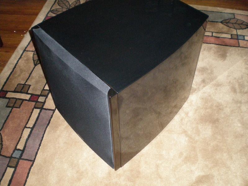 a long
and storied history in the commercial subwoofer market and after more than 25
years has solidified itself as one of the most recognizable names in high end
audio with their inovative technological advancements and commitment to pure
sound reproduction. The subject of this review is their top model in the
Digital Drive Plus line the DD18+ which
packs an 18” driver, a 1250 watt rated amplifier and a large amount of DSP and electronics
control. This unit represents the continued refinement of Velodyne’s top
subwoofer platform and follows the familiar Velodyne formula for success:
Active servo control, sealed enclosure, well engineered driver, powerful
amplifier and flexible built in DSP processing housed in a reasonably sized and
attractive package.
a long
and storied history in the commercial subwoofer market and after more than 25
years has solidified itself as one of the most recognizable names in high end
audio with their inovative technological advancements and commitment to pure
sound reproduction. The subject of this review is their top model in the
Digital Drive Plus line the DD18+ which
packs an 18” driver, a 1250 watt rated amplifier and a large amount of DSP and electronics
control. This unit represents the continued refinement of Velodyne’s top
subwoofer platform and follows the familiar Velodyne formula for success:
Active servo control, sealed enclosure, well engineered driver, powerful
amplifier and flexible built in DSP processing housed in a reasonably sized and
attractive package.
Unpacking and Initial Thoughts
The DD18+ is delivered by freight in a very large box and tips the scales at over 160lbs as delivered so it is a two person affair for most. Still unpacking was fairly easy and uninvolved. The DD18+ is double boxed and additionally has cardboard corner reinforcements. Inside of the inner box is a large top and bottom foam insert that fits over the DD18+ and houses the accessory pack. The DD18+ is also contained within a large cloth bag which is additionally inside of a large plastic bag with a small silica pack to combat moisture. Inside of the accessory box is: the measurement microphone in its own plastic snap case, the user manual, remote control, 2 discs containing the software to connect your TV or computer to the DD18+ and the audio track for measuring the response, a variety of cables for connecting the microphone, computer, television, etc and a pair of white gloves.
Note to Velodyne. Please include 2 pairs of gloves! How many new owners will move and position $4,999, 140lb subwoofers solo? Without a second pair of gloves the person gracious enough to help move the sub will be white glove-less, thus polluting the fine exterior of their shiny new subwoofer with their dirty mitts. That defeats the purpose of having the white gloves in the first place.
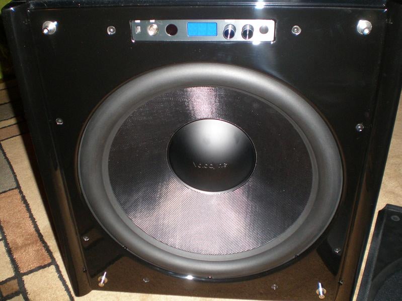
Initial thoughts after getting the DD18+ unpacked and looking through the accessory pack contents for a few moments? This is a very high quality unit here, man that is a nice finish and finally…Where to begin? The DD18+ came in the black gloss ebony finish that was really pleasing to my eyes. That particular finish is very dark and mirror polished, but you could still see wood grain underneath on close inspection. Everything about the DD18+ was constructed well, solid feeling and the curved side panels give it a streamlined appearance. The DD18+ is a good sized subwoofer that is not going to disappear easily, but it does have a very classy and high tech look to it. It reminded me of something that you would see at Bruce Wayne’s place.
Design Overview
The Velodyne DD18+ design utilizes an 18” driver in a sealed enclosure with a 1250 watt amplifier and includes a remote control for adjustment of output or EQ presets to suit your tastes without even having to leave your seat. This is already a recipe for quite the subwoofer, but the DD18+ doesn’t stop there and also utilizes Velodyne’s trademark active servo control which uses an accelerometer to monitor the voice coil position and provide adjustment to correct the output of the system and lower distortion. Velodyne claims this happens over 3000 times per second and the result is less than 1% THD during typical use. The DD18+ also houses a powerful DSP system which allows it to connect to a computer, measure and EQ its own response, or modify and save user presets for recall later. The DD18+ may also EQ itself with no need for connection to a display if there is none available to connect it to.
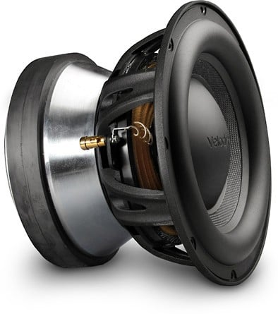
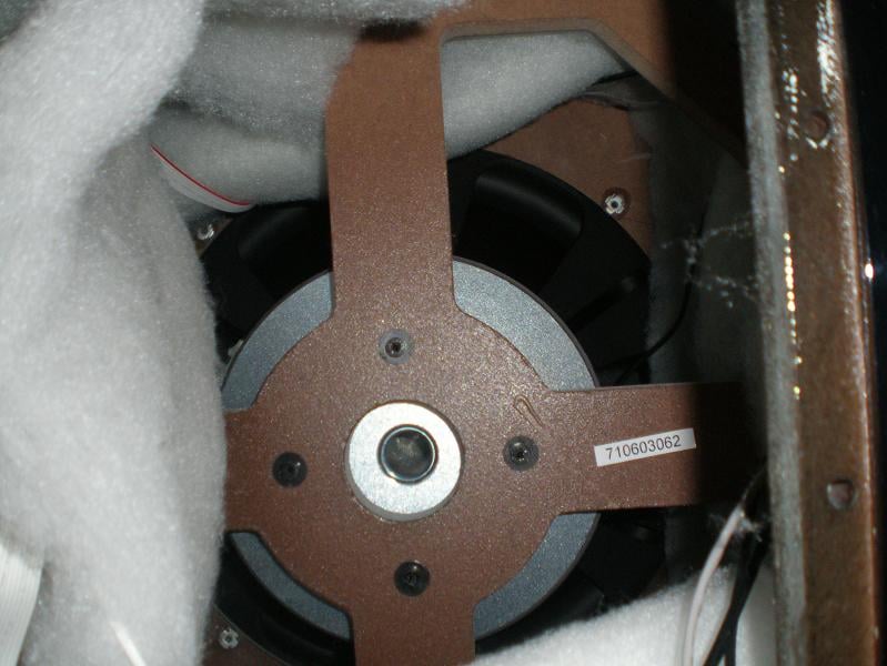
Usually I would have removed the driver for pictures and inspection, but I did not remove the DD18+ driver due to it being a rather involved affair including removing the amplifier, disconnecting the driver and servo sensor from the amplifier, unbolting the driver motor from the enclosure bracing internally, removing the grill and front fascia, removing all of the driver bolts, etc. I contented myself with inspecting the driver while it was still attached to and housed in the enclosure. Needless to say it is a high quality and robust unit. The motor is very large and heavy. It looks to be built on 2 roughly 9” diameter ceramic slugs and a very large and tall top plate. There is also a roughly 1” pole vent with a screen to catch debris before they enter the gap. The driver uses a 3” nominal voice coil in what appears to be an underhung arrangement where the voice coil is short and the top plate and magnetic gap are tall. This is a way to improve driver linearity with stroke by keeping the motor force more constant with respect to voice coil position and thus reduce harmonic distortion. The cast aluminum frame used is sturdy and well ventilated. The cone is light but stiff and strong. I am a fan of Rohacell composite cones for this reason, not to mention that they also happen to look great. The spiders are generous in size and the surround is as well suggesting that the driver is capable of plenty of stroke for demanding low bass transients. This is a very high quality driver.
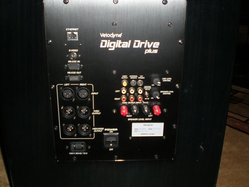
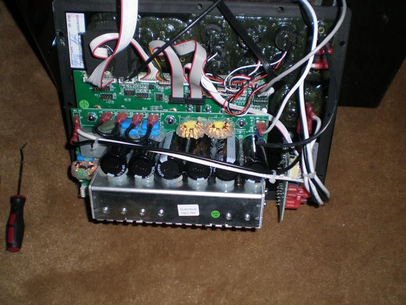
The amplifier itself appears to be of similar high quality and connects to the front panel control unit via a ribbon cable. Six large reserve capacitors were in evidence on the top circuit board as was a small aluminum heat sink which indicates that this is the power section. Another larger circuit board is mounted below the power section. During testing and use the amplifier face never got much more than warm to the touch implying that it is a very efficient design. Also the amplifier contains a simply staggering amount of input and output connection possibilities. Everything from balanced XLR ins and outs, to 12v trigger, to speaker level inputs, unbalanced RCA, serial ports and even an Ethernet port. There is even a USB port on the front panel. No one can accuse Velodyne of limiting your options that is for sure.
The enclosure of the DD18+ under review was a beautiful ebony gloss black finish in which you could still see wood grain if looking closely. Internally the enclosure has a very large window brace in the center which the driver motor is also anchored to with bolts. This ties every major panel of the enclosure together except for the back panel which houses the amplifier. There is also a generous amount of poly fill stuffing inside of the enclosure behind the driver and on the walls. During testing and use I noted no cabinet resonances or audible issues related to the cabinet even at the loudest drive levels. It is very solid and inert.
Velodyne Digital Drive Plus 18 (DD18+) Subwoofer Listening Session
For all of the listening sessions the Velodyne DD18+ was placed in the front right corner of the room firing into the corner about 4 inches from the walls. This places the subwoofer a little over 4 meters from the primary listening position. I have determined this to be the best available single subwoofer placement in the room for most units. Audyssey was run on the system to allow it to integrate the DD18+, which was then followed by a check and recalibration of the subwoofer and speaker levels prior to the listening sessions. I also had earlier done some in room testing of the EQ capabilities built into the DD18+ which had some interesting results that we will get into later in the review. I did not end up using the built in EQ, instead manually providing some extra EQ to help tame a severe peak at 45Hz due to the room acoustics that affects every subwoofer placed in the room. Audyssey did not provide enough correction alone to tame it. The DD18+ settings were as follows for all of the listening session: Low pass filter disabled, rumble filter set to 15Hz with a 6dB octave roll off which allows the deepest extension possible, night mode off and servo gain at its highest setting of 8.
DVD: 16 Horsepower - Live
I’ve been listening to this group for a long time and this recently acquired DVD captures a couple of powerful live performances towards the end of the group’s career before they disbanded into other projects. 16HP is a sort of folk rock group with a rather dark tinge to it, based around David Edwards powerful vocal performances and often make heavy use of a wide variety of instruments to craft their songs. Everything from accordion to double bass, drum set, various percussion instruments, piano, electric bass, slide guitar, mandolin, banjo, bazuki, etc, etc. Much of that variety is on display in the live performances captured on this DVD. The DD18+ clearly and cleanly resolved every bit of bass presented by the myriad of different instruments and drums with precision, providing ample weight and character to the sound while also providing power and punch where needed. I attempted to focus on the bass foundation present and what the DD18+ was contributing to the mix, but honestly after getting a couple of songs in, I started just enjoying the performance.
I also tried a few more bass intensive tracks from other music genre’s just to see how the DD18+ did with them. A few tracks from The Dillinger Escape Plan’s Miss Machine album and a couple of select Chemical Brothers tracks at rather high volume further confirmed that the DD18+ has stellar sound quality and presentation with music.
Blu-ray: Batman – Begins –The Dark Knight
After the DD18+’s
performance with music I was eager to experience what it could do with a
dynamic action movie. Since the look of the DD18+ reminded me of something that
Bruce Wayne would have in his collection I decided why not watch Batman Begins
followed by the Dark Knight, both of which offer not only a very powerful and
engaging audio track but also are enjoyable movies to watch. The master volume
was set to -15 for the entirety of both films.
I was eager to experience what it could do with a
dynamic action movie. Since the look of the DD18+ reminded me of something that
Bruce Wayne would have in his collection I decided why not watch Batman Begins
followed by the Dark Knight, both of which offer not only a very powerful and
engaging audio track but also are enjoyable movies to watch. The master volume
was set to -15 for the entirety of both films.
Throughout the various action and dramatic sequences of the films the DD18+ provided a stellar performance. Subtle background bass undertones were just that and when demanded the DD18+ provided a lot of power and room shake. On sections that contained deeply extended bass the DD18+ had generous extension that provided an extra feel or size to the sound that lesser subwoofers simply do not. As previously discussed the performance of the DD18+ as far as definition and ability to track notes is excellent. If there was any small caveat to the DD18+ performance it might be that it was not quite as sharply dynamic on a few parts as I recall they can be, the tumbler chase scene being one example, the gatling gun test, bankers shotgun blasts and the hospital explosion being others. My large listening room acoustics are such that it is very difficult for a single subwoofer, even a very capable and powerful one such as the DD18+, to handle alone so perhaps the DD18+ was being limited a little on a few extremely loud sections. Audio memory is a hazy thing at best so I can’t be sure and to be quite honest I’m stretching to find even that small caveat with the DD18+’s audible signature. It is that good. What I can be sure of is that the DD18+ always sounded composed throughout and easily produced one of the top performances that I have experienced from a single subwoofer in my room. Very deep bass was presented with apparent ease and fundamental tones or pitches of bass transients were spot on.
Velodyne Digital Drive Plus 18 (DD18+) Subwoofer Measurements and Analysis
The Velodyne DD18+ subwoofer was measured outdoors sitting on the ground with the microphone placed 2 meters from the front lip of the cabinet with the grill removed. The driver was facing directly at the microphone. The Jazz preset was used for the tests and configured with the low pass filter disabled, the rumble filter set to its minimum setting of 15Hz and 6dB / octave roll off to allow for maximum response extension and flatness, all EQ was defeated and the subwoofer volume was set to 35. All tests were conducted in this configuration, except for those tests purposely conducted to examine the effects of the built in functions or different operational modes.
Also note that two full test sets were conducted on the DD18+. One with the servo gain setting at maximum of 8 and the other with the servo gain setting at a minimum of 1. All other settings remained the same between the two.
The overall approach to this testing along with the equipment and software used is outlined in the article here.
Powered Subwoofer Testing Outline and Procedures Overview
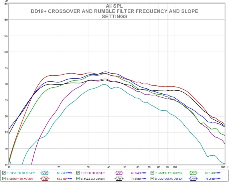
Velodyne DD18+: Effect of Low and High Pass Filter Settings
Above is the effect of various setting of the low pass and rumble filters on the DD18+’s response. There is quite a large amount of adjustment available with just these two settings.
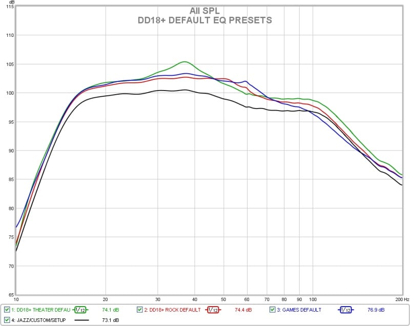
Velodyne DD18+: Effect of Movie EQ Preset
Above is the basic response of the preset EQ curves available from the factory. Most of them appear to add an overall signal boost. The theater setting adds a slight peak near 35Hz which seems to have a higher Q than one would expect. The Games preset adds a little boost to the 60Hz region.
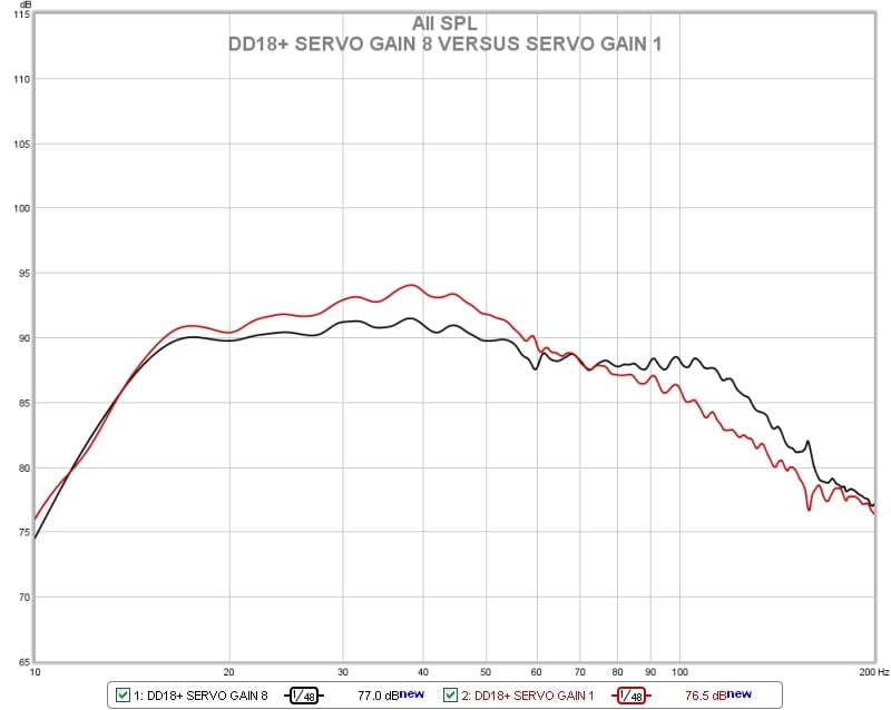
Velodyne DD18+: Basic Frequency Response as Tested
In the chart above is the basic response of the DD18+ at the two different servo gain settings. The red trace is with the servo gain at its lowest setting of 1. The black trace is with the servo at its highest setting of 8. As can be seen the maximum setting of 8 produces a flatter more extended response while the lowest setting of 1 produces a more rolled off and humped up response. The servo seems to be forcing the unit into a flatter response shape at the highest setting whereas the lowest setting is probably closer to the actual driver and enclosure response combination. Velodyne specifies the DD18+ as 14.4-120Hz +/-3dB and 8.8-300Hz overall with no tolerance given. With the servo gain setting at 1 the DD18+ only fits within a 6dB window from 14.6-70Hz. If the window is expanded to 10dB total the response fits in from 13-109Hz. With the servo gain at its maximum setting the DD18+ response fits within a 6db total window from 13.5-126Hz which is slightly better than Velodyne’s specification. Within a 10dB window the response is 12-150Hz. I suspect that this configuration is what Velodyne specs their response from. By 300Hz the response is about 20dB down and probably unusable regardless of the setting.
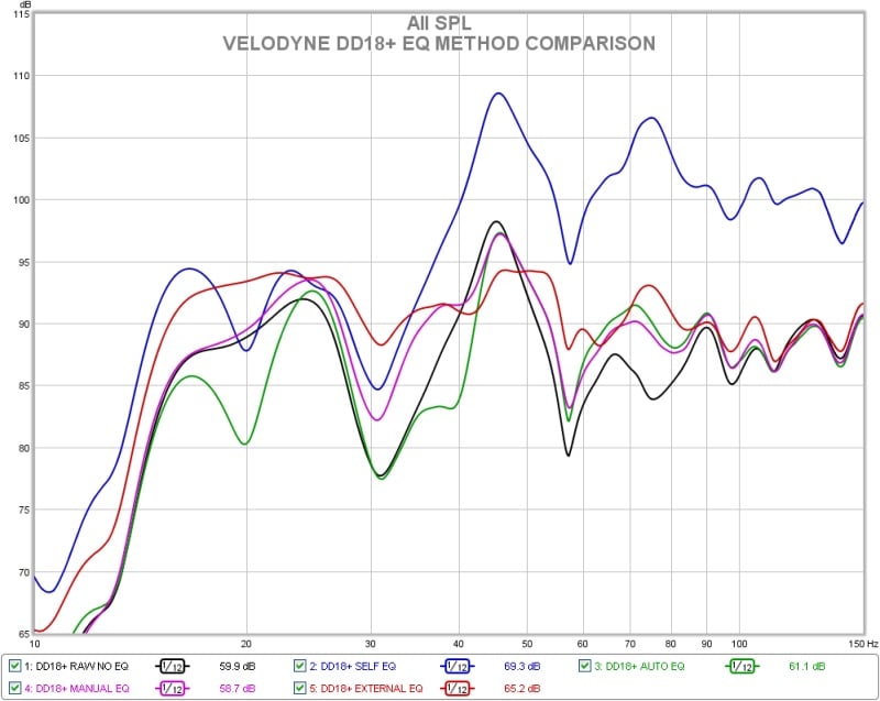
Velodyne DD18+: Internal EQ Results
In the above graph we have the results of equalizing the DD18+ in room. The black trace is the raw response in room as measured by my reference Earthworks M30 which as you can see is not very good to begin with and requires some taming being +/-10dB from 14-150Hz. The DD18+ was run through each of its equalization schemes to check the effectiveness and results with the Velodyne microphone in the same exact position as the M30 with the elements about ¾” apart. The result for the Self EQ scheme, which is the blue trace in the graph above, was very strange resulting a dramatic boosting of the upper range and an actual worsening of response to +/-12dB 14-150Hz. Next the Auto EQ routine was tried. This had better results than the Self EQ option but still wasn’t very effective. The worst response issue the 12db peak at 45Hz seemed to be ignored and some smaller cuts were made at 20Hz and 40hz. The resulting response was barely improved and fit within a +/-9.9dB window from 14-150Hz. Next the manual EQ option was attempted. This method allows you to manually adjust the EQ settings while the Velodyne on screen display shows the result on the response. This method had the best result and is represented in the pink trace on the graph. The response was improved to +/-7.5dB 14-150Hz using the manual EQ method. Finally I decided to see what equalizing with my regular unit a Behringer DCX2496 would do. This is the red trace in the graph above and is +/-3.7dB from 14-150Hz.
During the process of using the on board equalizer and display of the DD18+ in conjunction with my regular measurement system I noted that the frequency response plot shown inside of the Velodyne software looked much better than what my manual measurements did and also more curiously that some of the features appear to be shifted. I have provided an example below.
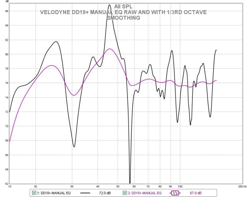
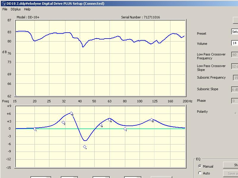
Velodyne DD18+: Software Response Shown Versus Actual Measurement
The above 2 charts show the measured response of the DD18+ with some manual equalization applied. The top graph in the bottom picture is frequency response as reported inside of the Velodyne software. It is showing a response variation of +/-2.5dB, or a 5dB total window from 15-200Hz. Any audio fanatic would be proud to have that response. The picture above the Velodyne chart is what my reference measurement system reported the DD18+ response as. I have scaled the 2 graphs as closely as possible for comparison. The black line is the raw measurement from the M30 with no smoothing and the pink trace is the same measurement with 1/3rd octave smoothing. Looks rather different eh? The black trace is +/-13.4dB from 15-150Hz. Even with 1/3rd octave smoothing the pink trace is still +/-6.4dB over that range. I had thought that adding the smoothing would better reconcile the two but it still doesn’t match up that well. Even more curious is the fact that many of the main features from the two measurements do not seem to match up. The Velodyne chart indicates a dip at 45Hz instead of the obvious peak. Again at 30Hz there is a bulge in output instead of a dip. Down below 20Hz the Velodyne software indicates a rising response, but my personal rig indicates a large drop off. Very odd indeed. I’m not really sure what to make of this. It almost seems as if the response as reported on the graph inside of the Velodyne software is offset ½ of an octave. Again both microphones were in the same position within ½” of each other. Certainly there can be differences attributable to the different test signals used and the way the data is presented but these seen here are rather large. If you do use the internal EQ of the DD+ series the manual method is by far the best option in my estimation.
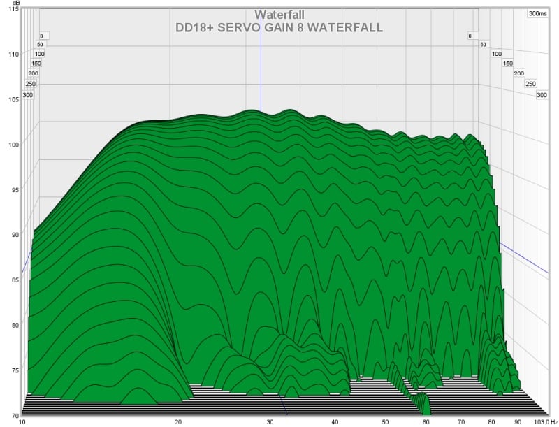
Velodyne DD18+: Waterfall Decay
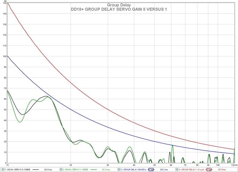
Velodyne DD18+: Group Delay
The response of the DD18+ in the time domain is rather uneventful and about as expected. There is clean decay across the full range until about 16Hz where there is a moderate increase due to the boost EQ being employed to extend the response and the corner of the high pass filter. Still it never breaks 1 cycle of delay even below 20Hz. There is negligible difference in this performance metric whether the servo gain is set to minimum or maximum.
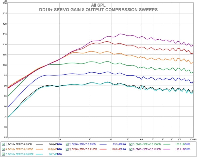
Velodyne DD18+ Servo Gain 8: Long Term Output Compression
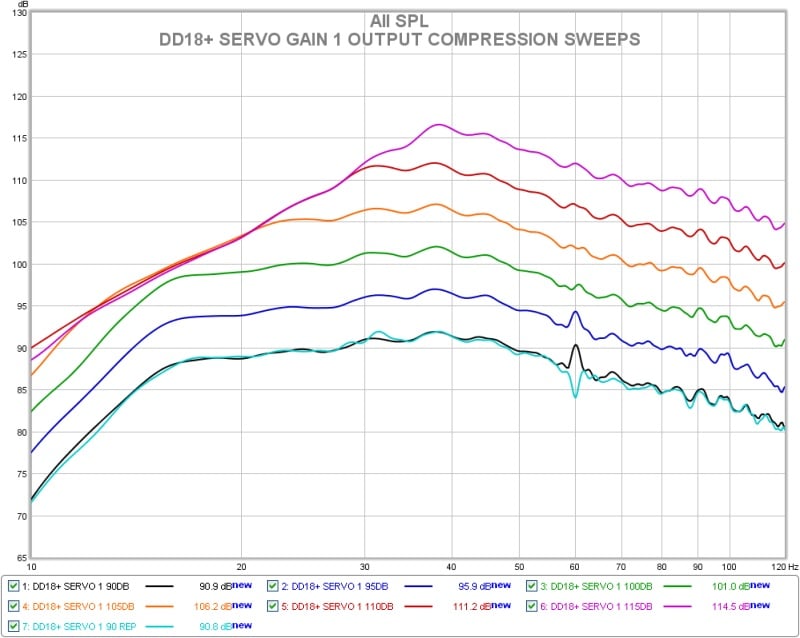
Velodyne DD18+ Servo Gain 1: Long Term Output Compression
The maximum long term output compression test for the DD18+ with the servo gain set to minimum and maximum both are presented above. Overall despite the response shape differences there is not much difference. Compression and output limiting kicks in first at about 16Hz where the response is being boosted the most and expands progressively from there as the output is increased and the subwoofer reaches the maximum output level that it can produce as configured. The output does not start compressing notably until the 105db sweep level. By the 115dB sweep level the deep bass is being limited heavily everywhere below 30Hz.
This is by far the most demanding test conducted on the subwoofers during testing and will reveal any issues with overload, port compression, port noise, driver distress, creaks, rattles, buzzes, etc. Additionally this is outdoors with just the subwoofer operating so there are no nearby walls or objects to vibrate and no upper frequency masking content from other speakers that would cover up or mask any noises from the sub. Any sort of audible issues with the subwoofer will be readily apparent. The most offensive noise that the DD18+ produced was a very slight warming to the tone in the deepest bass indicating increased distortion from high excursion of the driver. In room with other speakers operating and actual content this would probably never be noticed. That is it. Most subwoofers do start making obvious bad noise at some point. This subwoofer is as stable and composed as I have seen. It simply quits getting louder before it ever makes objectionable noise.
Velodyne Digital Drive Plus 18 (DD18+) Subwoofer Measurements Cont.
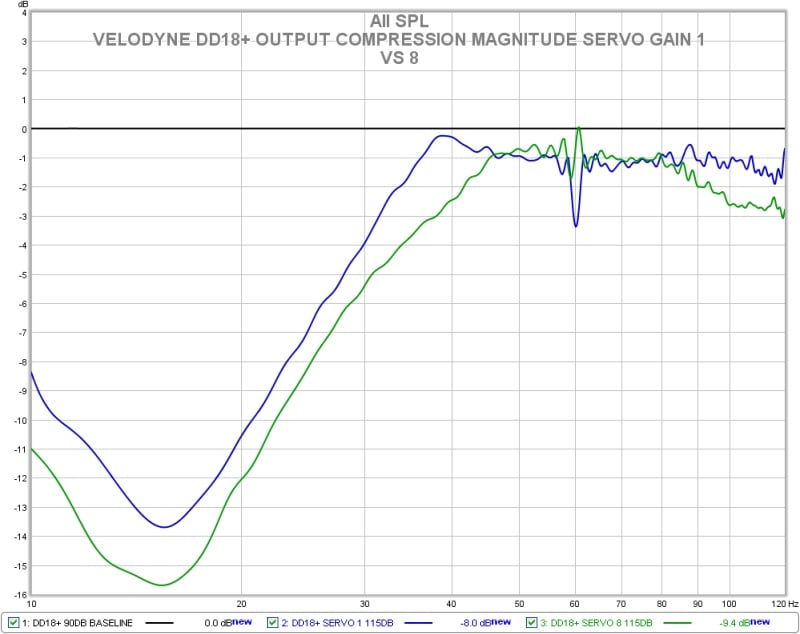
Velodyne DD18+: Output Compression Magnitude
Above we have another way of looking at the results from the output compression test. This shows only the amount of signal compression occurring during the nominally 115dB sweep level for both the minimum and maximum servo gain settings. The lowest servo gain setting appears to have advantage here but this is deceptive due to the flatter response of the highest servo gain setting producing higher output at the frequency extremes at the same basic sweep level. This is because the sweep level is referenced to 50Hz. In reality the difference is very small to nil.
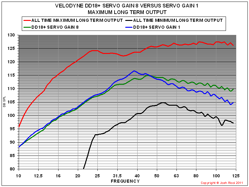
Velodyne DD18+: Maximum Long Term Output Level
Looking at the maximum long term output achieved for both the minimum and maximum servo gain settings shows that the output headroom is virtually identical below 30Hz. There appears to be some difference above that point but this is again probably deceptive because the response shapes start out differently. The 2 curves would likely converge further if an even higher input level were used.
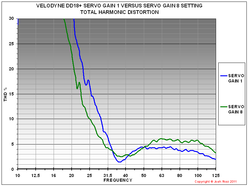
Velodyne DD18+: Total Harmonic Distortion
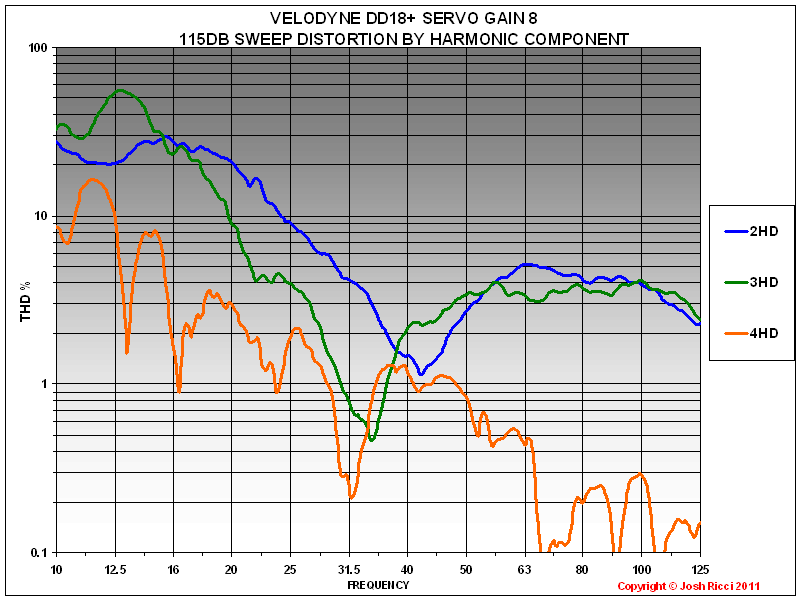
Velodyne DD18+ Servo Gain 8: 115dB Sweep Distortion by Component
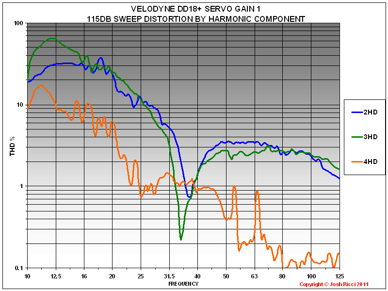
Velodyne DD18+ Servo
Gain 1: 115dB Sweep Distortion by Component
The information collected during the distortion measurements presented above, prove quite interesting. First Velodyne specifies that distortion is held below 0.5%THD during normal operation by the servo system. Perhaps it is but what is “normal” operation? Probably rather modest playback levels without much deep bass accounted for. Any subwoofer system I have ever measured the distortion for or seen test results for has had distortion that rises dramatically in the deep bass frequencies when the system is pushed towards its upper output limits. This is due to the increased demands for air displacement from the driver, passive radiator, ports or all of the above as the frequencies get lower. It is also very difficult to achieve enough of a signal to noise ratio at deep bass frequencies to measure the distortion without environmental noise heavily corrupting the data. This leads to the output needing to be increased to get the output out of the noise floor and or moving the microphone closer to the subwoofer to achieve the same effect which can cause problems of its own. I generally consider anything under 10% THD as acceptable in the 25-120Hz bass range and likely inaudible in most cases. Anything under 5% THD in that same bass range I consider low enough to not worry about entirely. In the very deep bass below 25Hz it is not uncommon to see THD levels rapidly rising and exceeding 30% and even 100% in some cases. I was completely unsurprised when the DD18+ exhibited the typical rise in deep bass distortion of a sealed system. Truthfully if the DD18+ had remained under even 15% THD below 20Hz at full output I would have been dumbfounded.
With that out of the way, what does the information in the distortion measurements tell us? The DD18+ does have very low distortion even while being pushed to its limits. It is well under 6% THD above 30Hz even during the 115dB output sweeps. With the servo gain dialed all of the way up it does not crack 10% until below 25Hz. The distortion is primarily composed of the second harmonic followed closely by the 3rd harmonic also. The second harmonic is generally held to be the least offensive audibly. With the very high output levels involved during the 115dB sweep this is a very good result. Also note that with many subwoofers there can be other noises that develop when driving them this hard that may not show up in the distortion measurements. The DD18+ was free from any of these. Like any other subwoofer or speaker the distortion performance is better at lower drive levels. During the 90dB sweep the THD is well below 5% until below 20Hz.
The most interesting take away is the comparison of the DD18+ with the servo gain at minimum versus with it at maximum. The lowest setting appears to have slightly lower distortion overall above 50Hz however remember that it rolls off much quicker in this configuration than with the flatter response of the maximum setting. This results in 2 to 4dB less output during the sweep over that range and could account for the slightly lower distortion since it is not being pushed as hard. Note what happens below 31.5Hz though. The distortion with the servo gain cranked all of the way up is significantly lower. The output is virtually the same since the DD18+ is well into the limiter in both configurations at that point, yet the THD with the servo gain at 8 is some 7-10% lower on average below 31.5hz. Also note that there is a significant reduction in the level of the 3rd harmonic distortion below 31.5Hz as well. That is a pretty big difference and indicates to me that the servo system is indeed making a large improvement to the deep bass distortion from the system. Overall the DD18+ distortion results are very good.

Velodyne DD18+ Servo Gain 8: CEA2010 2 Meter Groundplane RMS Results
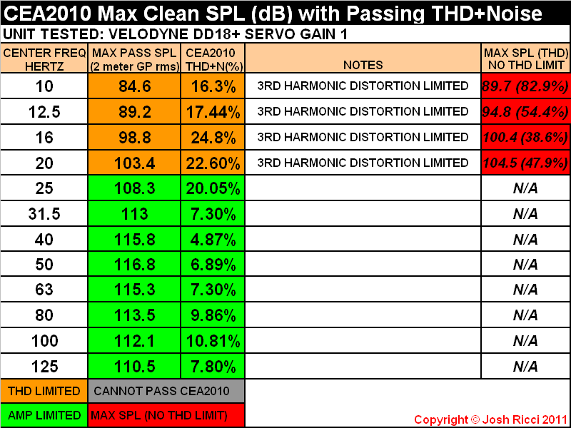
Velodyne DD18+ Servo Gain 1: CEA2010 2 Meter Groundplane RMS Results
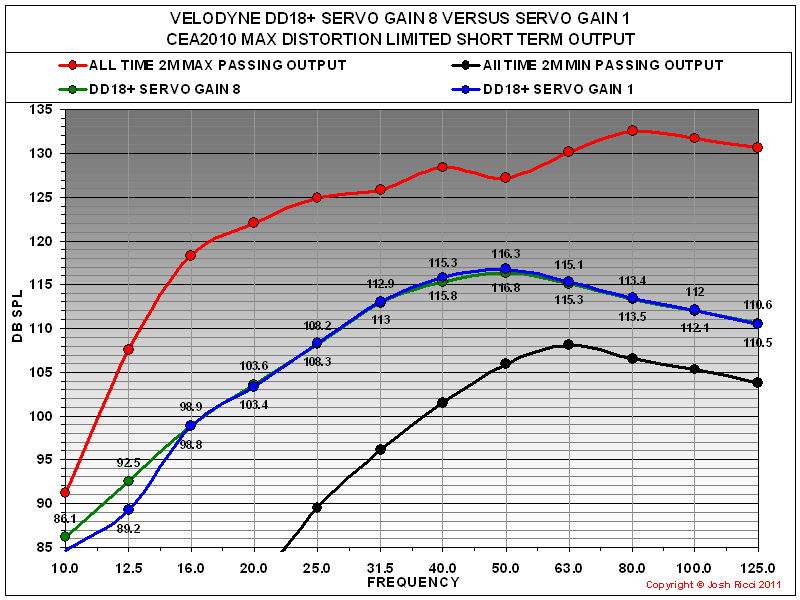
Velodyne DD18+: CEA2010 2 Meter Groundplane RMS Comparison
CEA2010 Results
Looking at the CEA-2010 maximum peak output of the DD18+ puts it in the upper middle range of all subwoofers ever tested and near the top of all sealed subwoofers. It produces output easily in excess of 110dB over the critical music range and offers impressive deep bass output as well mustering over 103dB at 20Hz and almost 99dB at 16Hz which is impressive for a sealed subwoofer. The DD18+ CEA-2010 output is amplifier limited above 20Hz and was distortion limited at and below that point. The DD18+ is the first commercial subwoofer that I have ever evaluated that was able to produce a CEA-2010 passing result at 10Hz. 86.1dB may not seem like much but any passing result at the 10 and 12.5Hz bands denotes rather prodigious deep bass output capabilities due to the amount of displacement involved to produce any meaningful output that low in frequency, not to mention that distortion must be under some amount of control as well. If distortion is ignored completely the DD18+ can almost muster 90dB at 10Hz.
The DD18+ exhibits virtually the same output whether the servo gain is cranked all of the way to 8 or at its minimum of 1 with less than a half of a dB’s difference from 16-125Hz. However an interesting thing to note is that at the 10 and 12.5Hz bands the DD18+ was able to record a passing result some 3db or so higher with the servo gain at maximum. After reviewing all of the information from the basic response, distortion, compression and CEA-2010 output, the DD18+ seems to perform better with the servo gain at its maximum setting. It offers flatter more extended response, lower deep bass distortion and no obvious tradeoff in output, which is what I assumed would be the case going in. I see no reason to operate it with this setting any lower. Also I don’t see any reason to set the DD18+’s rumble filter to anything other its very minimum setting of 15Hz with a modest 6db per octave roll off as this allows it the deepest bass extension, unless perhaps you are combining a system with different subwoofer types (ie. ported) or speakers and need to adjust the roll off rate to obtain a better total system response. In that case adjusting the HPF may help. Otherwise the DD18+ never had any issue with even the deepest bass test signals that were thrown at it and is probably the most well protected and limited subwoofer I have yet encountered. It was completely rock solid and seems capable of handling deep bass signals without reservation. I see no reason to limit the extension on a subwoofer this powerful, advanced and expensive. There was note in the manual about this possibly extending the life of the unit. With the 5 year electronics warranty I would not worry about it personally.
Suggestions for Improvement
The couple of nitpicks that I have with the DD18+ are the obvious ones. First and foremost is the $4999 sticker which is a lot of greenbacks no matter your financial situation and will place it well outside of the budget of many. I prefer at least 2 or more subwoofers no matter the situation to increase headroom and even out the room response which will end up being a lot of dough. The second gripe would be with the DSP and on board EQ system. It produced some very odd results which did not match up very well with what I recorded on my reference measurement system. In particular the self equalization scenario seemed to produce an erroneous result. Manually EQing seems to be the best scenario. Also the sheer amount of features, connections and user adjustment available on the DD18+ could be overwhelming for some, although I found that once I started installing the software it was much more straightforward than it looked at first glance. I give credit to Velodyne for the very thorough user manual and the ease of operation of all of the functions. Even the user software installed and ran right off of the bat and it was easy to use the supplied audio disc to measure and EQ the response or adjust the pre-set parameters. Sonically the one area I would like to see Velodyne look to improve on the next revamp is the top end extension and flatness above 100Hz which would allow it to crossover higher and integrate easier.
Velodyne Digital Drive Plus 18 (DD18+) Subwoofer Conclusion
Vel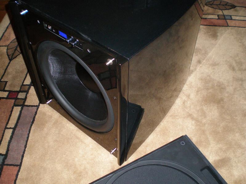 odyne has established a reputation as one of the premier high end
subwoofer manufacturers from having a very strong tendency toward placing sound
quality first and foremost and incorporating technological advancements to
improve product performance. Judging from the DD18+ it is easy to see why this
reputation is deserved. The DD18+ performs very strongly in every major
performance metric while also being very nicely appointed and finished. The
amount of features and connectivity built into the unit are almost
overwhelming. It is built using premium quality components but more importantly
the integration and application of the separate parts into the finished product
is top notch. Even the packaging was a cut above the usual as it should be on a
speaker in this price range. No matter what signal is presented to the DD18+
inputs it will reproduce it to the best of its abilities with excellent
reproduction and nary a hint of distress with even the most ridiculous
Hollywood low frequency effect.
odyne has established a reputation as one of the premier high end
subwoofer manufacturers from having a very strong tendency toward placing sound
quality first and foremost and incorporating technological advancements to
improve product performance. Judging from the DD18+ it is easy to see why this
reputation is deserved. The DD18+ performs very strongly in every major
performance metric while also being very nicely appointed and finished. The
amount of features and connectivity built into the unit are almost
overwhelming. It is built using premium quality components but more importantly
the integration and application of the separate parts into the finished product
is top notch. Even the packaging was a cut above the usual as it should be on a
speaker in this price range. No matter what signal is presented to the DD18+
inputs it will reproduce it to the best of its abilities with excellent
reproduction and nary a hint of distress with even the most ridiculous
Hollywood low frequency effect.
When taken in as a whole the DD18+ is at or very near the top of the heap of subwoofers I have had the pleasure to get acquainted with in all around performance. In fact, it was even the recipient of our 2011 Product of the Year Award for the Subwoofer category. The Velodyne DD18+ is a total package that offers extreme flexibility, user configurability, an eye pleasing façade, top notch, accurate sound reproduction, deep extension and plenty of output headroom for most situations and spaces. The integration of the parts and manner in which the total system performs is among the best that I have seen. This subwoofer has been optimized to the point that it simply will not emit an ugly sound no matter what you ask it to do and it still allows for a lot of output at the same time. It simply sounded great with everything. I owned a few Velodynes years back and have heard a few of the earlier HGS or DD models over the last decade and they have always sounded exceptional, but they sometimes fell a little bit short on output. Velodyne has made a major step forward in that regard with the new Digital Drive Plus line. In the deep bass the improvement seems to be such that a single DD+ has output corresponding to two of the previous model in the series or perhaps even a bit more. That is a huge difference. In fact the DD18+ is our first sealed subwoofer to achieve our Extreme room size rating. To wrap up, precision is the word that comes to mind to describe the DD18+. Most other subwoofers I have encountered simply do not seem to have the nth degree of total system optimization that the DD18+ does. If your budget supports it the Velodyne DD+ line is worthy of your consideration and highly recommended.
The Velodyne DD18+ receives the Audioholics Bassaholic "Extreme Room" rating, which means that this sub is recommended as maintaining adequate headroom in rooms or spaces of 5,000 cubic feet or more and/or for users who usually listen at higher volume levels. For further information in how we make these recommendations see the full article here.
See: Audioholics Subwoofer Room Size Rating Protocol
Velodyne DD18+Review
velodyne.com
Toll Free:
866-243-0789
MSRP: $4,999
The Score Card
The scoring below is based on each piece of equipment doing the duty it is designed for. The numbers are weighed heavily with respect to the individual cost of each unit, thus giving a rating roughly equal to:
Performance × Price Factor/Value = Rating
Audioholics.com note: The ratings indicated below are based on subjective listening and objective testing of the product in question. The rating scale is based on performance/value ratio. If you notice better performing products in future reviews that have lower numbers in certain areas, be aware that the value factor is most likely the culprit. Other Audioholics reviewers may rate products solely based on performance, and each reviewer has his/her own system for ratings.
Audioholics Rating Scale
 — Excellent
- — Very Good
- — Good
- — Fair
- — Poor
| Metric | Rating |
|---|---|
| Bass Extension | |
| Bass Accuracy | |
| Build Quality | |
| Fit and Finish | |
| Ergonomics & Usability | |
| Features | |
| Dynamic Range | |
| Performance | |
| Value |