
Loudspeaker Impedance, Series & Parallel Connection Basics
More often than not a question pops up in our forum about speaker impedance and the result of connecting multiple speakers to a single amplifier. Thus we have prepared this introductory tutorial to help clear up some of these questions.
The most common ways of hooking up more than one speaker to an amplifier channel are:
- Series Connection
- Parallel Connection
- Series-Parallel Connection (for more than 2 speakers)
There are pros and cons to each method which we will discuss herein.
To understand the differences, we must first explore the very basic principle of how electricity flows through a circuit.
Ohms Law: V = i * R where V = voltage, i = current, R = resistance (1)
A loudspeaker isn't a simple resistance because it is an electroacoustical-mechanical device which is usually governed by a complex passive crossover network comprised of inductors, capacitors and resistors. Thus the speaker system presents a complex impedance which varies with frequency and power level. "Complex" here means impedance is a vector quantity possessing both phase & magnitude.For simplicity sake, we shall model our system's impedance magnitude only, ignoring phase . As an example, let's look at an impedance curve (or modulus of impedance) of an actual loudspeaker (the Onix x-ls).
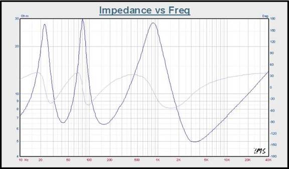
Graph 1: Sample system modulus of impedance
The impedance minimum 0f 6.56 Ω at 42 Hz indicates the vented box tuning frequency. There are two other local minima, found at 164 Hz (6.386 Ω) and 3.4 kHz (4.97 Ω). That the first two minima are proximal in magnitude indicates an efficient reflex action. The large impedance peak, found at ~ 850 Hz arises as a result the interaction of the crossover network's high- and lowpass sections, setting up a parallel resonance. The impedance phase swings between +39° and -54° across the audible spectrum. With a lowest magnitude minima value of 4.97 Ω, the system nominal impedance (per IEC standards) value would be 6 Ω.
Series Connections Basics
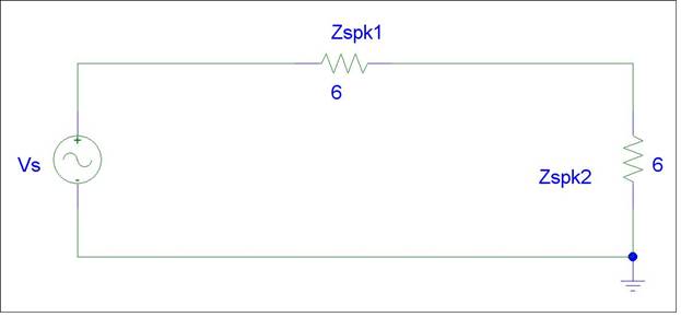
Schematic 1: Series Circuit
As you can see in our diagram above, we have connected Zspk1 and Zspk2 in series with our amplifier (Vs). Using Ohms law (1) we can calculate the following relationships:
Equivalent Impedance also known as the Thevenin Impedance where we short our voltage source (in this case our amplifier) to calculate the total load it will see from our two speakers connected in series.
Zeq = Zspk1 + Zspk2 (2)
For simplicity, we shall use identical speaker loads from the speaker we showed in the above example.
Hence, Zspk1 = Zspk2
Zeq = 6 + 6 = 12 ohms
Thus by connecting two speakers in series, the amplifier now sees double the load impedance. But how does this translate to power delivery?
In a series circuit, there is only one path from the source through all of the loads and back to the source. This means that all of the current in the circuit must flow through all of the loads and the current though each load is the same.
To calculate voltage drop through each load, we apply Ohms law: (1)
Vspk1 = i * Zspk1
Vspk2 = i * Zspk2
Next we apply Kirchoff's Voltage Law (KVL) which dictates the sum of the voltages within a circuit must equate to zero.
Thus we get the following relationship:
Vs = Vspk1 + Vspk2 or Vspk1 + Vspk2 - Vs= 0
Let's assign some arbitrary numbers to solve for the variables in our equations.
Vs = 10V
Zspk1 = Zspk2 = 6 ohms (as per our speaker example)
First we must solve for current in the circuit so we can calculate our voltage drops to each load.
Using KVL we write the following mesh equation:
-10V + i*(6) + i*(6) = 0
Solving for I, we get: i = 10 / 12 = 0.83A
Now we can solve for our load voltages using Ohms law (1):
Vspk1 = i * Zspk1 = 0.83A * 6 ohms = 5V
Vspk2 = i * Zspk2 = 0.83A * 6 ohms = 5V
Of course a more simplified method known as the Voltage Divider principle can be used for calculating voltage across loads in series circuits. Here is how we can quickly solve for Vspk2:
Voltage Divider Relationship: Vspk2 = Vs * (Zspk2) / (Zspk1 + Zspk2) (3)
Using KVL we check to see if the sum of our load voltages equal our source so that the total voltage summation in the circuit equates to zero.
-Vs + Vspk1 + Vspk2 = 0
-10 + 5 + 5 = 0
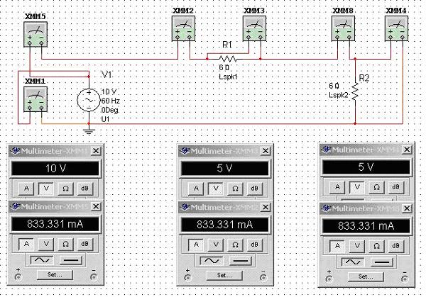
as you can see we correctly calculated our circuit voltages as KVL was satisfied. Working up a circuit model using Electronics Workbench (EWB) confirms this.
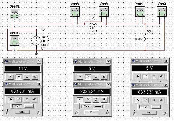
Schematic 2: Series Circuit
But what about power?
To calculate our power to each loudspeaker, we must first develop a relationship for power.
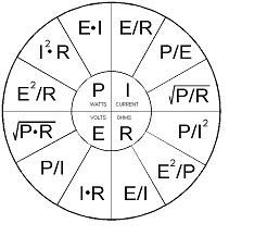
Here are three commonly used equations: P = V * i ; P = V^2 / R or P = i^2 * R (4)
![[pie]](../../../images/pie.jpg)
The Handy Dandy Ohms Law Pie Chart
Since we calculated all of our circuit voltages and current, we can find power with either of the above equations. Let's use P = V^2 / R only we shall represent R as Z for our loudspeaker magnitude.
Pspk1 = Vspk1^2 / Zspk1 = (5V)^2 / 6 = 25 / 6 = 4.17 watts
Pspk2 = Vspk2^2 / Zspk2 = (5V)^2 / 6 = 25 / 6 = 4.17 watts
Ptot = Pspk1 + Pspk2 = 4.17 watts + 4.17 watts = 8.33 watts
If we were to rework this example for just one 6 ohm loudspeaker connected to our amplifier, we would have seen the following power delivery to the loudspeaker:
Pspk = 10^2 / 6 = 16.67 watts since all of the voltage from our amplifier would have been delivered to the single loudspeaker load. Once again our model confirms this.
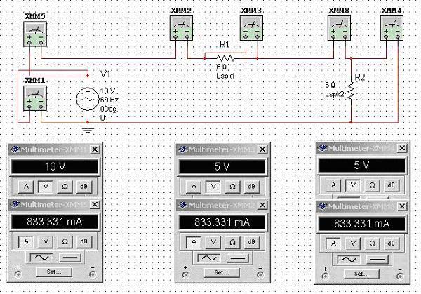
Schematic 3: Single Load
Thus connecting two speakers in series resulted in ½ the power consumption of just one speaker directly connected to our amplifier. This makes sense since the amplifier is now seeing double the load impedance and delivering only ½ the current.

So how does this equate to sound pressure levels?
Since we connected two identical speakers in series with our amplifier, each speaker only sees half the voltage drop across it thus as a result will see only 1/4 the power delivered to each speaker compared to a single speaker connected to our amplifier. The equivalent SPL now produced by each speaker is 6dB lower than if a single speaker were playing off the amplifier, for a combined overall -3dB drop. However, running two speakers effectively doubles the volume displacement compared with that of one speaker. Thus playback through the two drivers results in a 3dB gain. Adding this to the 3dB drop previously mentioned and the net overall sound pressure level will remain unchanged. Thus, playing two identical speakers connected in series off of a common amp (as opposed to playing just one speaker off that amplifier) results in no level drop, when compared to the single speaker case. This analysis, of course, ignores mutual coupling and any room-induced acoustical artifacts. However, if the speakers connected in series are not co-located and summing perfectly in the room, the net SPL would likely be up to -3dB lower than playing a single speaker off the same amplifier. The net SPL product in this case has a dependent relationship on distance between the speakers and frequencies they are destructively interfering in the room.
Modeling both a single-driver system as well as a series-wired, dual-driver system we see the dB spl plots are virtually identical.
![[zser12]](../../../images/zser12.jpg)
Graph 2a: Single driver, system model: Amplitude response. dB spl @1m/2.828Vac drive level, ref. to 20 μPa.
![[zser21]](../../../images/zser21.jpg)
Graph 2b: Dual- driver, series wired system model: Amplitude response. dB spl 1m/2.828Vac drive level, ref. to 20 μPa.
Loudspeaker Impedance, Series & Parallel Connection Basics - page 2
Parallel Connection Basics
Our next, more common method of connecting two speakers to a single amplifier is known as the parallel connection.
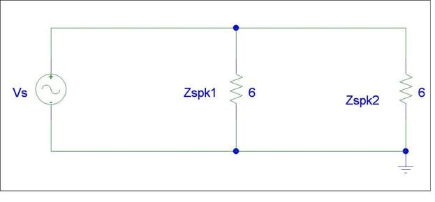
Schematic 4: Parallel Circuit
In parallel circuits, the voltage drop across each load is identical while the summation of the currents entering each node must equate to zero according to Kirchoff's Current Law (KCL). Thus we break up the circuit into two meshes where mesh #1 is comprised of Vs and Zspk1 and mesh #2 is comprised of Zspk1 and Zspk2.
Using KVL we write the following equations:
-Vs + Zspk1*(i1 -i2) = 0
Zspk1*(i2 - i1) + Zspk2*(i2) = 0
Letting Vs = 10V and Zspk1 = Zspk2 = 6 ohms, we can now solve for our unknowns
-10 + 6(i1-i2) = 0
6(I2-i1) + 6(i2) = 0
with some basic algebra, we solve for the currents using substitution.
6i1 - 6i2 = 10
-6i1 + 12i2 = 0 à i2 = ½(i1)
thus
i1 = 3.33A and i2 = 1.67A
to solve for Vspk1 we use Ohms Law and the following relationship relating to our circuit:
Vspk1 = Zspk1 (i2 - i1) = 6(1.67-3.33) = 10V
Vspk2 = Zspk2 * i2 = 6*1.67 = 10V
Of course there is always an easier way to solve for our unknowns. In parallel circuits we know that all of the elements in parallel with the source must share the same voltage as the source. Thus if we already know our loud impedances and source voltage, we can calculate our power draw to each load using the power equations we established in (4).
Pspk1 = Vs^2 / Zspk1 = 10^2 / 6 = 16.67 watts
Pspk2 = Vs^2 / Zspk2 = 10^2 / 6 = 16.67 watts
Alternatively (and referring to Schematic 5 as well as the Ohm's law pie chart above) Pspk 1,2 can be calculated by:
Pspk1 = Vspk1 * Ispk1 = 10V *1.667A = 16.67 Watts
Pspk2 = Vspk2 * Ispk2 = 10V *1.667A = 16.67 Watts
To calculate total power consumption we must add the power consumption of both speakers.
Ptot = Pspk1 + Pspk2 = 16.67 watts + 16.67 watts = 33.3 watts
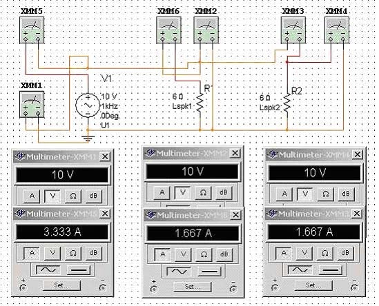
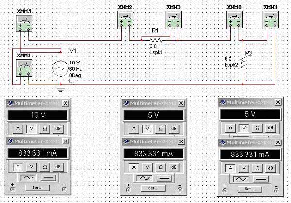
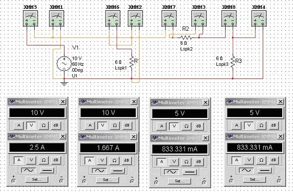
Schematic 5: Parallel Circuit
This is twice the power consumption of just one speaker connected directly to the amplifier and four times the power consumption of connecting the two identical speakers in series from our prior example.
To determine the load the amplifier will see when connecting two speakers in parallel, we again refer to the principle of Thevenin impedance by shorting our voltage source and deriving the following equation:
Zeq = Zspk1*Zspk2 / [(Zspk1 + Zspk2)] (5)
For more than two speakers connected in parallel (not recommended) the following relationship can be used:
1 / Zeq = 1/Zspk1 + 1/Zspk2 + ….. 1/Zspkn (6)

So how does this equate to sound pressure levels?
Since we connected two identical speakers in parallel with our amplifier, each speaker sees the identical voltage drop across it thus as a result will consume the same power delivered to each speaker compared to a single speaker connected to our amplifier. As a result, our amplifier is now taxed to produce twice the current into the equivalent load which is now ½ that of the single speaker connection. Thus the equivalent SPL produced by two speakers connected in parallel would be 6dB louder than a single speaker playing off the amplifier and 6dB louder than having two identical speakers connected in series to the amplifier . As before, this analysis, of course, ignores mutual coupling and any room-induced acoustical artifacts. However, if the speakers connected in parallel are not co-located and summing perfectly in the room, the net SPL would likely be more like +3dB louder than playing a single speaker off the same amplifier. The net SPL product in this case has a dependent relationship on distance between the speakers and frequencies they are destructively interfering in the room.
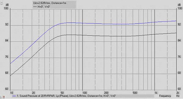
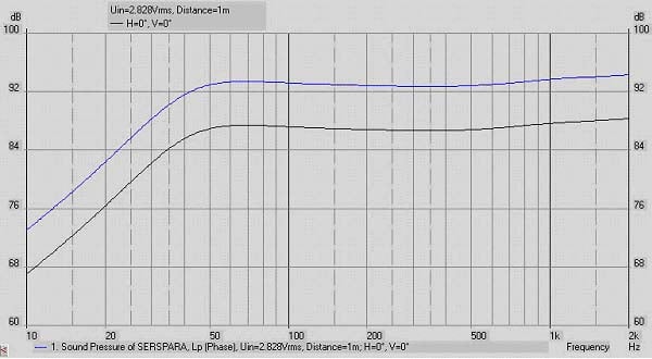
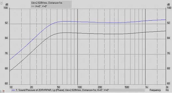
Graph 3: Single driver and parallel- wired dual driver systems model: Blue line: parallel- wired 2-driver system; Black line: single-driver system; dB spl @1m/2.828Vac drive level, ref. to 20 μPa
Series - Parallel Connection Basics
This is usually the less common method of connecting multiple speakers to a single amplifier, but is definitely recommended if more than two speakers are to be connected since it will help ensure the equivalent impedance doesn't drop below the minimum recommended load impedance specified by the amplifier manufacturer.
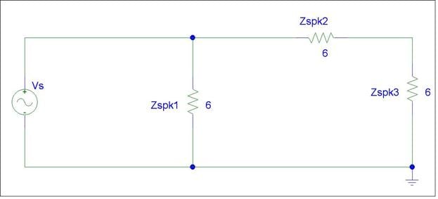
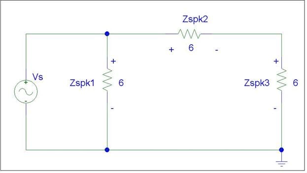
Schematic 6: Series-Parallel Wiring
As we can see in the diagram above, Zspk2 and Zspk3 are in series (2). Thus we can add them and replace them with a new impedance which we can refer to as Zspk2'.
Thus: Zspk2' = Zspk2 + Zspk3
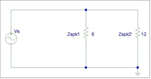
Schematic 6b: Series-Parallel Wiring equivalent
To find the equivalent loud impedance seen by our amp, we add Zspk1 and Zspk2' in parallel (6) and yield the following result:
Zeq = (Zspk1 * Zspk2') / (Zspk1 + Zspk2')
Substituting our 6 ohm values, we yield an equivalent impedance of:
Zeq = (6 * 12) / (6 + 12) = 4 ohms
But how much power is delivered to each of the three speakers wired in the series / parallel scheme shown above?
To answer that question, we must recall the knowledge we established about series and parallel networks.
Since Zspk1 is in parallel with Vs (our amp), we can easily calculate power using EQ (4)
Pspk1 = V^2/Zspk1 = 10^2 / 6 = 16.67 watts
Since Zspk2 and Zspk3 are in series, with each other but their combined value is in parallel with Zspk1, we know the voltage drop across both of them must equal the voltage drop of Zspk1 and Vs. Remember Zspk2 = Zspk3, we know the voltage drop across each of them must be equal.
Hence:
Pspk2 = 5^2 / 6 = 4.167 watts
Pspk3 = 5^2/6 = 4.167 watts
Ptot = Pspk1 + Pspk2 + Pspk3 = 16.67 + 4.167 + 4.167 = 25 watts

Schematic 7: Series\Parallel Circuit
 So how does this equate to sound pressure level?
Because we connected three identical speakers in a series-parallel combination with our amplifier, Zspk1 sees the equivalent power of just one speaker connected to our amp, while Zspk2 and Zspk3 each see ¼ of the power of a single speaker connection. In the Vs-Lspk1 mesh we have the equivalent of the single driver circuit seen in Schematic 3. The Lspk2 & 3 mesh is the equivalent of the dual-driver, series-wired circuit illustrated in Schematic 2. Summing the acoustical output of the 3 sound sources wired electrically in this series-parallel combination will produce a +6dB gain when compared with the output of a single driver. This of course assumes the three speakers are playing without any acoustical cancellation issues in the room. However, if the speakers connected in series-parallel are not co-located in close proximity, the net SPL would likely be more like +1.76dB higher than playing a single speaker off the same amplifier. The net SPL product in this case has a dependent relationship on distance between the speakers and frequencies they are destructively interfering in the room.
Graph 4: Single driver and series-parallel wired triple driver systems model: Blue line: series-parallel wired triple driver systems; Black line: single-driver system; dB spl @1m/2.828Vac drive level, ref. to 20 μPa
Tabulated below is a comparison of series vs. parallel connections for identical speaker impedance loads compared to a single speaker load.
Comparison of Different Connection Methods
|
Metric |
One Speaker |
Series Connection (two speakers) |
Parallel Connection (two speakers) |
Series-Parallel |
|
Equivalent Impedance |
Zspk |
2 * Zspk |
0.5 * Zspk |
0.67 * Zspk |
|
Voltage |
Vs |
0.5Vs for Zspk1 & Zspk2 |
Equal to Vs for all loads |
Vs for Zspk1, 0.5Vs for Zspk2 & Zspk3 |
|
Current |
Is |
Equal for all loads (Is/2) |
Equal for all loads (Is) |
Is for Zspk1; Equal for Zspk2 & Zspk3 (Is/2) |
|
Power Consumption |
Pspk |
0.5 * Pspk |
2 * Pspk |
1.5 * Pspk |
|
SPL NET Diff |
0dB |
0 dB |
+6dB |
+6dB |
|
SPL NET Diff |
0dB |
-3dB |
+3dB |
+1.76dB |
So which connection method is better?
This depends on a number of variables. If the amplifier isn't capable of safely driving low impedance loads, than parallel connecting two speakers can result in overloading the amp and possibly damaging it. In this case, it is usually better to connect only one speaker to the amp or two in series if distributed audio is the goal. Series connecting of speakers should only be done with identical speakers to avoid inconsistent resultant sound. Connecting a pair of speakers in series will usually degrade the sound quality since the speaker in series with the first one is subject to frequency response variations from being presented with a complex load impedance as opposed to being directly coupled with the amplifier. The extent of the degradation depends upon the complexity of the speaker design, amplifier design, and listener sensitivity.
If the amplifier is robust enough to act as an ideal voltage source where it can double power when the load impedance halves, than this is the preferred connection method since it will maximize power delivery, SPL and minimize system frequency variations typical of the series connection method.
In some cases where an installer would like to connect multiple subwoofers off a single power amp, the series connection can still work out quite well, especially if each sub is already low impedance. Despite the net SPL loss of 3dB, you now have twice the surface area using two subs which will likely yield more impressive output while also keeping the power amp and loudspeakers in check to not be overdriven.
How do I know if my receiver speaker A / B terminals are wired in series or parallel?
This is usually quite easy to determine. Simply connect a pair of speakers to the SPK A terminals. While listening to a source, press the SPK B selector or Select SPK A + B. If you no longer hear sound, then the receiver has wired SPK A / SPK B in series. If you still hear the source than these connections are made in parallel.
How do I know if my receiver / amplifier is capable of driving low impedance loads?
Check with the manufacturer ratings to determine the minimum safe load impedance it can handle and stay within their recommendations as closely as possible. Realize however there is more to the difficulty of a loudspeaker load represents to an amplifier than an absolute impedance rating. This discussion goes beyond the scope of this article but may be revisited in a future article.
Summary
If you connect two identical speakers in electrical series but acoustically in parallel, there'll be a net gain of 0 dB when compared to a single driver system's output. Connect two drivers both in electrical & acoustical parallel and the overall net gain would be 6dB compared to the single speaker connection, likewise for the 3 driver series-parallel combination If you plan on connecting more than three speakers to a common amplifier, a combination of series-parallel connection represents the best compromise for maximizing SPL while minimizing amplifier strain. This of course all assumes no loudspeaker power compression, adequate amplifier headroom is available, no room cancellation, comb filtering issues or boundary gain are considered. In reality, there will be acoustical cancellations and augmentations at certain frequencies which cannot be accounted for in the context of this analysis.
Recommendations
Always consult the owner's manual or the manufacturer of your equipment to understand the product limitations. Make sure you verify the polarity of your speaker connections. If you are wiring two speakers in parallel, make sure the (+) of each speaker connects to the (+) terminal of your amplifier, while the (-) terminal of each speaker connects to the (-) terminal of your amplifier. If you are wiring two speakers in series, make sure the (+) terminal of the first speaker connects to the (+) terminal of the amplifier, the (-) terminal of the first speaker connects to the (+) terminal of the second speaker, while the (-) terminal of the second speaker connects to the (-) terminal of your amplifier, and so on. See the illustration below for further clarification.
Schematic 8: Basic Wiring Diagram
![[box]](../../../images/box.jpg) If you plan on connecting a more complex distributed audio system in your home, we advise you to consider using impedance controlled speaker switch boxes (such as the Niles Speaker Selector product shown to the right) which ensure proper load balancing of your speaker system when connecting to your amplifier(s) or employ a combination of a series-parallel wiring scheme to ensure the equivalent impedance doesn't drop below the amplifier manufacturers minimum recommendations. Remember its better to add or replace amplifiers if your application exceeds your amplifier(s) capability of delivering clean, unclipped power to your audio system. Multichannel distribution amplifiers are also worth considering when implementing more elaborate multiple speaker connections for distributed audio applications.
If you plan on connecting a more complex distributed audio system in your home, we advise you to consider using impedance controlled speaker switch boxes (such as the Niles Speaker Selector product shown to the right) which ensure proper load balancing of your speaker system when connecting to your amplifier(s) or employ a combination of a series-parallel wiring scheme to ensure the equivalent impedance doesn't drop below the amplifier manufacturers minimum recommendations. Remember its better to add or replace amplifiers if your application exceeds your amplifier(s) capability of delivering clean, unclipped power to your audio system. Multichannel distribution amplifiers are also worth considering when implementing more elaborate multiple speaker connections for distributed audio applications.
Gene manages this organization, establishes relations with manufacturers and keeps Audioholics a well oiled machine. His goal is to educate about home theater and develop more standards in the industry to eliminate consumer confusion clouded by industry snake oil.
View full profile