
Loudspeaker Power Ratings: What's the Deal Part I?
There are two basic ways in which you can destroy a loudspeaker with power; thermally or mechanically. Everyone is familiar with the concept of being able to burn a loudspeaker. It gets too hot, and the voice coil wire burns, or worse, something else (like the cone) catches on fire and burns. We all go shopping with “How many watts can it handle?” This is like living in a vast desert with only a few filling stations and wanting to know your cruising range in miles. We ask how big is the tank, and not how many miles we get to the gallon. (What is the efficiency?)
Let us review a few very simple concepts regarding power handling.
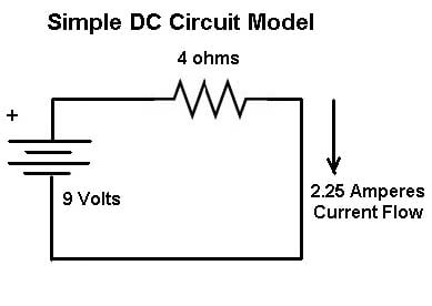
In a simple DC circuit, the calculation of power is simple and straight forward. We have a voltage source, a battery. A resistance (like a voice coil) and if we put the battery across the voice coil a current (I) will flow through the coil that is directly proportional to the Voltage (V) and the resistance (R). V=I*R or V/I = R or I = V/R, otherwise known as Ohm's law. We can calculate the power the load (R) dissipates as either P=V*I or P=I2*R or P=V2/R. The power which flows from a battery into a connected resistance does not vary in intensity with time, unlike music into a loudspeaker.
It’s all in the Voice Coil
 All voice
coils have the property of electrical resistance. Only into an electrical resistance can power be dissipated. All voice coils (conventional ones) have the
property of inductance (Le) making their impedance rise with increasing
frequency. (Power cannot be dissipated
into an inductance, and inductance has the property of lessening the current
flowing through the voice coil as frequency increases.) When we measure the DC resistance of a voice
coil, we apply a direct current (Zero Hertz) and measure the resultant voltage
across and current through the voice coil.
At very low frequencies not close to the loudspeakers resonant
frequency, this DC resistance predominates the speakers impedance (Z). Impedance is a term we use to describe the
resistance to electrical current as it varies with frequency. (We can think of this as AC instead of DC
resistance). This Impedance includes not only resistance, but Inductance and
Capacitance as well. These three qualities,
resistance, Inductance and capacitance together in combination with a
loudspeakers Motor Force and mechanical losses produce what we call the
Impedance magnitude curve. Now, you are
likely wondering what the heck this has to do with Power handling. The answer in brief is a whole lot. The reason is because it reveals much about
the amount of current actually supplied to and absorbed by the speaker which in
truth, is a far more consistent way to determine actual power than the use of
voltage.
All voice
coils have the property of electrical resistance. Only into an electrical resistance can power be dissipated. All voice coils (conventional ones) have the
property of inductance (Le) making their impedance rise with increasing
frequency. (Power cannot be dissipated
into an inductance, and inductance has the property of lessening the current
flowing through the voice coil as frequency increases.) When we measure the DC resistance of a voice
coil, we apply a direct current (Zero Hertz) and measure the resultant voltage
across and current through the voice coil.
At very low frequencies not close to the loudspeakers resonant
frequency, this DC resistance predominates the speakers impedance (Z). Impedance is a term we use to describe the
resistance to electrical current as it varies with frequency. (We can think of this as AC instead of DC
resistance). This Impedance includes not only resistance, but Inductance and
Capacitance as well. These three qualities,
resistance, Inductance and capacitance together in combination with a
loudspeakers Motor Force and mechanical losses produce what we call the
Impedance magnitude curve. Now, you are
likely wondering what the heck this has to do with Power handling. The answer in brief is a whole lot. The reason is because it reveals much about
the amount of current actually supplied to and absorbed by the speaker which in
truth, is a far more consistent way to determine actual power than the use of
voltage.
First off, most woofers have a lot of voice coil inductance. That means that as the frequency increases (goes higher) the magnitude of the impedance also grows higher. By the time we are at the crossover point for most woofers, most of the AC resistance to current flowing through the Voice coil (VC) is not due to resistance, but inductance. Let’s take a look at the impedance magnitude curve for a typical woofer with voice coil inductance varied from 2 to 6 millihenries.
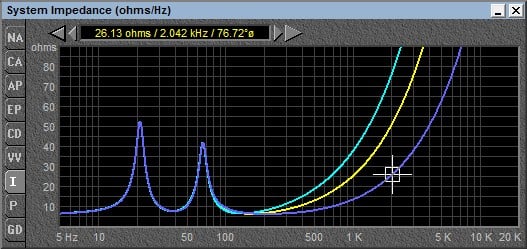
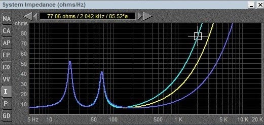
Loudspeaker impedance change vs Frequency
Notice at the Cursor, the frequency is 2000hz, and the Impedance magnitude varies from 26 to 76 ohms. The only difference between these three speakers is their inductance (Le). As you can see, at a high enough frequency, the DC resistance of the speaker makes almost no difference in its overall impedance magnitude. If the force acting on a speaker is as theory tells us:
F=BLI (Force in Newtons) = B(Tesla)*L(Meters)*I(Amperes)
Then it stands to reason that the woofer with the higher inductance (and therefore higher Impedance) will not only absorb less power at high frequencies, but it will be less efficient at high frequencies, something I can attest to after designing hundreds of loudspeakers.
Now suppose we test these three speakers using Pink Noise which is band-limited from 20 to 20,000 Hz. Which of the three speakers do you think will yield the highest power handling figure? (Hint: The one which absorbs the least amount of current).
Below is a measured impedance of a two way vented speaker system.
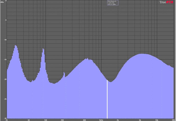
measured impedance 2-way system
How Loudspeaker Impedance is Read
As we can see by examination, the magnitude of the plot varies drastically with frequency. A trained eye will note that this is a vented system from the dual impedance peaks below 100hz. That the box tuning of this system is at about 50 Hz (the low point between the two peaks), and that there is a bad cabinet reflection as evidenced by the impedance peak just over 200 Hz. This up and down Impedance magnitude is caused by a combination of factors. The dual Low Frequency impedance peaks are indicative of a woofer in a vented box. The rise to 500 Hz is caused by woofer voice coil inductance. The dips at 1500 and 20K Hz are due to the interaction of the speakers with the crossover network. So, how do we calculate power if the Impedance is not constant?
(We don’t, we just look at the low point, and see if it is closer to 4 or 8 ohms!)
So, if the
Impedance of this speaker at 160hz is 8 ohms, and the music covers all the
range of frequencies within this curve, how do we know what power is REALLY being
dissipated in the speaker system? We
don’t. So, for the sake of
simplicity, we PRETEND the system is purely resistive, and invariant, and that
the power in Watts it is consuming is equal to Voltage squared divided by 8
ohms (V^2 / 8). We use the term “Nominal
Impedance” to cover our behinds with this half truth.
As we can clearly see, except for a few lows in the curve, most of the time the actual Impedance is higher than 8 ohms which gives us an APPARENT power handling much greater than the real power handling, and that is, as far as the marketing department tells us, a good thing. (So, how much power can this speaker handle the customer asks the salesperson...) Why muddy the waters with analysis and questions? If we were to measure the power handling as the equivalent current (I) squared times resistance (R) (I^2*R), we get a far different figure for power handling indeed, a much lower one the marketing department (and our customer) would definitely disapprove of.
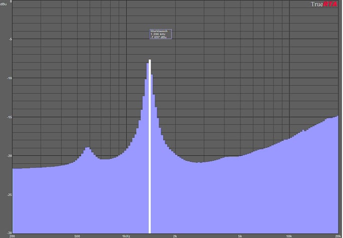
loudspeaker impedance vs frequency
Let’s take a look at the above curve. We can see this high frequency driver has a resonance at 1.4khz (location of the peak). So, if we wanted to calculate power as simply V2/R, we would pick a sine wave (single frequency tone) of 1.4khz, and pretend the power were going into 8 ohms, when in fact the magnitude of the impedance here is more than 30 ohms, 4 times what it is at 2.7 kHz “Great” says Marketing, lets measure this speaker at 1.4khz, and put a really big number out there! Problem is, before we can actually burn this voice coil, we are just going to break the speaker driving it at 1.4 kHz alone. At resonance, the speaker is mechanically most efficient, so it needs little real power (I squared times R) to move a great deal. In fact, if we wanted to test a speaker without burning it, and see how it would fail mechanically when stressed, powering the speaker with a single frequency at the resonance would be a good test to do.
So, this stuff is complicated. What are we as sophisticated consumers to do?
Interpreting the Measurements – Anything Goes?
All these speaker companies abide by the same measurement standards when they publish their power handling data right? Oh, if only we lived in a perfect world. Sorry, but no. There are several standards in use around the world, and in fact all the standards are compromised to allow easy collection of measurement data. The Electronic Industries Association standard (EIA RS-426B) the Audio Engineering Society has a standard (AES2-1984) The European International Electro technical committee has a standard (IEC 268.5) Brazil has its own standards as does the US, Japan, and the European Community, and they are all slightly different. This is not to say that everyone abides by these standards or reports them accurately. So how does one decide what is real and what is not? Without access to a lot of technical data, the question of power handling is a difficult and complex one to answer, and we are only scratching the surface of this subject.
There are two technical terms we now must come to grips with. RMS (Root Mean Square) and Crest factor (Peak Power divided by RMS power). RMS is the AC heating equivalent of invariant DC power. Since music is an alternating signal (representing the alternating compression and rarefaction of air we perceive as sound), we must reproduce it with a signal whose voltage varies quickly with time. A single frequency, which sounds completely constant in amplitude, actually varies from zero power to its peak value from tens to tens of thousands of times per second, depending on the frequencies of the signal. RMS is an expression that comes from the mathematical equation used to find the square root of the mean of the squared values. For those of you who are inclined to examine the math without getting headaches, there is an excellent description of this on Wikapedia @ http://en.wikipedia.org/wiki/Root_mean_square
For those of us not so inclined we can think of it as the average value, but in fact it is not the average value as the peaks add more power than the lower than average values, so we would find our intuition on this point fails us. (Which is why we need to do the math!)
Most test signals start with either pink noise (equal energy per octave – an octave being a doubling or halving of frequency) or white noise (equal energy per unit hertz) and shape it with frequency selective filters so it more accurately approximates the spectral content of music. Then the crest factor (difference between the signal peak value, and RMS value) is set to a standard, usually 6 db. A 6 db crest factor means the RMS value of the power test signal is ¼ of the peak (instantaneous value) of the signal. It makes it easy for us engineers to measure the value, by letting us use a multimeter instead of a computer program and some far more expensive and complex electronics, but at the same time it does not accurately reflect the much higher dynamic range (difference between the softest and loudest sounds) of actual music. If we compare the RMS value with the peak value of the signals in real music, we find that the CREST FACTOR is often more than 20db! That means if we use a test signal having a 20db crest factor, to test a 1000 watt RMS speaker, we will need a power test amp capable of driving the load with 100,000 watts peak power! To make matters worse, when one does use actual musical signals in their test setup, we find that it is near impossible to measure the RMS value of the signal! So, the compromise we make is to choose an unrealistically small CREST FACTOR which allows us the use of inexpensive meters, and smaller power amplifiers than the use of a typical musical program would require.
You Cannot Change the Laws Of Physics
 Basic
physics: we have a device which has a voice coil, immersed in a steel magnetic
circuit, and which has voltage across and therefore current flowing through
it. Above a certain level of power,heat
is entering the system faster than it
can escape. As a result, the VC heats up
because the power applied creates heat in excess of what the speaker can
physically dissipate. This situation is
fluid, as over time as the steel parts of the speaker become hotter, they
become less prone to absorbing the heat generated at the voice coil. Eventually
the speaker will fail. The escape route for the heat is through the air
surrounding the voice coil (VC), into the metal surrounding structure, and into
the air around it. The greater the surface
area of the metal the VC is exposed to, the lower the thermal path
resistance. So, if we have a 0.375” thick top plate that is 4 inches in
diameter, versus the same thickness 2 inches in diameter, we should have about ½ the
thermal resistance, and (we hope) twice the power handling. What else matters? The thickness and material (aluminum is
better than copper in this regard) of the electrical conductor used to wind the
VC. The larger the conductor, the lower
the current density in it. (If our conductor is doubled diameter, it will have
4 times the surface area (and mass) and can take 4 times as much current for
equivalent conductor heating. In short,
what size VC wire is used? This is a
large reason why woofers handle more power than do high frequency devices. A typical woofer can handle hundreds of watts
of power, while a typical tweeter may handle tens of watts. So, why not use large conductors in tweeters
too? Because of the mass inherent in a
large diameter conductor. If we don't
make a moving system light enough for it to change direction 40,000 times a
second (as is required to reproduce 20Khz) then it will not cover the frequency
range we need it to. Furthermore, if we
double the speakers mass, we lower the efficiency by 6db, requiring 4 times the
power for the same acoustic output. So
if we get 4 times the power handling, and need 4 times the power for the same
acoustic output, we have accomplished nothing except inefficiency. (In reality
double the mass will also limit the upper high frequency limit, so it is doubly
harmful). This balancing act is one all speaker designers must come to grips
with.
Basic
physics: we have a device which has a voice coil, immersed in a steel magnetic
circuit, and which has voltage across and therefore current flowing through
it. Above a certain level of power,heat
is entering the system faster than it
can escape. As a result, the VC heats up
because the power applied creates heat in excess of what the speaker can
physically dissipate. This situation is
fluid, as over time as the steel parts of the speaker become hotter, they
become less prone to absorbing the heat generated at the voice coil. Eventually
the speaker will fail. The escape route for the heat is through the air
surrounding the voice coil (VC), into the metal surrounding structure, and into
the air around it. The greater the surface
area of the metal the VC is exposed to, the lower the thermal path
resistance. So, if we have a 0.375” thick top plate that is 4 inches in
diameter, versus the same thickness 2 inches in diameter, we should have about ½ the
thermal resistance, and (we hope) twice the power handling. What else matters? The thickness and material (aluminum is
better than copper in this regard) of the electrical conductor used to wind the
VC. The larger the conductor, the lower
the current density in it. (If our conductor is doubled diameter, it will have
4 times the surface area (and mass) and can take 4 times as much current for
equivalent conductor heating. In short,
what size VC wire is used? This is a
large reason why woofers handle more power than do high frequency devices. A typical woofer can handle hundreds of watts
of power, while a typical tweeter may handle tens of watts. So, why not use large conductors in tweeters
too? Because of the mass inherent in a
large diameter conductor. If we don't
make a moving system light enough for it to change direction 40,000 times a
second (as is required to reproduce 20Khz) then it will not cover the frequency
range we need it to. Furthermore, if we
double the speakers mass, we lower the efficiency by 6db, requiring 4 times the
power for the same acoustic output. So
if we get 4 times the power handling, and need 4 times the power for the same
acoustic output, we have accomplished nothing except inefficiency. (In reality
double the mass will also limit the upper high frequency limit, so it is doubly
harmful). This balancing act is one all speaker designers must come to grips
with.
There are many small details the speaker designer must come to grips with when selecting materials for his design that influence the power handling of the loudspeaker. What kind of space does manufacturing need between the voice coil and the steel parts? 0.010”? 0.020” The greater the distance between the VC and the steel parts, the longer the path the heat must travel and the hotter the VC will get. Use too small a gap, and the reject rate will soar from rubs. Too large a gap, and the material efficiency will suffer as the magnetic lines of force must travel greater to jump the gap and energize the voice coil. Too small a gap, and when heat expands the copper or aluminum wire, it will scrape the top plate causing a failure. The size of the gap will also determine how much turbulence is in the gap, forcing cool air to flow over the VC taking away heat. Too much turbulence and the distortion becomes high, too little and the power handling suffers.
What kind of temperature do we use in the enamel which insulates the conductor (which without, all VC's would be one big short). Do we use 155 degree C wire? 180 degree, 200 degree or 220 degree? Use the highest, and suddenly we find it is taking forever to solder the wire ends to the flexible lead out wire (we call them pigtail leads) and manufacturing wants to have the engineers taken out back and shot. Or maybe with the highest temperature handling wire we find our glue does not stick to the wire.
What kind of glue do we use? Almost everyone I know in the speaker manufacturing business keeps their own formulations a secret. There are several classes of adhesive in wide use, among them Phenolic Buterols and one component heat cured Epoxies. Choose the highest temperature epoxy, and now we find we have to bake it in the oven for two hours instead of 10 minutes. (The production manager is loading his gun, while the accounting department is asking you for a meeting outside the building near the grassy knoll.) Unfortunately for them, they can't shoot me, because there are too many witnesses. The production personnel are outside on the grassy knoll, since there is no wire to use in the voice coils because the purchasing manager can't buy the 220 degree C wire without an 8 week lead time. (Did I mention my job was a lot of fun?)
Let’s suppose that somehow we have managed to dodge the bullets (maybe our production manager is just out of practice) and we get our VC to handle 500 degrees Fahrenheit of heat before it fails. WOW. OK, so now our 8 ohm speaker which had a DCR of 6.2 ohms at 20 degrees C, is suddenly 500 degrees F, or 260 degrees C. If we measure the DCR of the speaker, we now find that this voice coil is now 12 ohms. So our 8 ohm speaker is now a 16 ohm speaker, and instead of pulling 1000 watts out of the VOLTAGE amplifier, it is pulling 500 watts only. Now for our third vocabulary word of the day: COMPRESSION.
YouTube Discussion: The Truth about Matching Amplifier Power to Loudspeakers
What’s in Store for Part II of This Article?
In the next segment we will talk more about the effects of compression, how it affects the quality of the sound your loudspeaker reproduces, and how a 500 watt speaker can be broken with 100 watts, or endure 1000 watts based solely on the test signal chosen to drive the speaker.
(An excellent and scientific treatment of resistance variation with temperature is available at Wikapedia too.) http://en.wikipedia.org/wiki/Electrical_conductivity
About the Author
Paul Apollonio was born in Brooklyn NY in April 1957 and has worked in the Audio business as a design Engineer since he graduated College with a BS in Electronic Engineering Technology from Trenton State College, Trenton NJ in 1983. He has worked designing loudspeakers for among others, M&K Sound, JBL, Genesis Physics, Bertagni Electroacoustic Systems, Radian Audio, Ground Zero, Selenium, and B-52 Pro Audio. Paul has traveled from Russia to China to Brazil teaching and practicing the art and science of loudspeaker design. He is currently President of his own consulting company, Procondev, based in Downey California.
He may be contacted at papollonio@yahoo.com .