
Inductor Coil Crosstalk Basics
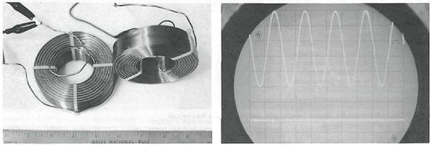
Inductor coils. The author used the two larger coils for the crosstalk experiments.
Proper Orientation For Optimal Performance
As a fledgling electronics buff I gathered together the usual hodgepodge of spare parts, old TV's and all the other electrical odds and ends that youngsters bitten by that particular bug seems to collect. Among my most prized possessions were 2 25 lb. spools of insulated, 12 AWG copper wire. Their weighty status didn't spare them however from featuring in many of my early experiments.
One day, I managed to connect one of the spools to an old kitchen radio and the other spool to an ancient driver of unknown origin. Much to my astonishment music popped out of the old driver! I also found that by changing the orientation of the two spools the driver's acoustic output would vary substantially. I didn't know at the time that I was observing the phenomenon of mutual inductance coupling.
Although the experiment ended when the radio finally conked out in a magnificent plume of smoke, my observations were far more lasting and would later gain new substance and serve me well in my loudspeaker design efforts. In this article I'll discuss a more recent experiment investigating the phenomenon of mutual inductance coupling as it applies to inductor coils used in passive crossover networks.
Magnetic Personalities
Like most loudspeaker designers, I am constantly on the lookout for cost-effective methods of lowering the noise floor of the systems I design. Crossover networks, when improperly designed and/or laid out (component-wise) are a proven, significant contributor to a system's noise picture. In the case of inductor coils there exist a handful of ways they can generate unwanted noise. First among these being mutual coupling or "crosstalk" as perhaps it is better known. Before proceeding, however, a very brief look at the physics of an inductor is in order.
Imagine for a moment uncoiling an inductor and straightening out the wire. When a steady current, I, flows through the wire a magnetic field is created. By the Biot-Savart law:
If the formula looks a bit troublesome, no need to worry as the key point to remember here is that a wire carrying a current will always set up a magnetic field.
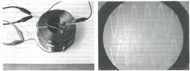
Figures 2, 2a: For my mutual inductance experiment, I hooked one coil to a function generator to provide a sinusoidal signal and connected the other to an oscilloscope. The left hand photos (Figs. 2 - 7) depict the various coil arrangements, while the right-hand photos (Figs. 2a - 7a) show the corresponding oscilloscope readings. The top waveform represents the voltage fed to the coil, while the bottom is the crosstalk reading. Note the substantial crosstalk when the coils are stacked one on top of the other.
The 12" ruler at the bottom of the left-hand figures is for scale.

Figure 3, 3a: There is still substantial crosstalk when locating the coils proximally and in the same plane.
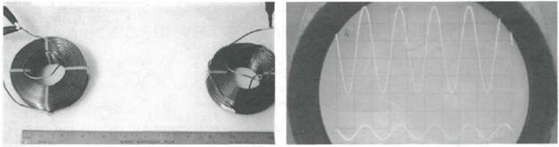
Figure 4, 4a: Increase the distance between coils and crosstalk decreases.
Figures 5, 5a: Coils in close proximity and oriented as shown above demonstrates crosstalk on par with that shown in Figure 3, 3a.
Now imagine coiling this wire into a single large loop, which we'll call coil 1. Place it next to another loop, which for simplicity sake we'll call coil 2 with a diameter equal that of coil 1. Energize coil 1 with, for example, a sinusoidal signal and it will setup a magnetic field. The flux,  , of which will link coil 2. This flux will, in turn, set up an induced emf (measured in volts) in coil 2. This induced emf equals the rate at which the magnetic flux of coil 1 changes with time.
By Faraday's Law:

Where there is voltage (in this case the emf) and resistance, as found in any piece of wire, there exists, of course, current.
A second way to express the emf that arises in coil 2 is:
Coil 2 emf = 
Where i is the current flowing in coil 1, t is in seconds and M is the mutual inductance proportionality constant, expressed in Henry's. Where M:
Essentially then, the current, changing with time in coil 1 sets up a magnetic field that links coil 2. In turn an induced emf, given by Faraday's law, appears in coil 2.
Test Setup
The magnitude of coil 2's emf depends not only on the distance from coil 1 but also the physical orientation of coil 2 to the direction of coil 1's magnetic flux. To verify this second point I set up a simple experiment. As my test coils I chose 2 virtually identical 3mH air core inductors (Figure 1). To coil 1 I connected a function generator, which provided a sinusoidal signal source. The second coil I connected directly to my oscilloscope. (In each photo the top waveform is that of the voltage fed to coil 1 and the bottom waveform is that of the voltage measured at coil 2.) The results clearly show that although putting sufficient space between the coils will certainly minimize crosstalk, there exists a far better solution, particularly where space is at a premium.
Figures 6, 6a: Distancing the coils helps minimize crosstalk substantially.
Figures 7, 7a: Where tight quarters do not allow much space between the coils, consider this arrangement, which provides for optimal results.
By orienting the coils as shown in Figure 7 you can reduce crosstalk to immeasurably low levels, even if they're close enough to touch as they were when the photo was taken.
Talkative Neighbors
You needn't worry if you don't have a function generator and/or an oscilloscope. In the past I've used whatever signal source I could conveniently feed through my power amp: CD, FM radio, tapes , etc. ( with the amp's output properly terminated, of course).
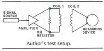
Figure 8: Test Setup
As for the measuring device, you can use an oscilloscope, a multimeter, a mid-range driver, a woofer or even Walkman style headphones. I wouldn't recommend using a tweeter. Assemble your test setup as shown in Figure 8 and simply move coil 2 around until you get no more signal at your measuring device. And of course if you have no test equipment available, just orient your two coils as shown in Figure 7. That's all there is to it! Don't forget to take into consideration your driver's voice coil is also an inductor when you plan the location and orientation of your crossover network inside your cabinet Locate them improperly and your inductors and voice coils will become undesirably talkative neighbors! The improvements gained by properly orienting your inductor coils are substantial and are well worth the time and effort.
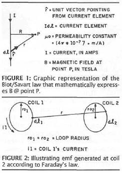
Figure 9