
How a Class D "Digital" Amplifier Works
A1400-8
Most audiophiles and enthusiasts have grown up with at least a basic understanding of what an amplifier does. It takes a tiny alternating electrical signal that represents the moment-to-moment variations of musical frequencies and their amplitudes (volume levels), and increases their strength many times so they're powerful enough to drive the cones and domes of speakers back and forth to generate air pressure variations (waves), which replicate the original sound waves. Musical tones vary as slowly as 16 times per second (16 Hz)—a very low pipe-organ note—to as fast as 15,000 times per second (15 kHz) or more—the highest harmonics of a cymbal or a violin, for example.
Hi-Fi Analog
Amplifiers
 Until quite recently, the majority of high-fidelity audio
amplifiers were analog, and most were of a type called Class A/B. What does that
mean? Perhaps one of the easiest ways to understand how an analog audio
amplifier works is to think of it as a kind of servo-controlled “valve” (the
latter is what the Brits call vacuum tubes) that regulates stored up energy
from the wall outlet and then releases it in measured amounts to your
loudspeakers.
Until quite recently, the majority of high-fidelity audio
amplifiers were analog, and most were of a type called Class A/B. What does that
mean? Perhaps one of the easiest ways to understand how an analog audio
amplifier works is to think of it as a kind of servo-controlled “valve” (the
latter is what the Brits call vacuum tubes) that regulates stored up energy
from the wall outlet and then releases it in measured amounts to your
loudspeakers.
The amount being discharged is synchronized to the rapid variations of the incoming audio signal. This weak AC signal is used to modulate a circuit that releases power (voltage and amperage) stored up by the big capacitors and transformer in the amplifier’s power supply, power that is discharged in a way that exactly parallels the tiny modulations of the incoming audio signal.
This signal in the amplifier’s input stage applies a varying conductivity to the output circuit’s transistors, which release power from the amplifier’s power supply to move your loudspeaker’s cones and domes. It’s almost as though you were rapidly turning on a faucet (you turning the faucet is the audio signal), which releases all the stored up water pressure—the water tower or reservoir are the storage capacitors-- in a particular pattern, a kind of liquid code. For our purposes, that’s all we need to know about analog amplification.
Digital
Amplification
Basically, a digital (Class D) amplifier takes an incoming analog signal and converts it into a digital representation comprised of pulse widths. Although there are a number of different design variations, Class D amplifiers are essentially switching amplifiers or Pulse Width Modulator (PWM) designs. The incoming analog audio signal is used to modulate a very high frequency Pulse-Width Modulated (PWM) carrier that works the output stage either fully on or off. Later on, this ultra-high-frequency carrier must be removed from the audio output with a reconstruction filter so that no ultra-high frequency switching components remain to corrupt the audio signals.
Differences in
Pulse-Width and Pulse-Code Modulation
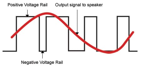
A digital amplifier’s operation
is a little like the way a CD or digital recorder works with PCM (Pulse Code
Modulation), the basis of all digital audio-recorded media. In PCM digital
recording (a CD, for instance), the digital sampling ADC (analog-to-digital
converter) “describes” the incoming analog voltage and frequency with a digital
code of ones and zeroes. But in a digital amplifier, the Pulse-Width
Modulator describes a low-frequency audio signal as the “widths of a pulse” so
many milliseconds wide. (A high frequency would be a narrower pulse, fewer
milliseconds wide -- see diagram). Once the analog audio signal (the curving red
sine wave overriding the pulses) is “described” in terms of pulse widths, it is
amplified and then converted back to analog form. During that process, a
reconstruction filter must remove all the on-and-off pulses, leaving only the
lower frequencies that represent the audio signal.
As Axiom’s chief
R&D engineer Tom Cumberland describes it, a digital amplifier is a “power
DAC”, and of course a DAC (Digital-to-Analog Converter) is the basis of all
digitally recorded media, whether we’re talking about CDs, hi-res audio, Blu-Ray
soundtracks, DVD video, and so on. The view of some that “all digital amplifiers
are crap” is not true. In fact, the clock rate of a good digital audio amplifier
is typically in the range of 350 to 500 kHz (that’s 500,000 Hz). (Axiom’s A1400
digital amplifier uses a 450-kHz clock frequency.) By contrast, even the
highest-resolution digital audio system (DVD-Audio and a variant used for
Blu-ray soundtracks) runs at 192 kHz, which is far below the clock rate of a
good digital amplifier.
Different Forms
of Class D Amplification
Though we may think that “digital” means all
the circuits in a digital amplifier work in on/off pulses, in fact there are a
number of different types, including digital amplifiers that have analog
elements.
A digital amplifier will have either analog or digital inputs. Good digital amplifiers with analog inputs can use analog feedback networks to lower the amplifier’s distortion, in much the same way that a Class A/B analog amplifier uses a negative feedback network to lessen the distortion. However, a digital amplifier that accepts only a digital input must rely on the incoming digital signal to lower distortion.
Feedback
Networks Why feedback networks? The reason they are used is that
all parts in an amplifier have “tolerances,” which means that any particular
part has a range or value in which it operates. Anyone who has examined such
basic parts as resistors may have noticed they are specified as being “5%” or
“10%” resistors, which means the specified resistor value is accurate within a
range of 5% or 10%, respectively. Consequently, because of these variations in
parts, a feedback network “looks at” the outgoing signal from the amplifiee --
the one that goes to your loudspeakers --and compares it to the incoming audio
signal at the amplifier’s inputs. Any deviation in value away from the incoming
signal is a distortion, so the negative feedback network applies inverse
correction to compensate.
Why feedback networks? The reason they are used is that
all parts in an amplifier have “tolerances,” which means that any particular
part has a range or value in which it operates. Anyone who has examined such
basic parts as resistors may have noticed they are specified as being “5%” or
“10%” resistors, which means the specified resistor value is accurate within a
range of 5% or 10%, respectively. Consequently, because of these variations in
parts, a feedback network “looks at” the outgoing signal from the amplifiee --
the one that goes to your loudspeakers --and compares it to the incoming audio
signal at the amplifier’s inputs. Any deviation in value away from the incoming
signal is a distortion, so the negative feedback network applies inverse
correction to compensate.
There are even differences in the operation of digital amplifiers.
For example, the “ICE” digital amplifiers developed by the Ice Power division of Denmark’s Bang & Olufsen use a very complex negative feedback system due to parts tolerances. B&O holds patents on its “ICE” amplifier, which is basically a Class D switching design (Pulse Width Modulator) with variants that B&O claims reduces distortion to levels associated with Class A amps, while retaining the high efficiency of Class D switching designs.
“IR” (International Rectifier) is the system used by Axiom Audio in its A1400 digital amplifier. Axiom worked with International Rectifier to keep parts tolerances held to the very minimum amount, so that very little negative feedback would be used to correct for anomalies in the output. This approach also made the amplifier more robust in its operation without being subject to oscillations or instability.
Axiom and IR developed new silicon output devices that drive the MOSFETs in the output stage in such a way as to produce a perfect Pulse Width Modulated square wave at the output before the reconstruction filter.
Pros and Cons of
ICE and IR Digital Amplifiers
One of the downsides to using a complex
negative feedback network in a digital amplifier of the type used in ICE designs
is a potential loss of efficiency (around 83%). Performance may also suffer because of a
slower clock rate.
In an IR type of digital design, which uses very little negative feedback or none at all, the clock rate is higher and efficiency increases. Moreover the high efficiency is combined with high power delivery and higher overall resolution. At full output, Axiom’s A1400 digital amp runs at about 95% efficiency (by comparison, class A/B analog amplifiers run between 50% and 60% efficiency; the remainder is wasted in heat).
 Special thanks to Axiom
Audio for allowing us to reprint this article.
Special thanks to Axiom
Audio for allowing us to reprint this article.