
Switching Amplifiers: The Technology and the Issues
This article started because a good friend of mine dropped a Panasonic SA-XR50 switch-mode amplifier to me for some basic bench test. This article will NOT be a review of that unit, but an investigation into some of the issues that are happening with this technology.
When I put this unit on the bench it was noted that the out-of-band noise components were so high that they interfered with all of the in-band measurements I was trying to make. In-band measurement of this class of amplifiers must be done with special filters that severely attenuate the out-of-band components preventing interference with in-band measurements.
But the major focus of the article will not be concerned with in-band measurements, but other equally important issues. I have been lucky enough to get Mike Danielson, who is primarily responsible for the DDX™ family of switching amplifiers, and Bruno Putzeys, formerly with Phillips and currently chief engineer, R & D, for Hypex to contribute their expertise to this article.
Measurements
In order to obtain the best possible accuracy of readings, I managed to get my hands on a LeCroy oscilloscope with a set of true differential probes for the best possible accuracy. Most scopes are O.K. for a differential measurement at low frequencies but higher frequency content requires a true differential probe set as the one LeCroy supplied. This is crucial for accurate measurement of the unit in question since the speaker outputs are differential outputs as opposed to the usual linear amplifier outputs, which are "unbalanced". In addition, I utilized a CD player's SPDIF digital output playing a CBS CD1 test disc to provide the 1 kHz test sine wave. The following scope shot and FFT plot (figure 1) is shown below:
Please note the following: The Red trace shown above is from a signal generator and is shown to demonstrate what a typical sine wave looks like coming out of a linear device. The trace in yellow is the actual 1 kHz sine wave from the Panasonic SA-XR50 driving an 8 ohm resistive load, at a power of approximately 5 watts rms. The lower trace shown in Orange is the FFT plot of the Panasonic SA-XR50 output (shown in yellow). Please note the following: #1 on the plot is at 1 kHz and referenced to 0db. #2 is at 90 to 110 kHz and is approximately - 20db down from the 1 KHz fundamental. (Note: This is possibly one of two things; switching power supply ripple or noise shaping, I suspect noise shaping.) # 3 is at approximately 350 kHz and is approximately - 25 db down from the 1 kHz fundamental, and #4 is at approximately 700 kHz and is approximately - 35 db down from the 1 KHz fundamental.
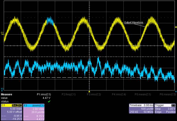
The scope shot provided in figure 2 has "zoomed in" on a small part of the output 1 kHz sine wave output wave to show the maximum output ripple, which is approximately 4 volts peak to peak at approximately 100 kHz.
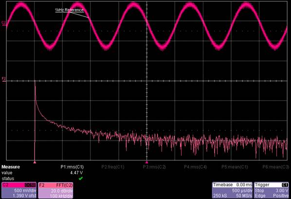
The next scope and FFT plot (figure 3) shows the "reference sine wave from our signal generator. Note the lack of out of band components.
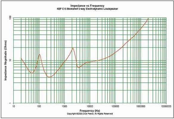
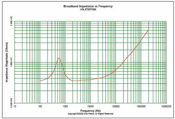
As we can see from our data there is a fair amount of out of band components from the output of the Panasonic receiver. So what does this mean when this energy hits the loudspeaker? I asked this question to loudspeaker designers and they have informed me of several facts. For the typical dynamic loudspeaker the impedance increases and is inductive, as the frequency rises above 20 kHz, so the power that develops across the tweeters voice coil is rather small. Will this cause Intermodulation distortion in the audio band? The math says no because the frequencies are too high, and the amount of power developed from the ultrasonic frequency components is low. So it appears that these higher order components should not damage your loudspeaker or cause I.M. distortion in the audio band. Some of the electrostatic loudspeakers are capacitive at higher frequencies in the audio band, but at ultrasonic frequencies the transformers used in the electrostatic loudspeakers will be inductive / resistive and by definition represent a high impedance load at ultrasonic frequencies. Will the frequency components at 350kHz and 700kHz interfere with AM radio band reception? Well, it might; if the radio or antenna is placed in close proximity to the speaker leads.
Please refer to the following two graphs supplied by Dick Pierce of one speaker and one tweeter showing the impedance of the speaker and tweeter out to 2 Mhz.
Switching Amplifiers: The Technology and the Issues - page 2
Feedback from Industry Professionals
So is there any problem here at all? The first and foremost problem I see here is consumer audio has no standard for grounding, and these out of band artifacts from the switching amps could well "pollute" the grounds of any equipment connected to the unit. For any digital input this may not be critical, for any analog inputs the effect could well be much more severe. However Mike Danielson has said the following " Your comments on lack of grounding standards in consumer audio and polluting other systems are dead on, but the signal will not fold back into the audio band as noise. The filters that raise the sampling frequency 8x to the output are carefully designed to avoid this and are used specifically to shift any audio band noise up above the audio band, this is exactly how DACs work. Test equipment how ever does not respond gracefully to this noise."
This is true, but we should note that DACs usually come with a low pass output filter to attenuate those artifacts by 40db or more.
Further Comments on grounding and PCB layout from Bruno Putzeys:
"A practical problem that pops up is that we can no longer use the chassis as a Faraday shield in applications that have large HF signals (such as class D amps) or high impedance circuits (volume control). Instead, local shielding connected to audio ground should be used.
The difficulty lies in audio folks' startling inability to make good circuit board layouts. If the use of grounding among the boxes is mildly muddy, grounding on a circuit board level is a total disaster. You will often find bits and pieces of ground plane flying around, signal ground traces, power ground traces haphazardly interconnected ("wow! Lots of thinking must have gone in this ground layout! The designer must be a real expert!"). As if electrons follow road signs saying power return this way or signal return that way. Equally common, all four edges of the circuit board are used for placing connectors on. Apparently to insure that all ground currents from one connector really do travel through all the nice audio circuits before getting to the other connector.
If an RF current is injected on the shield of an audio cable, this current will run around the whole chain, creating voltage drops. These voltages will get demodulated inside the circuit. So, people then start adding small caps from audio ground to chassis at the RCA inputs. (Another RF ground loop! The boss will be happy). This is of course where the misery starts, because now the chassis (and hence the earth ground) is back in the equation. "
Bruno continues: "The difficulty lies in the fact that life isn't getting easier in the future. Switch-mode power supplies suffer an aggravated version of interwinding coupling across the transformer. The circulating current between the primary and secondary sides is quenched by placing a so-called "Y" capacitor between primary "ground" and secondary ground. This reduces the voltage imposed by the transformer between the two sides by a factor equal to the ratio between Y capacitance and parasitic capacitance between the windings. Increasing the Y cap reduces the problem, but never solves it. Worse still, the Y cap effectively connects the AC line to the audio ground! Similarly, other EMI problems are "fixed" by connecting caps to chassis everywhere. Y caps are also found sometimes in audio equipment that has a linear supply and a good reputation. They are also part of mains filters, devices often used as a selling argument in the audio world (cleaner mains! sure! but the dirt is now in your audio).
Such practices are of course of no consequence in computers and copiers, VCRs and TVs (when not connected to the audio system). Unfortunately the same people who have been smart enough to design these are now selling power supplies for use in DVD players etc.
Designing a Switch-mode power supply that does not create circulating currents and that does not need Y caps is certainly possible. I am afraid, however, that the number of designers worldwide capable of pulling this off can be counted on one hand, and they might not even actually be at it."
Over the years in designing, and manufacturing linear design audio equipment I have come across some rather dubious approaches (or lack there of) to grounding techniques in most consumer unbalanced gear. Bruno's observations are just dead on. Since consumer audio designers have never felt required to rigorously address these issues for low frequency linear design, FM tuner design, and CD player design, I have real doubts as to how well this will be addressed in switching amplifier and switching power supply design. For more commentary on this please refer to page two of the article I wrote on the Yamaha T-80 Tuner . Note the picture of the added ground straps and the installation of isolated RCA input jacks.
The grounding, shielding and board layout issues have been a hot topic on one consumer board in particular. The following links are a perfect example of the problems consumer audio has manifested upon itself.
High Frequency Radiation Issue
The second issue is the HF components that are going out to the speaker. These artifacts in themselves may well be of little importance, but I have observed the following additional ultra-sonic sources in my own lab:the Ionic Breeze and the Environizer, both air cleaners. The Ionic Breeze unit will emit triangle waves at about 16 kHz and the Environizer unit will emit 66 kHz bursts.
I discovered this when I was testing an open-chassis high-gain board on the bench, which picked this up rather nicely, so to speak. These sources are benign individually, but the combination of a number of different sources of ultrasonic energy could well induce an interference issue for consumer audio gear. I would not consider this to be an issue if consumer audio gear was well grounded and shielded, but since it isn't, I do have concerns.
Do all switching amps have the same output spectrum as the Panasonic unit? The Panasonic unit uses a binary switching approach, and DDX technology uses another approach. Note the following from DDX.
Filtered PWM output: Note that DDX tristate modulation provides significantly lower ripple with the same output filter.
(PWM switching ripple on Audio output (DDX is a registered trademark of SigmaTel Inc.)
Please note the DDX modulation scheme gives a 16 db decrease in output ripple for a simple LC filter as shown below.
Typical output filter - 2nd order LC Butterworth tuned
Common values: L1, L2 10-22uH
C1, C5 0.1-0.22uF, C2, C4 0.1uF
R1, R2 5-7 ohms, C3, 0.47-1.0uF
C6, C7 1000pF, Zload 4-8ohms
R1, C2 and R2, C4 provide damping of the L1, C1 and L2, C5 filter response
C3 is the differential cap that does the majority of the work from the audio perspective
C6, C7 provide some addition filtering for high frequency radiated emissions above 30MHz
Damping Factor/Output Impedance and Switching Amplifiers
Damping Factor, which is really a misnomer and should only be named output impedance, has seen quite a bit of controversy in audio. Use of the term damping factor in this article will refer to the ratio of output impedance of the amplifier to an 8 ohm resistive load. There is no connection implied that high or low output impedance will effect mechanical damping of the loudspeaker.
Linear power amplifiers typically have a small choke (2 to 10 micro henrys, typical) after the feedback loop to prevent oscillation into difficult capacitive loads. Practically all linear power amps have a Zobel output filter (a resistor and capacitor in series from the output to ground) for stability. So the output impedance of linear amplifiers was generally rather benign. If memory serves me correctly, DBX back in the 1980s found that in some cases the small choke at the output of the power amplifier did interact with the loudspeaker crossover and caused frequency response errors and in some cases distortion. The distortion appears to be primarily a function of the amplifier in front of the load and how well it is compensated for reactive load stability. This finding is not surprising because the ideal audio amplifier should have as low a reactive output impedance as possible when driving a complex reactive load such as a loudspeaker. Here at R. E Designs, I've found that it certainly is possible to build a linear power amp without an output choke and still maintain good stability into complex reactive loads.
The question still remains is just how high or low should the output impedance be?
Again, previous papers and articles have suggested the very minimum should be a damping factor (Note: the term damping factor is really a misnomer because the output impedance of the amplifier has little or nothing to do with how well a speaker is internally damped. The correct term should be output impedance!) of twenty, or 0.4 ohms for an 8 ohm load. Many of us decided that this was not enough considering the impedance swings in loudspeakers and decided that if the output impedance was below 0.1 ohm than this would accommodate 99% of the loudspeakers on the market. In addition, the low output impedance would keep this out of the equation so to speak. Personal preference also plays a role here. Some audiophiles prefer the higher output impedance for that "tube like" sound while some audiophiles don't.
Most of the switching amplifiers on the market today have the LC output filter after the feedback loop. By definition we now have a complex output impedance driving a complex input impedance, and since loudspeaker crossovers have plenty of variation, frequency response issues and added distortion can be a factor. It is clear that most of the switching amps out there today really need a resistive load to perform at their optimum.
Switching Amplifiers: The Technology and the Issues - page 3
Using the Audio Precision SYS2722 in accordance to our Amplifier Test Procedure , we measured amplifier output impedance and damping factor for a couple of switching amplifiers as noted below.
Sony STR-DA7100ES Receiver
Sony STR-DA7100ES Amplifier Output Impedance @ 1 watt
We measured the Sony STR-DA7100ES' output impedance vs. frequency at 1W. It stays relatively flat across the band pass, but does increase dramatically starting around 15Hz and 15kHz. This output impedance is higher than we typically see, but not surprising given the amplifier topology (a side effect of the LPF of the output stage). Care should be taken however to mate this receiver with a speaker that has a relatively constant impedance profile to avoid frequency response variations or inconsistency in sound.
Sony STR-DA7100ES Amplifier Damping Factor @ 1 watt
The damping factor of the receiver was pretty consistent at around 20, dipping down significantly around 50kHz. Again this is lower than typically seen on receivers with linear amps in this price class.
Panasonic SA-XR50 Receiver
Panasonic SA-XR50 Amplifier Output Impedance @ 1 watt & Full Power
The amplifier output impedance of the Panasonic is reminiscent of old SET type tube amps. Couple this amp with a reactive load and all bets are off. Actually this measurement was taken at full (undistorted) power using the AES17 20kHz filter built into the Audio Precision. Though the receiver was rated at 100wpc, it wasn't distortion free ( < 1% THD + N) beyond about 70 watts, thus we consider this the fidelity firewall and limited our full power measurements to this.
Surprisingly the amplifier output impedance was actually better at near full power than it was at 1 watt. We could only surmise that this was a function of measurement interpretation since at higher power we were well above the noise floor of the device which decreased measurement accuracy issues.
Panasonic SA-XR50 Damping Factor @ 1 watt & Full Power
Again this is atrocious performance for any modern day solid state amp. A user of this amplifier is advised to couple it with a speaker with a constant impedance crossover with a very flat impedance and linear phase response of under a ±30deg window across the audio band to minimize frequency response variation and other non linear nasties which can result when mating a reactive load with an amplifier with a high output impedance. Also be mindful of the type of speaker cables you use with this amplifier. Steer clear of cables with high resistance and reactance and following the Audioholics Cable Principles when choosing the right cables for your setup.
This is a very meager result, one common in tube amps but NOT in most competently designed solid state amplifiers and hopefully NOT the norm for new switching amplifier designs.
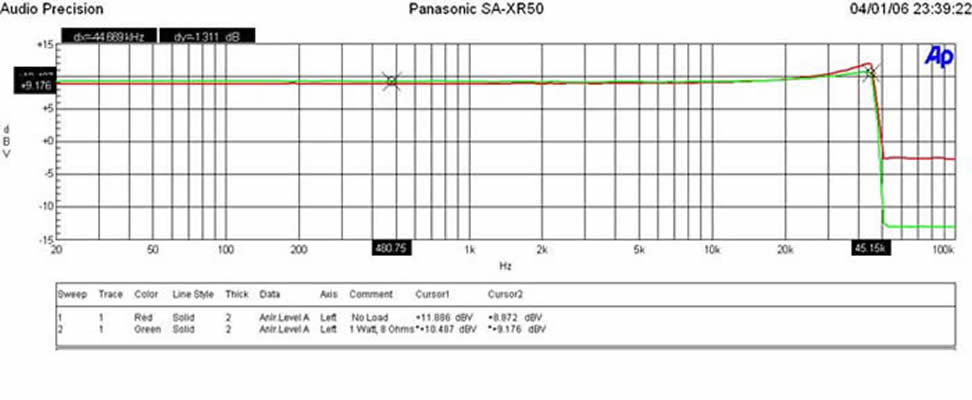
Panasonic SA-XR50 Frequency Response @ 2.83V
As you can see in the Frequency response graphs, out-of-band noise drops significantly once the amp is loaded with 8 ohms at 1 watt (green trace) , but a significant +3dB of overshoot is present at 40kHz in both loaded and unloaded conditions. AES17 20kHz filter was used during this test procedure.
Conclusion
Switching power amplifiers have a distinct advantage over linear power amplifiers in one particular area. They are far more efficient; this means that they don't require much of any heat sinking, they take up less space & weight, and most importantly, they are far and away much cheaper to manufacture than linear power amplifiers. In a market predominantly driven by price point, these types of units will continue to gain in popularity.
Audioholics would like to see switching amplifier performance improved in a few areas, such as reduced out-of-band components, lower output impedance, and most of all, improved grounding techniques.
While writing this article I am reminded of the classic truism of analog design: "Out of band rejection and noise reduction go hand in hand."
The designers say it doesn't apply here, but I have my reservations.
Dan Banquer would like to thank Mike Danielson of Sigma-Tel, Bruno Putzeys of Hypex, and Dick Pierce for their contributions to this article and they time they took to contribute to my education in this particular area. I am most grateful. An additional thanks to John Escallier for his editing.