
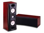
THIEL Audio MCS1, SCS3 and SS2 Loudspeaker System Review
- Product Name: THIEL Audio MCS1, SCS3 and SS2 Loudspeaker System
- Manufacturer: Thiel Audio
- Performance Rating:


- Value Rating:
- Review Date: August 30, 2004 19:00
- MSRP: $ 14,300
|
|
|
|
|
|
|
MCS1 |
SCS3 |
SS2 Subwoofer |
|
Bandwidth (-3dB) |
47 Hz-23 kHz |
46 Hz-22 kHz |
12 Hz - 300 Hz |
|
Amplitude response |
50 Hz-20 kHz ±2 dB |
48 Hz-20 kHz ±2 dB |
10 - 800 Hz ±3 dB |
|
Phase response |
minimum ±10° |
minimum ±10° |
N/A |
|
Sensitivity (dB) |
90 @ 2.8 V-1m |
87 dB @ 2.8 V-1m |
1 volt for 120 dB @ 1m |
|
Impedance (ohms) |
4 (3 ohms minimum) |
4 (3 ohms minimum) |
N/A |
|
Power |
-250 |
30-200 watts |
1000 Wrms |
|
Weight (lbs.) |
61 |
30 |
108 |
|
Price USD |
$2200 each |
$1400 each |
$4900 |
Pros
- Superb cabinet design
- Large selection of finishes and grill fabrics
- Grills can be left on for critical listening
- Overall Pleasing Sound
Cons
- Stands are not adjustable
- Limited low frequency response of main speakers
- Require higher than average current for optimum performance
MCS1, SCS3 and SS2 Company Background
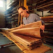
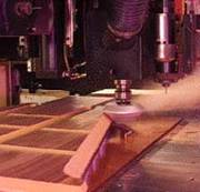
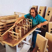
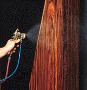
THIEL Audio Products Company of Lexington , Kentucky is a privately-held, engineering-driven organization that performs research, design, and manufacturing of loudspeakers. Their products incorporate a variety of unique technologies in driver design, acoustical construction techniques, and crossover design. Jim Thiel is a co-founder, co-owner, and product design engineer for THIEL. Jim pioneered the principle of time and phase accuracy in loudspeakers with the use of sloped baffles, coaxial driver mounting, and phase coherent crossover network design. Kathy Gornik, co-owner and President, is responsible for company vision, direction, policies, and marketing strategy. She oversees the appointment of all domestic dealers and international distributors, and is responsible for relations with the media and audio industry. THIEL Audio combines craftsmanship and unique technologies to manufacture each of their speakers. The process begins with careful selection of hardwood veneers from responsible foresters. The cabinets and finishes are machined with high precision CNC machining centers that provide tight tolerances and aid in creating their complex cabinet designs. The cabinets are then hand-assembled and finished to standards and procedures qualified for elegant furniture.
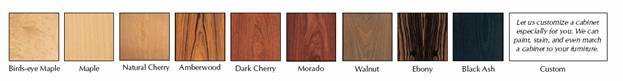
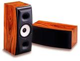
THIEL offers a broad range of finishes guaranteed to satisfy any tastes. They also offer custom finishes and optional grill cloth fabrics upon special request. Our review products were finished in dark Ebony, which wouldn't have been my first preference. I'd love to see them again in either Dark Cherry or Mocado both of which should certainly enhance the beauty of these cabinets.
Introduction
For many years I have revered the THIEL speaker cabinet designs and construction. Being a DIY speaker builder, I recognize their efforts on time alignment and minimization of diffraction which tends to be less common among the vast array of traditional speaker designs.
When I was asked by Audioholics Senior Staff if I wanted to review a THIEL speaker system, I received the news with enthusiasm and excitement, especially since I never had the chance to audition or closely examine their products before. I knew that by participating in such a review, I would now have the chance to thoroughly examine the quality of THIEL's loudspeakers. Once the necessary arrangements were finalized, the speakers were shipped in a matter of days and quickly integrated into Reference System 4. After my brief interlude, we later moved the system to our new Audioholics Interactive Home Theater (IHT) Center where we conducted our measurements and additional listening auditions with several of Audioholics Senior Staff.
Configuration and Setup
Our complete THIEL home theater speaker package included three MCS1 speakers for left-center-right, two SCS3 speakers for the surround channels and one SS2 subwoofer with Integrator controller. I first tried to set up the SCS3 surrounds on my current speaker shelves but they were a bit too heavy, implying that they were well constructed. Attempting to resolve this dilemma, we asked THIEL to send us their stands and within a few days we had the surrounds supported, set up and ready to audition.
The electrical connection for all speakers consisted of my all time favorite, easy to use design. The binding posts accepted dual banana plugs which made it especially easy to switch speakers during our comparative investigation.
After mounting the MSC1's to their respective stands, the combined weight made them a bit unmanageable for a reviewer working solo. I found that once these rock solid speakers were positioned, it's best to leave them be or if necessary, get someone to help reposition them later if required. The speakers were auditioned on Reference System 4 and IHT Reference System A (main system) thereby allowing us to do a more thorough audition.
THIEL MCS1 FRONT-LEFT-CENTER
-
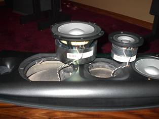
Drivers - 3-way system with 1" metal dome tweeter coaxially mounted in a 3.5" metal cone, short coil/long gap midrange; two metal cone, short coil/long gap woofers with copper pole sleeve and cast magnesium chassis; dual ported; magnetically shielded.
-
Bandwidth (-3dB): 47 Hz-23 kHz
-
Amplitude Response: 50 Hz-20 kHz ±2 dB
-
Phase Response: minimum ±10°
-
Sensitivity: 90 dB @ 2.8 V-1m
-
Impedance: 4 ohms (3 ohms minimum)
-
Recommended Power: 50 to 300 watts
-
Size (W x D x H):
-
Speaker Size 10 x 12.5 x 28.5 inches
-
Speaker on THIEL Vertical Stand Size: 13.25 x 17 x 39 inches
-
Speaker on THIEL Horizontal Stand Size: 31.5 x 17 x 20.75 inches
-
Weight: 61-lbs
For the MCS1s, THIEL provided two vertical stands for the left and right and one horizontal stand for the center speaker. These robust heavy weight black finished stands securely anchored the speakers in place by their sheer combined weight alone. The stands were supported by four spikes thereby maximizing decoupling from the floor. But with such a mighty decoupling stand, there tends to be some limitations with certain applications.
For
example, the horizontal stand placed the center speaker
quite low for my screen. Although it was angled upward
to make an attempt at aiming the acoustical axis toward
ear level, I would have preferred an adjustable height
stand so I could better govern the seating location.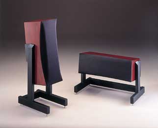
When setting up the MCS1's for left and right we had similar observations regarding their stands. When positioned out of the box, the tweeter was below ear level for my optimum seating position even though the speaker was angled upward. Perhaps adjustable stands would have provided a bit more flexibility in seating arrangement and speaker placement which otherwise seemed to be very constrictive. We asked Jim Thiel about the reasoning for such a design and his response was as noted:
“One aspect of the design of the MCS1 is that it is time coherent at (nearly) all radiation angles and therefore time coherence is provided regardless of the height or angle that the speaker is positioned. (This is an absolute technical requirement for all our non floor standing speakers.) Achieving this was a at the heart of the MCS1's design and is made possible by the fact of the speaker is a 3-way, and therefore the crossover point from the woofers can be low enough to preserve the "virtual woofer" performance through the operating range of the drivers.”
During installation in Reference System 4, I placed the MCS1 front and left speaker to the inside of my DIY reference speakers making them about 8 feet apart. The mains were positioned about 2 feet out from the front wall while the center speaker was against the front wall. The Integra Research RDC-7 was adjusted to compensate for the difference in distance between the main and center speakers from the listening position.
Editor Notes:
Placing the center speaker against the wall may have had two unintended consequences:
- Depending on how close the speaker was to the wall there would be a dip in approximately the 360Hz to 440Hz range. This range is critical for vocal intelligibility.
- Close wall proximity would also boost the frequencies below 360Hz possibly adding an chestiness to the vocals.
Ken states that his screen is mounted fairly high on his wall. So placing the left, right and center in vertical orientation (and moving the center more forward, away from the wall) should yield ideal lateral sound pans with matched-timbre spectral balance.
MCS1, SCS3 and SS2 Speaker Design
The
stands for the SCS3 surround speakers happened to
be placed at ear level for the lower front seats.
I set them up near the corners at the back of the
room and towed them slightly inwards. 
Another commendable design concept from THIEL Audio was the implementation of large radius curves located on the front baffels of the MCS1s and the SCS3s. I once read in one of my speaker design books that small radius curves on a front baffle has insignificant impact to the tonal quality of the speaker however a large radius of about 4 inches can actually help reduce the diffraction from the edge of the cabinets for mid and high frequencies. THIEL Audio has been applying this design concept to their designs at least as long as I have known about the company. Since the MCS1 is a MTM (midrange-tweeter-midrange) design it is quite difficult to keep a large radius curve on the front. To solve this physical limitation, THIEL created moon shaped sides resulting in a larger radius near the drivers along with a 3-inch thick front baffle.
The thick front baffle combined with 1 inch thick side and back panels and excellent shelf-type bracing all made from MDF (medium density fiberboard) make this cabinet solid and formidable.
Giving
the speaker a simple but revealing knuckle revealed
that none of the panels showed signs of drumming or
vibration. Having no cabinet vibration is crucial
as to not color the sound during playback and THIEL
seems to have taken care of this problem quite well.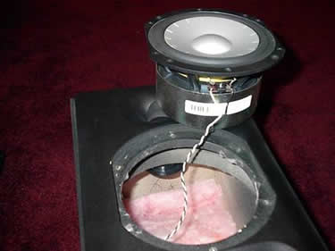
The mid/tweeter chamber was completely sealed although I could not see what material was used for this sub-enclosure. We had several technical questions which we posed to Jim Thiel including this about the sub-enclosure:
"The walls of the mid/tweeter's sub-enclosure are made of a round tube of compressed paper that is a little more than a quarter inch thick. The round cross sectional shape gives this enclosure very high strength and non-resonant behavior."
One setup tip we learned was that THIEL recommends leaving the large allen head mounting screws installed if the MCS1s are not mounted to their stands since the threaded holes go all the way through the cabinet. If the four holes are left open then, the back pressure from the woofers will travel through these holes which may result in whistling noises.
There are only a few companies that I'm aware of that go the extra mile when it comes to mounting the drivers, and THIEL has been inaugurated as one of them. Unlike the mainstream wood screws in MDF, all of THIEL's drivers were mounted with machine threaded screws into metal threaded inserts. Most folks who do not review or dissect speakers will likely not notice this feature. My opinion is that the benefits of using threaded inserts exceed the extra manufacturing costs as it ensures the best possible rigid mounting of the driver to the cabinet. Plus, as someone who loves to dissect speakers, I found that the allen head screws helped reduce slippage when tightening or loosening them. I tend to be very cautious when using a phillips head since I always feel that I'm going to slip and go right through the cone. Thus we don't recommend doing this at home. As an added bonus, the screws were all gold plated. But when removing the grills, I thought the gold screws created too many different colors on the baffle. However, the gold screws do reveal a behind the scenes peak at how THIEL Audio paid attention to every detail.
One surprise we noticed during our investigation was that there was no damping material on the side walls of the cabinet and no gasket was used under the drivers to seal them. The only other cabinet we've seen that didn't have these features included the Canton Karat Reference 2 DC speakers which we reviewed several months earlier.
I found it peculiar how THIEL Audio recessed the drivers. The mid/tweeter driver had a conical shape to the frame as opposed to a more common flat shape. It was recessed about 3/4 of an inch with the cabinet continuing the same slope as the driver. I thought that the purpose of this was to line up the voice coil to the woofers so that the time coherence was maintained. I quickly noticed that the woofer was also recessed about 3/4 of an inch which seemed to misalign the voice coil thereby seemingly negating the time coherence. We asked Jim Thiel the reasoning behind such a design and he responded with the following memo.
“You are perfectly correct that "the recessing of the tweeter is to line up the voice coils for the purpose of time alignment". You are also correct that if we did not recess the tweeter there would be a little bit of diffraction eliminated. And, further, you are also correct in noting that if we did not recess the woofers we would not need to recess the tweeter to achieve alignment. With most drivers this would not be true. It would usually be that if none of the drivers were recessed they would be far from time-aligned because the woofer's coil would normally be much farther behind the baffle than the tweeter's. Why it is true with the MCS1 is because both the woofer and tweeter are unusual in their geometry. The tweeter has a built-in recess from the geometry of its chassis that places the midrange cone rim behind the baffle surface and the woofer has an extremely shallow diaphragm geometry that is made possible by the use of a thick, cast polystyrene foam layer laminated behind the aluminum layer of the diaphragm to obtain the required strength and stiffness. So, why did we not utilize these features as sufficient to achieve correct time-alignment and mount the drivers without any recess? Good question! The answer is that the woofer would actually not have its minimum diffraction mounted flush with the baffle.
This is because the surround itself is usually a source of significant diffraction because it protrudes in front of both the diaphragm rim and the baffle. What we have done instead is to design the two-layer diaphragm with enough thickness at its rim so that, by mounting the surround from behind the diaphragm, the surround's roll creates a (relatively) smooth continuation of the diaphragm's shape, rather than an abrupt protrusion.
To complete the desirable situation of a smooth shape from diaphragm to surround roll and on to the baffle, we have recessed the driver chassis enough so that, with the use of the ring, there is no significant, abrupt change from the surround roll to the baffle. So all this was done to reduce diffraction from the woofers' surrounds, with considerable measured success. Now, it is true, as you say, that this woofer diaphragm / surround design and driver mounting requires that we recess the tweeter. But the extra recess is only about 1/4 inch and by being very careful with the shape of the recess there is very little added diffraction from the tweeter. You notice that the recess does not continue from the tweeter chassis's edge but rather has a different size and shape that was found to produce less diffraction.”
In summary, it seemed that Jim Thiel indicated that the woofer was first recessed and then a ring was mounted to the top of the driver's frame so that any diffraction from the driver piston to the surround material can be properly eliminated. In other words the ring keeps a smooth transition from the cone to the extent of the front baffle. The woofers has a shallow cone which allows for a low mass piston but materials are added to stiffen the cone to make it more rigid. The shallow cone allows its voice coil to be more forward than most woofers. Now, the conical shape of the mid/tweeter frame itself causes the voice coil to be farther back than a tweeter with a flat frame which allows alignment of the mid/tweeter and woofer voice coils. This shape is merged with the front baffle so that there are no abrupt changes in the surface from the actual moving piston to the extent of the baffle, just like the woofers.
So the recessing is to eliminate diffraction and the shapes of the drivers allow time alignment. Mr. Thiel pointed me to their that one of their technical white papers explains this concept in more detail.
One of the most unique things I've seen with their speakers is Jim Thiel's design of the coaxial driver. As shown below there is a dome tweeter and a cone midrange that share one voice coil with some material used to couple the two together. The purpose is to have time coherence between the mid and high frequencies by eliminating the phase problems exhibited by an electronic crossover circuit. It seems that there would be some lag caused by the coupling suspension.
Pictorial representation of the THIEL Coaxial
Driver
Think of holding a spring with a weight on the other end. As you move your hand up and down slowly the weight moves along with your hand at the same speed but as you increase the speed of your hand motion the motion of the weight can't keep up with the motion of your hand because of its mass; the weight lags the motion of your hand. The same theory seems to apply here, the dome should have less mass than the cone portion and the so called spring is the coupling suspension; therefore the midrange cone would seem to lag the movement of the tweeter dome. According to Thiel, there isn't any lag, and here is his commentary on this topic:
“There is no time lag between the mid and tweeter since they are driven by the same voice coil.
There is phase shift but this is opposite for the two diaphragms and cancel out in the speaker's total output. This is also how a first order crossover works; there is phase shift but it is equal and opposite and less than 180 degrees and so can be made to perfectly cancel in the acoustic output.”
We also asked how the crossover occurs between the dome and the cone of this driver and this is what Thiel had to say:
“How the mechanical crossover works is that the coupling suspension's stiffness is high enough so that at low frequencies the two diaphragms move together as one unit. So the tweeter diaphragm is contributing to the low frequency output but at a much reduced level. At high frequencies the coupling's compliance allows the midrange diaphragm to "decouple" from the voice coil because high frequency force cannot be conducted through this compliance to the relatively heavier midrange moving system. So at these high frequencies the tweeter diaphragm is the only one driven by the voice coil, since it is directly connected.”
This explanation is a much better answer for both the time lag and crossover questions. It seems Mr. Thiel is saying that at the lower frequencies (slower speeds) the dome has such a low output you can't hear it but at the higher frequencies (faster speeds) the coupling suspension (spring) does not allow these frequencies through so the cone would not lag nor play the higher frequencies hence there is a mechanical crossover.
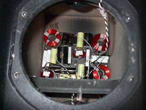
The SS2 subwoofer didn't raise nearly as many questions since it had a more traditional truncated cast frame and an aluminum cone with rubber surround. I also found the crossover quite interesting since all of the components were wired by their leads. In other words there was no printed circuit board and no wires connecting component to component thereby minimizing connection paths. All internal wiring used 18 AWG solid twisted pair. THIEL's logic behind the Speaker Wire can be found in our FAQ with Jim Thiel which is included at on Page 8 of this article.
|
|
|
|
Notice the cast baskets and large motor structures of the drivers. |
Notice the quality air core inductors, polypropylene capacitors and ceramic resistors. |
MCS1, SCS3 and SS2 Design and Setup
THIEL MCS1 Front Grill
Prior to my audition, I curiously explored the sleek, tightly fit speaker grills. Upon thorough investigation I noticed that they were very difficult to remove. Once I managed to pry them off, I recognized that the grill frame was constructed with a semi-flexible aluminum frame that is made to slide very firmly around the front of the speaker. Once wedged back on, I discovered why the grill cloth draped tightly around the front baffle. This method minimizes diffraction caused by the speaker grill thereby allowing purists to leave the grill on during their critical listening. The THIEL grill design is commendable.
THIEL SS2 (formally called SW1) Subwoofer
- Powered subwoofer with two 10" metal cones
- Short coil/long gap woofers with 2.5" diameter voice coils
- copper pole sleeves
- 20-pound magnet structures
- high excursion suspensions
- cast aluminum chassis
- optional companion SC1 Controller
Thiel SS2 Subwoofer Amplifier Specifications:
- Type: Switching, Class D
- Power: 1000 watts, RMS
- Distortion: less than 1% at full rated output.
- 16 Hz-800 Hz
- 17 Hz–300 Hz ± .5dB
- 1 volt for 120 dB@1m
- 11 x 20 x 23.5 inches
- 108 pounds
- 10 years
Subwoofer "The Integrator" Controller
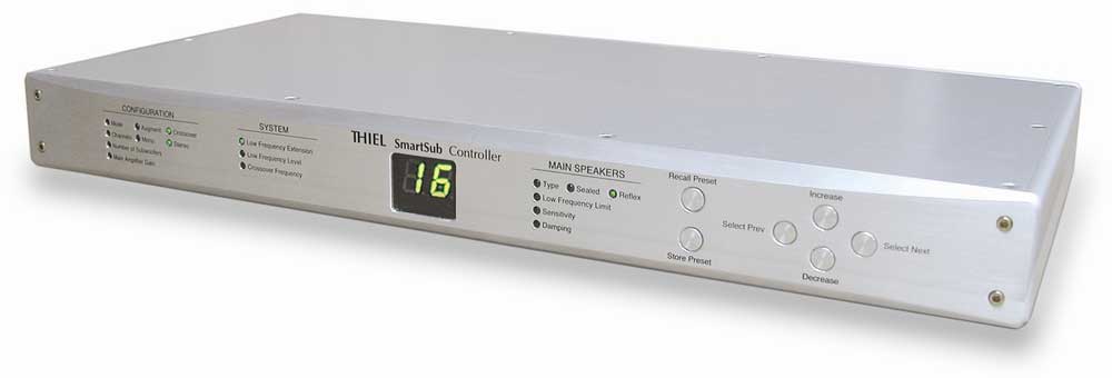
THIEL Audio's "Integrator" subwoofer controller offered several unique adjustments as part of THIEL's all digitally controlled SmartSub technology. There were three buttons located on the front panel of the controller. One was devoted to mode select button and the others were for increasing and decreasing the settings. The mode selections included an output level setting along with rather unique, side and rear wall settings. The wall settings could be configured with distance settings from the side wall and rear wall.
According to Jim Thiel:
“…the settings actually alter the frequency response of the subwoofer to compensate for the frequency response changes caused by the reinforcement and reflection of the nearby wall. This compensation allows the energy put into the room to be essentially the same as it would be without the nearby walls rather than being greatly altered by the wall effects.”
Editor Notes:This form of boundary compensation is usually found on bi-amplified 6” or 8” two-way studio monitors. The compensation usually has a “shelving” characteristic which means that it affects all frequencies from a certain point down(i.e. 80Hz). The reason to do this in a two-way studio monitor is to prevent excessive bass boost which would tend to color the vocals, and frequencies typically below 2KHz, which are handled by the woofer in these bi-amped designs. To apply this logic to a subwoofer means that you are abdicating substantial amounts of “free” boundary proximity gain and asking the woofers themselves to perform all the bass duty. Granted, the substantial “free gain” of common subwoofers often leads to a peak at some frequency below 100Hz but there are several subwoofer systems on the market today which incorporate at least a single band of parametric equalization which allows the system's response to be relatively flat while in a corner and still enjoying the benefits of passive, free room gain.
SS2 Subwoofer Setup
Given the layout of the theater room and my personal tastes, I did not position the SS2 subwoofer as suggested in the owner's manual. Instead, I located it in the back of the room remembering that bass is non-directional and that it shouldn't matter which corner it is placed so long as I accurately compensated for path differences between the speakers and subwoofer via the processor digital delay settings.
One feature the SS2 didn't offer was a frequency setting; but when considering that most current processors or receivers include adjustable LFE output, leaving out this feature seemed more intentional than an oversight. Depending on your particular configuration, the SW1 can be hooked up to a system without an LFE output via THIEL's separate controller or a passive crossover to match any main speaker.
One minor note about the SS2 subwoofer that I noticed was that the power indicating LED was placed on the front baffle making it visible during movie watching. At first I found this to be a nuisance as the LED was distracting in the dark. It was only by further investigation and questioning this feature directly with THIEL Audio that I was able to find that the LED can indeed be turned off by pressing both the "increase" and "decrease" buttons at the same time which to me seemed a rather odd procedure.
MCS1, SCS3 and SS2 Measurements and Analysis
We concluded our audition with measurements of the MCS1 and SCS3 speakers. The results of the measurements are in correlation with our listening audition thereby allowing us to provide subjetive and objective feedback on the THIEL Audio Speaker System.
Measurements
& Analysis of Thiel MCS1 Speakers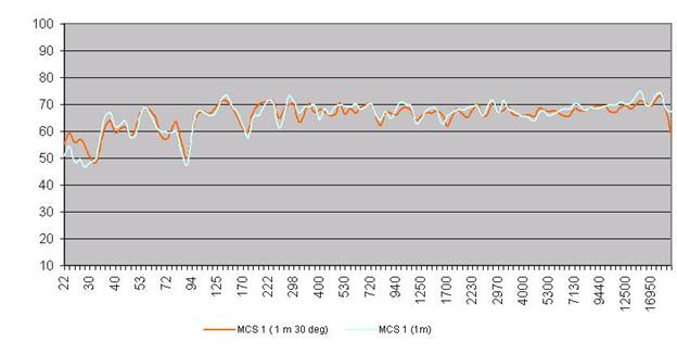
The MCS 1 had an overall uniform frequency response with a slight de-emphasis (-5dB from 3kHz to 7kHz) and a tad too much emphasis on the top end (+5dB above 13kHz ) with a -3dB roll off around 20kHz. The null at 89Hz is likely due to measurement/room interaction since this was not taken in an anechoic chamber. Off axis response was excellent and did help tame the top end a bit indicating that little to no toe in is preferred for a more flat frequency response. Usable bass energy was present to about 38Hz or so, but we still recommend crossing over these speakers much higher (say 80Hz) to increase system dynamic range and provide better bass integration with the subwoofer.
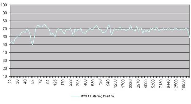
Notice the 89Hz null is gone at the listening position (3 meters) indicating it was likely do to measurement/room interaction rather than loudspeaker design deficiency.
This measurement was taken with the MCS1s set to full range with no subwoofer. The suckout at 50Hz is again likely a room node issue relative to speaker/listener placement. By crossing these speakers over and optimally placing the sub, much better bass integration and extension was achieved.
Measurements & Analysis of Thiel SCS3 Speakers
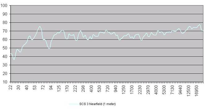
The SCS3 had an overall fairly flat response as well (similar to the MCS1) except the tweeter was again set too high (up to +7dB from 12kHz to 18kHz) with excellent extension past 20kHz. Again we see the same 89Hz suckout due to measurement/room interaction. The SCS3 had usable bass extension down to about 44Hz, but we again advise to cross this speaker over much higher to preserve dynamic range, especially since we found this speaker a bit lacking in this regard.
Q&A; with Jim Thiel on Internal Wiring of Speakers
During our review of the THIEL Audio SCS3 system, we pinged designer Jim Thiel on some technical questions regarding the loudspeaker designs and the choice of internal wiring and crossover topologies he employed in the speaker designs. With his permission, we captured the interview which oddly focused more on the topic of cables than it did loudspeakers as can be seen below.
Italics = Jim Thiel's commentary and responses
Normal text = Audioholics Responses
Jim Thiel:
For
the internal wiring we use a custom-made wire that
is a solid, 18 gauge, oxygen-free, Teflon insulated,
twisted pair that I think sounds best and I will try
to explain why by first explaining some things about
amplifier cable. It is necessary that amplifier cable
have very low electrical resistance for two reasons.
The first is that any resistance will cause a loss
of power, the degree of which is determined by the
impedance of the speaker. If a speaker has lower impedance
then the cable's resistance will be a higher proportion
to it and therefore "use" a higher proportion
of the amplifier's total power.
Audioholics:
I
agree cable resistance is paramount and should be
kept minimum. That being the case, why not use a lower
gauge wire, say 10AWG to further reduce DCR? I don't
think it will matter much for a few feet of internal
wiring, but since you make a case for it, please refer
to the AWG Table below. This
is for Solid Core Wire, Stranded wire is slightly
less because of higher cross sectional area.
Note that 18AWG wire has over 6 times the DC resistance of 10AWG. Thus for amplifier cable runs of say 20ft of 10AWG wire (not considering LC losses) we have about 40mohms of DC resistive losses (below 50kHz - as AC resistance does double due to Skin effect), thus total loss across a 4 ohm load would be 20*log(4/(4+.04)) = .086dB - hardly significant.
Jim Thiel:
I
am afraid I was not sufficiently clear. In the
above
I was first explaining some things about amplifier
(-to-speaker) cable, as contrasted to speaker
(internal)
wiring. I was discussing the importance of low
DCR in amplifier cable so that when I later explained
why very low DCR is not required in our speakers
it
would not be thought that I was making that claim
for amplifier cable. (For
example, if the cable has 4 ohms of resistance)
Audioholics:
What
cable has 4 ohms of resistance? Even 20ft of 18AWG
only has 260mohms of resistance!
Jim Thiel:
Of
course no cable has 4 ohms resistance. It is just
a convenient value to use for illustration. and
the speaker has 4 ohms of impedance, then the cable
would use up half the amplifier power.) Now, in practice,
a bigger problem than the loss of power, which is
usually not more than 1 dB, is that since the speaker's
impedance is (maybe quite) different at different
frequencies, the power used up by the cable will be
different at different frequencies. This causes the
frequency response from the speaker to be altered
by the cable's resistance, with very little reduction
at frequencies that have high impedance and greater
loss at frequencies where the speaker's impedance
is low.
Audioholics:
True
but again even the few feet of 18AWG wire internal
in your speakers adds about 40mohms of resistance.
If the driver impedance low point is 4 ohms, this
represents 20*log(4/4+.040) = .086dB add that to the
20ft of 10AWG speaker cable and you get about .17dB
of resistive losses which are still insignificant
and really not worthy of debate.
Jim Thiel:
Well,
you may be right that .17dB is insignificant.
I do
however believe that even this small amount of inaccuracy
is audible under some circumstances and in fact
I
spend a great deal of engineering development time
reducing response errors that are of this degree.
(By the way, this is one of the reasons we use additional components in our crossover networks which are not in the signal path but are for the purpose of evening out the impedance so that cable losses will be uniform at all frequencies and the response will not be altered even if the cable's resistance is significant.)
Audioholics:
This
is an interesting goal, one that would certainly be
advantageous when using high resistance exotic speaker
cables. I would like to see how this works if you
would so kindly share a schematic for it.
Jim Thiel:
The
sub circuits added are usually one or two of either
a series connected capacitor and resistor or a series
connected capacitor, inductor and resistor. These
series circuits are added across the input terminals,
in parallel with the speaker. The first circuit can
correct an impedance that rises at high frequencies
and the second can correct a hump in the impedance.
Audioholics:
What
you are describing here is a classic Zobel network
usually used to flatten out impedance of a speaker
to counter the rising impedance of a tweeter voice
coil, or in some cases to restore amplifier phase
margin and increase stability for heavy reactive loading
due to an exotic cable or complex impedance of a speakers
crossover. This is a fairly standard practice but
I fail to see how this will uniformly counter resistive
losses due to cabling. My advice here, if you think
it is of concern, is to use heavier gauge wire internally
in the speaker cabinets and recommend consumers to
use heavy gauge speaker cabling (say 10-12AWG).
Jim Thiel:
The
second reason amplifier cable resistance needs to
be low is to avoid significant intermodulation. Intermodulation
is when the signal to the woofer affects the signal
to the tweeter, or vice-versa. Since current that
will be directed to the woofer by the crossover network
will cause a loss in the cable by its resistance,
the tweeter will "see" this reduced input
also. So at frequencies that are reproduced by both
drivers, there will be distortion produced in one
driver by the current used by the other driver.
Audioholics:
Again
I don't see how cable resistance in a decent 10AWG
speaker cable would be detrimental. What you seem
to be describing is back EMF, which can be more problematic
with series crossovers than with parallel networks,
see:
Series vs Parallel Crossover Types
Jim Thiel:
Well,
again, I agree that this will not be a problem with
amplifier cable of sufficiently low resistance. And
again I am just explaining why amplifier cable resistance
needs to be low; why, say, 4 ohms is not sufficiently
low.
So for both these reasons we need amplifier cable to have low resistance and the most straightforward way to get low resistance is to use a large gauge wire, but this causes a practical problem in that the wire gets very stiff and unbendable. Therefore stranded wire is used but this causes sonic problems because the current will pass from strand to strand and encounter non-linear, distortion producing extra resistance.
Audioholics:
Non
linear distortion in a cable? We haven't found this
to be true after extensive testing and calculations.
This has been an unfortunate fallacy promoted by many
exotic cable vendors for years, whom incidentally
offer no measurable or analytical proof to justify
these types of claims. I realize Thiel supports many
high end dealers who sell exotic cables that market
this fictitious claim, but you may wish to reconsider
making such a declarative statement about this, especially
in light of the inarguable proofs we offer rebuking
this in the following articles:
How does strand interaction produce extra resistance? I don't understand.
We realize many exotic cable vendors buy solid core wire in bulk from manufacturers such as Belden and therefore attempt to rationalize its superiority by introducing pseudo sciences, but please realize over the past two years we have written extensive articles about cables, while demystifying many of the snake oil claims.
Please see: Cable articles
As a result, consumer awareness about cable snake oil is at an all time high. It would serve all manufacturers best interests to be more objective about cables and not support baseless claims to server dealer sales of exotic cabling. We have nothing against solid core wire, or expensive cables for that matter, providing that the manufacturer claims aren't without merit. As a result, many legitimate cable vendors advertise on our site and others have even updated their literature to be more factual-based on provable cable theory.
Please note our contributing staff (in addition to myself) includes a list of field experts such as Dr. Howard Johnson, Henry Ott and engineers from Wayne Kerr - a Leading Test Equipment Manufacturer
Jim Thiel:
A
"fix" for this is to separately insulate
each strand but then you can have the problems caused
by poor dielectrics (insulators) since good dielectrics
cannot be made very thin.
Audioholics:
What
defines a good/poor dielectric for speaker cables?
You may wish to review our article on this topic.
Other than serving the role of insulation and controlling
cable capacitance,cable dielectrics really serve no
other role on speaker cables, which will influence
measurements or sonics.
Jim Thiel:
I
agree that much of the promotional claims about amplifier
cable is baseless and/or misleading and also that
much high end cable is overpriced (sometimes drastically)
in terms of performance. However, I believe that some
cables do have detrimental effects on sound quality
that are not explainable by resistance or inductance.
Whether these almost always subtle distortions are
caused by dielectrics, oxidation, bi-metal plating,
etc are not determinable by me. But of course that
something cannot be proved doesn't mean it does not
exist.
Audioholics:
Again
I encourage you to review the article we authored
on cable distortion. It clearly demonstrates there
is no mechanism responsible for causing non linear
distortions in wires. If there were, don't you think
a credible source such as IEEE or experts in Electronics
Fields and Waves experts would have authored a paper
on this? The only folks touting cable distortion are
exotic cable manufacturers and supplementary cable
forum cult hobbyists.
Jim Thiel:
So,
with this background, we come to internal speaker
wire. What we do is, first, internally bi- or tri-
wire all our speakers. This means that we have completely
isolated the electrical current in the woofer circuit
from that of the tweeter; there are no wires, even
ground wires, in common between drivers, beginning
right at the input terminals. The benefit of this
isolation is that there cannot be any intermodulation,
no matter how high the resistance of the internal
wiring is. The next thing is to realize that, since
we have eliminated intermodulation as a problem, low
wire resistance is no longer necessary at all because
the losses caused by resistance of the short lengths
of internal wire is low and because any such losses
can be corrected by adjusting other elements of the
speaker's design, like crossover component values,
driver magnet size, etc. In other words, we can engineer
the speaker to have the correct response taking into
consideration the small amount of resistance of the
internal wiring.
But why would we bother having to take this into account? Why not just use larger, stranded wire? The reason is that by using smallish solid wire we can completely eliminate any distortions produced by stranding and/ or their insulation.
Audioholics:
Again
you may wish to reconsider this viewpoint since it
lacks any scientific proof, merit or credibility.
There is no proven distortion mechanism for wires.
Using the best test gear on the market (Audio Precision
2) we have demonstrated no nonlinear mechanism exists
for this to occur. If it did, how would engineers
design sensitive test equipment, space probes etc
if their wires were causing so much distortion? Even
if measurable wire distortion did exist, it would
not even be a 1/100 th of the magnitude of distortion
induced by the drivers or circuit components. Wouldn't
you agree?
Jim Thiel:
Yes,
I would agree that wire distortion would be 40 dB
lower than usual driver distortion. (But we have reduced
that by a factor of 10 also.) But even so this would
not ensure that such distortion was inaudible. I don't
care much if something is proven or not since my solution
is of low cost. As I mentioned earlier I do believe
there are sonic effects that I don't know how to measure
and since I can eliminate this possibility for very
little cost, I don't see why I would not do so.
Audioholics:
Wire
distortion 40dB lower than driver distortion!?!
That's
news to me. If this were true surely a simple
measurement would demonstrate this. Again I defer
you to an article
we already conducted thorough testing of wire
distortion for a wide assortment of cables and
found nothing.
Cable Distortion
Let's figure a usual driver distortion of 1% or -40dB. If we look -40dB lower than that for cable distortion, we would need a resolution of -80dB. Please note that the accuracy of our test contained resolution of greater than -120dB (.0001%) or over 100 times more precision than required, and certainly more resolution than even the best audio systems could provide, yet no presence of wire distortion was found.
Jim Thiel:
We
need only one layer of insulation which can be of
the best type, Teflon, without worry that the thickness
of the insulation will be a practical problem. So
we can choose the best sounding wire, which is smallish
solid wire, without having to accept any compromises
caused by (a little) higher resistance.
Audioholics:
Again
I don't see how you can conclude the "best sounding"
wire for a few feet of internal cabling of even the
worst (18AWG wire). I assume this is merely a statement
of opinion.
Jim Thiel:
Well,
I have tried to explain why, in our speakers, even
ten ohms of internal resistance would not cause any
sonic problems other than sensitivity loss, how we
wire our speakers to eliminate the possibility of
other subtle factors having a negative effect on the
sound, and how we can achieve our objectives without
spending a lot of money that I feel is better spent
on better drivers or cabinet.
Audioholics:
Ok
so what you are saying is that the consumer can use
any type of wire, stranded or solid core, 10AWG or
22AWG and still expect excellent performance with
perhaps some loss in sensitivity when higher gauge
wires are used. So why are we having such an involved
discussion on wires? :-)
Jim Thiel:
Well,
this had been a very long answer, and probably more
than you wanted to know, but I hope it answers your
question.
Sincerely,
Jim Thiel
MCS1, SCS3 and SS2 Listening Tests and Conclusion
I find it important to do a 2 channel audition of the main speakers prior to evaluating the entire speaker system as a whole. My experience has been that if the main speakers perform commendably as mains then they will most likely sound equally as good when combined with the rest of the package for multi-channel. After listening to the main speakers solo, I initiated the sub to create additional bass and continued my audition. Once I was satisfied with this combination, I finally moved on to the entire speaker system.
 Starting
with a Yes CD titled, "The Ladder" I
noticed right off that the THIEL MSC1s had that
involving character this CD portrays. Jon Anderson's
voice was nicely forward and the pace was good,
probably due to the rigid aluminum drivers. When
I got to “Lightening Strikes” I turned up the volume,
but no louder than I normally listen. It was this
point that I started to hear some edginess and
harshness typical of hard dome drivers. While most
won't notice such a sound character, my ears seem
to be extra sensitive to this tonal unbalance.
Perhaps this edginess could be a result of the
way the tweeter was recessed but it's hard to say
for certain what may be the cause.
Starting
with a Yes CD titled, "The Ladder" I
noticed right off that the THIEL MSC1s had that
involving character this CD portrays. Jon Anderson's
voice was nicely forward and the pace was good,
probably due to the rigid aluminum drivers. When
I got to “Lightening Strikes” I turned up the volume,
but no louder than I normally listen. It was this
point that I started to hear some edginess and
harshness typical of hard dome drivers. While most
won't notice such a sound character, my ears seem
to be extra sensitive to this tonal unbalance.
Perhaps this edginess could be a result of the
way the tweeter was recessed but it's hard to say
for certain what may be the cause.
Next up in my audition was Enya's “Shepard's Moon” CD which I mainly use to determine transparency. The MCS1's had a very open wispy air sound that made me forget the speakers were producing the sound. During my entrenchment in this CD on the THIEL MCS1 speakers, they did an effective job of becoming transparent. On “Marble Halls,” I also listen for the detail in Enya's voice. I could hear the sibilance of her “S's” quite well and I could hear every breath she took though the distinctiveness tended to be merged with the overall sound.
I then switched to Flim and the BB's “Big Notes” CD which is proves to be better CD for evaluating detail. During the “New America” track, I did notice the sufficient detail I anticipated and the tonal balance was quite good on these speakers. The low end wasn't boomy and they were not overly bright but seemed a bit lacking compared to other speakers I auditioned on my Reference System.
On “Malcolm Makes Haaj” the sax solo had sufficient realism and placement enough that I could imagine the sax player standing on stage, belting out the song. The drums in the drum solo sounded just as real as the sax and compared to my DIY reference speakers in some aspects, it sounded even better. The trumpet solo also sounded real and natural with just a tad bit of edginess which can be indicative of this solo on many other speaker systems.
Patrick O'Hearn's “Trust” CD is what I use for the bass test. Although the MCS1 speakers are only rated down to 50Hz, they did a good job of reproducing adequate bass. But as expected, the low bass was lacking thereby justifying the need for the THIEL SS2 Subwoofer. Given the capabilities and performance of the MCS1 speakers, we recommend setting the subwoofer cut off frequency to 80-Hz which happens to be inline with THX's recommended configuration. Once it was initiated, SS2 subwoofer did exactly what it was supposed to do. It seamlessly added the deep bass extension that was missing from the MCS1's alone. Even though the sub was at the back of my room, I could not tell where the extra bass was coming from. The low end wasn't boomy or too punchy. It was just good deep musical bass making it a definite compliment to the MCS1's.
During additional vocal tests I played Suzanne Vega's “Tom's Diner.” Her voice was very centered and the sound stage was high but I didn't get the sense that she was standing there. On Into the “West from Return of the King” by Annie Lennox's, her vocals were also centered and forward but not succinct. The treble seemed a little too edgy and harsh compared to other speakers I've heard. I completed my two channel audition with Steely Dan's “Two Against Nature.” Aside from the sax sounding a bit too aggressive, Fagan's voice was plenty forward and well balanced. The overall sound was full with good authoritative bass complimented by the SS2 subwoofer.
Movie Listening
Upon completion of my two channel audition, I perused through several movie tracks in full multichannel as I implemented the entire THIEL Audio speaker package. The main things I look for in movie playing are: could I understand the dialog, was the music in the movie involving, are the low frequency effects involving, and is the sound panning believable (i.e. images and sound moving left to right and front to back). One really great movie for testing an AV system is “Finding Nemo”, not only is the video quality excellent but so is the sound. The mine explosion scene in this movie is some of the most taxing effects on a subwoofer I've heard. The SS2 THIEL Audio subwoofer did a commendable job in reproducing the gut wrenching bass found in this scene. Though I found it didn't quite have the punch of my reference subwoofer and I did think I detected some minor distortion when pushed to louder volume levels during this specific track, I did not hear any additional significant distortion during other movies. The SS2 with Integrator controller coupled with the MCS1s proved to work sufficiently for movies and music tracks. On some of the loud volume action scenes when there was dialog, effects, and music all playing together, I could again hear the hardness of the treble but other than that I really enjoyed the whole set of speakers for movie watching.
For dialog the MCS1 as a center speaker did a standing job. I could understand the dialog clearly on most scenes though there seemed to be some times where I didn't hear quite as much clarity as anticipated. This may have been a result of the liveliness of my room. Due to the difference in height between the center speaker and my screen sometimes the dialog didn't appear to come from the characters. This type of audio deficiency was one of the very reasons why I would have preferred an adjustable height speaker stand as it would have allowed me to aim the MCS1 to a more optimal playing position.
For fun, I conducted some two channel listening with the SCS3s where I later found them to not seem well suited for such a task. I noticed that as I turned the volume up, the SCS3s seemed to be compressing the sound which we later verified during our measurements. Thus in my opinion, the THIEL SCS3 surround speakers served best for surround effects as opposed to bookshelf two channel listening.
When implemented as surround speakers, the SCS3s participated adequately in their intened role. All of the movement from front to back sounded very smooth and there was no change in tonality. Also, as expected since the front three speakers were identical, the movement across the front of the screen was very seamless. Almost everyone likes the THX introductions that come with movies mixed in THX. When the THX intro was played back on the THIEL Audio speaker package, it was as impressive as always.
Conclusion
Much of what we discussed during our audition is well supplemented in our farfield and nearfield measurement plots found on page 7. Overall the MCS1-SCS3-SS2 home theater speaker system offered a standing performance especially considering that it is an entry level system from THIEL. THIEL offers excellent build quality, craftsmanship, and high quality speaker systems along with excellent fit and finish, high product appeal, and the added bonus of a well balanced soundstage. Hopefully we will get a chance to audition some of their higher end speakers in the future.
The Score Card
The scoring below is based on each piece of equipment doing the duty it is designed for. The numbers are weighed heavily with respect to the individual cost of each unit, thus giving a rating roughly equal to:
Performance × Price Factor/Value = Rating
Audioholics.com note: The ratings indicated below are based on subjective listening and objective testing of the product in question. The rating scale is based on performance/value ratio. If you notice better performing products in future reviews that have lower numbers in certain areas, be aware that the value factor is most likely the culprit. Other Audioholics reviewers may rate products solely based on performance, and each reviewer has his/her own system for ratings.
Audioholics Rating Scale
 — Excellent
- — Very Good
- — Good
- — Fair
- — Poor
| Metric | Rating |
|---|---|
| Build Quality | |
| Appearance | |
| Treble Extension | |
| Treble Smoothness | |
| Midrange Accuracy | |
| Bass Extension | |
| Bass Accuracy | |
| Imaging | |
| Soundstage | |
| Dynamic Range | |
| Performance | |
| Value |
Ken Stein is a contributing writer and reviewer for Audioholics and he really REALLY likes his speakers (which he should, since he spent countless hours hand-crafting them himself.) Ken is an engineer with FedEx and applies his diligent attention to detail to his speaker and electronics reviews here at Audioholics.
View full profile