
Myths & Facts about Loudspeaker Crossovers: Identifying Legitimately High Fidelity Designs
Crossover Filter Types
This article explores some of the myths and facts about crossover design. It also discusses some of the mistakes often made by loudspeaker manufacturers done either as cost savings or design incompetence. It is our hope that the reader will gain a better understanding of the mechanics of loudspeaker crossovers so they can make a more informed purchasing decision.
The loudspeaker crossover can be considered the brain of the loudspeaker. It directs the bandwidth of frequencies each driver is optimized to reproduce while it also level matches each driver and can help to stabilize the load impedance the amplifier will see. Without the loudspeaker crossover, a loudspeaker driver such as a tweeter can be overdriven which can lead to distortion and eventual failure. A loudspeaker system without a properly designed crossover (or none at all) can cause too much frequency overlap between drivers which can increase distortion and degrade overall sound quality.
Properly designing a loudspeaker crossover requires engineering talent and sufficient budgeting to fit it into the total system cost. There are often times manufacturers will downplay the crossover’s importance, either because they lack the knowledge to truly understand its role, or they are simply attempting yet another cost cutting tactic, assuming the buyer will never know since it’s out of sight, thus out of mind.
Let us briefly define some basic crossover terminology which will help in the discussions later in this article. A High Pass Filter (HPF) bandwidth limits frequencies below where the driver is inefficient at (or mechanically incapable of) producing those frequencies. A Low Pass Filter (LPF) bandwidth limits frequencies above where the driver is inefficient at (or mechanically incapable of) producing those frequencies. Traditional filter theory deals with -3dB points where power is cut in half. However, since we are dealing with actual sound pressure (SPL) and not sound power, loudspeaker engineers typically deal with -6dB points when working with crossover networks.
Think of a tweeter trying to produce bass frequencies. It can’t do so efficiently (or mechanically!) so we employ a HPF to block those frequencies. Conversely think of a woofer trying to produce very high frequencies. We employ a LPF to effectively filter the frequencies above which the woofer is capable of producing. The diagram pictured here shows basic schematics of each filter type along with a generic theoretical slope response. The squiggly looking device is an inductor while the dual parallel adjacent lines represent a capacitor. This diagram is courtesy of Williamson-labs.com.
For more information on this topic, we recommend reading our article: Filter & Crossover Types for Loudspeakers
Myth #1: The Simpler Crossover is ALWAYS Better
We've seen numerous loudspeaker companies defend their 2- or 3-element crossover (ie. Resistor/capacitor network only) as being preferred to a more complex crossover network that their competitors employ on their designs. They argue that they custom designed their drivers to better integrate with each other, thus not needing a crossover with steep slopes or an elaborate design to improve overall system impedance.
Tabulated below is a list of filter slopes based on order for the readers reference:
- First-order = 6 dB/Oct
- Second-order = 12 dB/Oct
- Third-order = 18 dB/Oct
- Fourth-order = 24 dB/Oct
The reality here is sometimes the exact opposite. A two- or three-element crossover on a two-way bookshelf speaker typically has no element at all on the midbass driver, allowing it to run full range. Unless the driver has been meticulously custom-designed and custom-manufactured to have a natural, precise, controlled rolloff at the upper end of its operating range (which is theoretically doable, but is often a very expensive proposition), the end result would be break up distortion at higher frequencies which becomes audible as the speaker is driven harder and why at least a second-order crossover network is required to filter such distortion below audibility. This is especially true with stiff cone drivers that have a more prominent audible break up mode. Higher-order networks are typically needed in such cases. Having no network at all is NOT a viable solution if high fidelity reproduction is the primary goal of the speaker system.
First-order filters aren’t good at preventing distortion, particularly at or below the tweeter’s resonance frequency. They also don’t provide enough isolation of the bandwidths in multi driver systems. The result is too much of an opportunity for destructive interference, and therefore a loss of uniformity across the crossover region with the woofer doing most of the damage at high frequencies. It’s important to note that a tweeter still remains pistonic above and below Fc while a woofer does not. This is why second-order or higher filter networks are typically employed but they are most costly to employ and complex to produce. The bigger parts are more expensive and more likely to cause insertion loss or burn out under stress. This requires a tighter set of tolerances than a lower order network for the same amount of network variability.
Editorial Note About Directivity, Crossover Points & Driver Selection by Dr. Floyd Toole
A good sounding loudspeaker needs to have smooth and flat on-axis frequency response and similar performance as we move far off axis. We describe this in terms of directivity as a function of frequency, and although absolutely constant directivity is not necessary, smooth and gradually-changing directivity is a good objective. In deciding on the drivers to be used in a speaker system it is necessary to ensure that at crossover frequencies the drivers have closely matching directivities. This means that when the acoustic transition is made between, say, a woofer and a midrange, or a midrange and a tweeter, there is continuity in the directional sound radiation pattern. It is not sufficient just to have a good looking on-axis response. So, in addition to selecting drivers for their useable bandwidths and power handling capabilities, we need to pay attention to their directional radiation patterns. The most difficult transitions occur when the transducers involved are very different in size.
Editorial Note by Steve Feinstein on Crossover Frequency Selection
A basic, ages-old but still true, rule of thumb states that a designer is usually safe when he crosses a driver over at double its resonant frequency. If a tweeter has an Fs of 1500 Hz, use a 3000 Hz crossover, minimum. If a midrange is 300 Hz, use 600 Hz.
Another good rule of thumb says, “18 dB down at resonance.” If a tweeter’s resonance is 1500 Hz, the voltage curve of the crossover should show the tweeter section being down 18 dB from “0 dB.” That kind of conservatism all but assures no tweeter burn-out.
This was the “rule” at a major speaker company I used to work at, and the engineers all hated it, because it was so conservative and resulted in very high tweeter crossover points. But we almost never lost a tweeter and our warranty costs were vanishingly low. ‘Real world’ vs. ‘theory.’
A properly designed filter network will always present a stable load impedance to the amplifier. It will also properly bandwidth limit the loudspeaker drivers to lower their distortion and better integrate their response resulting in a more even on- and off-axis frequency response and power response. The power response is simply the total radiated acoustic output of a speaker measured spherically around it. This is discussed in greater detail later in the article.
Compromising a crossover design results in MORE losses and MORE distortion than a properly executed network. This is especially true when the compromise is poor parts quality, not complexity of design, which by virtue of the increased part count can also increase losses while improving other parameters.
The most obvious visual cue is simply size. A small cheap crossover is just that. Small and cheap.
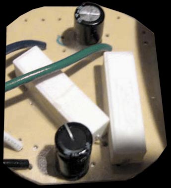
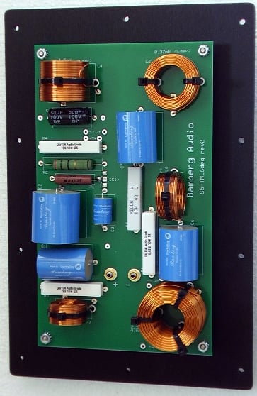
Poorly designed crossover (left pic); a high quality crossover (right pic)
The crossover (above left pic) is from a two-way bookshelf speaker system we have previously reviewed. The speaker system employs a stiff cone driver which has no crossover circuit (namely a LPF) to limit its bandwidth to reduce its audible break up modes at higher frequencies. The manufacturer chose to use an electrolytic capacitor as a measure of cost savings at the expense of performance as these parts have higher resistance and performance variances than quality and more costly poly designs. This is bottom of the barrel crossover design unbecoming of any serious loudspeaker design, despite the claims of “science and research” behind its products. At low power levels these speakers don't sound bad but once the volume is cranked up, audible driver break up was identified by our panel of listeners in blind comparisons.
The crossover image (right above pic) is of a much higher caliber design by an engineer making no outrageous claims. Instead, the engineer understands the importance of proper crossover design and execution to get the most out of the drivers. The designer invested an appropriate portion of the budget of his product to arguably one of the most important aspects of the speaker design – the crossover. Notice how air core inductors are used in critical circuit paths and they are properly oriented and spaced from adjacent magnetic inductors to avoid unwanted cross coupling.
The tweeter circuit runs vertically up the left side of the photo. The woofer circuit is on the right. You can see how the inductors are located in the corners, while the smallest inductor is in the middle of the board. Tweeter/woofer nearby inductors are oriented at dual-right-angles with each other. There literally is more woofer/tweeter crosstalk from single-wiring than there is through the inductor mutual coupling.
Interestingly the philosophy can be continued that it’s better to run a midrange driver full range in a 3-way system with no HPF element at all because it contributes to the overall bass output of the product. While there is some validity to this approach, care must be taken so that the actual driver can handle the stresses of being run full-range. It is noteworthy to mention a small midrange driver isolated in its own enclosure will limit its bass contribution to 80Hz or so. Any additional bass output the midrange may be providing is wasted below those frequencies where the small driver is inefficient at converting the power to sound. At the same time, not crossing over the midrange driver essentially keeps it in parallel with the rest of the system lowering the overall system impedance at low frequencies forcing the amplifier to supply more current to the loudspeaker that would ordinarily be needed if the crossover instead employed a HPF. It can be argued that this wastes amplifier power and increases the loudspeaker’s distortion and the chance of possibly shutting the amplifier down as a result of an unstable load impedance. A loudspeaker designed like this when turned up in volume has the potential to experience audible break-up from the midrange driver. This is especially true as it exceeds its excursion limits because of a lack of protection at high input levels at frequencies below the useful range of the driver. There are always exceptions to this, that hopefully a loudspeaker designer considers when choosing not to employ a HPF network on a dedicated midrange driver.
We rounded up several tower speakers a couple of years ago and found both trained and untrained listeners were able to identify a particular speaker running its midrange without a crossover in a blind listening test as subjectively having its vocals being slightly colored and tubby sounding, while also sounding strained at high output levels. In our option, a simple fix to their crossover by inserting a HPF would have greatly improved the sound quality of this speaker which in itself wasn’t a bad sounding speaker to begin with. It just needed a crossover fix that wasn’t too costly, but whose absence was easy to hear by even casual listeners in a controlled blind listening test. The speaker itself still scored very highly in our listening tests but we as Audioholics are always picking nits with all products we review to keep pushing manufacturers into making better next generation products that we can all salivate and eventually upgrade to.
Editorial Note about Running a Midrange Driver with No HPF by Paul Apollonio
By eliminating the series high-pass capacitor (at the VERY minimum) needed to protect the midrange driver from dangerous levels of peak low frequency content, this lowers the impedance of the system in a range where the output of the midrange driver adds NOTHING to the output of the Woofer(s); hence lowering system sensitivity. The low frequency content can cause increased voice coil movement and possibly cause it to go out of the gap if driven too hard, thereby allowing the low frequencies to modulate (read distort) the midrange the speaker produces. A sinewave sweep test to measure this problem will be unrevealing in this case. To see this problem, one must put in two frequencies simultaneously and view the output on a spectrum analyzer. (One can see distortion products as sum and difference frequencies) This is a simple process and one all audio engineers are familiar with.
Even if the Midrange driver is made INCREDIBLY stiff, and placed in a very very small sealed enclosure minimizing excursion and hence this distortion, subjecting the midrange voice coil to the heat caused by the low frequency content is generally not better than saving the price of the series capacitor.
There is such a thing as recommended practice and procedures, and the practice of eliminating the high pass filter, even if only a single series capacitor from the midrange driver is, in my opinion, NOT a good idea by any stretch of imagination. Allowing the large peak amplitudes of low frequency content to get to a midrange speakers voice coil is, in my opinion, not a very good idea.
Bottom Line: The KISS principle doesn't always work when it comes to building a crossover network for a loudspeaker. Take pause if you open the speaker box and see a 2 or 3 element crossover like the above left picture above, recognizing this was, in our opinion, done for cost reducing purposes and or design incompetence. While the speaker can still offer respectable performance nonetheless, it's likely not "state of the art" in performance like you would find in more robust and often more expensive alternatives.
Editorial Note by Phil Bamberg
Low-slope designs also allow higher tweeter excursion, leading to distortion or outright failure. For this reason (and those previously stated), most low-order designs sound strained when turned up loud. Designers that are not qualified to develop crossovers properly often tout the simple filter networks. They don’t have the knowledge and experience to handle more complicated circuits, or time delay, or phase, for example. For anything more complex than a second order crossover, the designer really needs a good modeling software program with a built-in optimizer. This is why I believe that some companies which are great at building quality cabinets still don’t have properly designed crossovers inside them. Things are improving in this regard, as more audiophiles are not accepting of poor sound from inferior crossovers installed inside beautiful cabinets.
Identifying Legitimately High Fidelity Loudspeakers: Crossover Coils & Capacitors
Myth # 2 – Magnetic core chokes are as good or better than air core chokes because they offer a lower resistance for a given inductance.
Audioholics has already published a series of articles on the ills and compromises associated with the use of magnetic cores in inductors. Inductors used in crossovers are usually by far the most expensive parts of the least visible and unfortunately most neglected parts of a speaker system, the crossover.
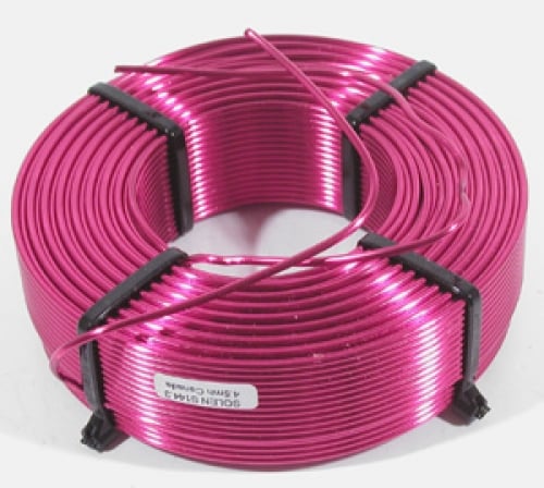
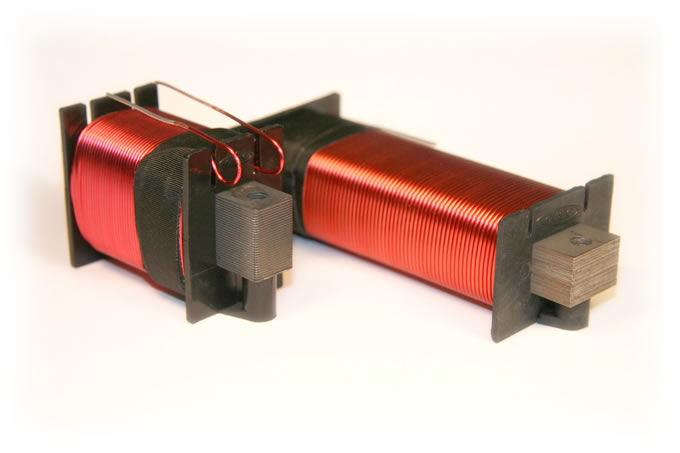
Air Core Inductor (left pic); Steel Laminate Core Inductor (right pic)
For more on this subject in detail, please see: The Crossover: the Brains of the Loudspeaker
If the listener does not push the system to a high output level, OR if the drivers used have considerably more distortion than is added by the use of magnetic core chokes, then it is a reasonable compromise to be made in a system with a tight budget. It does not follow because any set of listeners fail to detect a measurable difference due to cheap crossover parts that this is a difference which is “inaudible”. It simply means the rest of the system is distorting so badly that the distortion added by magnetic core chokes in the crossover is hidden by other distortions which mask it.
Given the high levels of measured distortion noted in our article: The Crossover: The Brains of the Loudspeaker Part II
The inability to hear this distortion would not constitute much of a recommendation for the speaker under test, or the listener doing the testing who swears he or she cannot hear the difference. “There has never been any shortage of people willing to claim a given level of distortion was inaudible” - Dave Hadaway, DB Systems
The argument is sometimes made that a lower impedance driver is more affected by changes in DCR of a coil than a higher impedance driver. This assumes the Re of the coil is constant, but it’s not which is paramount. Is it the ratio of Re in the crossover coil to Re in the voice coil that matters. Magnetic cores are chosen over air cores because of size and cost, not performance.
Editorial Note by Phil Bamberg
I use steel laminate coils for a woofer that crosses at 400Hz or lower but air cores for everything else. Transient speed is not the issue in this band, but a more constrained stray field from this large-value coil prevents mutual coupling to the other smaller air-core coils. Furthermore, the lower DCR from the laminate coil in a smaller package is desirable for the low-band woofer, because it effectively couples it more directly to the amplifier. This helps prevent signal compression.
What's often equally important to quality parts usage is taking the time to properly lay the parts out on the circuit board to ensure the inductors don't magnetically couple and create more distortion or crosstalk. Applying proper distance between coils and orienting them at 90 degrees (direction of turns) will minimize unwanted crosstalk and ensure the intended filter slopes are achieved.
For more information on this topic, see: Inductor Coil Crosstalk Basics
Bottom Line: Magnetic chokes are cheaper than air cores (with an equivalent DCR) so the loudspeaker engineer must weigh the tradeoff of the potentially increased distortion using magnetic chokes versus using larger more expensive air core counterparts when choosing which compromises are best for the system. If one does use magnetic core inductors, they must allow for sufficient core material in order to ensure their parts don't saturate before the loudspeakers blow up. They should also be using air cores chokes for small values (say below a few mH), and if they are not, they are simply saving costs or unable to recognize the distortion reducing benefits of using higher quality parts.
Editorial Note by Phil Bamberg
While this is true, I think location/orientation is very important, and the crosstalk is measurable. The overall physical size of the crossover impacts the level of crosstalk between the inductors. A physically larger crossover with higher-wattage components allows the designer more room to spread out the inductors. These crossovers are more expensive in several categories. As you say, the crossover is unseen, but its quality is surely on par with the visible drivers and cabinet.
Myth #3: There are no Advantages of using Polypropylene or Polyester (Mylar) capacitors over Non-Polar Electrolytic Capacitors in a crossover.
It may be that your box is so very small that trying to put a 25 uF Mylar capacitor in two places on your crossover along with those big heavy large diameter wire air core chokes makes the PCB (printed circuit board) SO big you can't fit it through any of the holes in your box. (I know because I have done it!) That said, an electrolytic capacitor will ALWAYS consume more power, run hotter, and have a shorter working life than a film (i.e., mylar, polypropylene, Teflon, etc.) capacitor of the same value and voltage rating as an electrolytic. That said, NO electrolytic made will work as well in a crossover as a film capacitor. However, their advantages over film are twofold:
1) Size (much smaller for a given value and voltage) and
2) Way less expensive than a film capacitor.
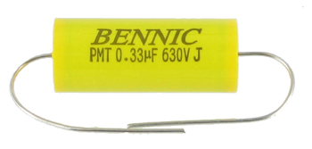
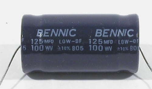
Metallized Polypropylene Capacitor (left pic); Electrolytic Capacitor (right pic)
This does not imply in any way that all electrolytics are created equal. They can be made with less packing density (capacitance per volume) and less loss (dissipation factor or DF for short.) While pretty much everyone uses electrolytics, it is always a decision based on size or budget or both, but many designers feel their use compromises performance.
Manufacturers that truly care about the sound quality of their products typically won’t use electrolytic capacitors in series with a tweeter. Unless the higher inherent DCR is desired in the circuit path of the crossover, they should typically be bypassed (connect in parallel) with smaller value film capacitors to greatly minimize the disadvantages of the electrolytic capacitors if used alone. If you ever get to take a peek inside of a loudspeaker you’re considering buying, looking closely at the quality of the parts and how they are implemented speaks volumes. We are not advocating the usage of uber expensive esoteric parts touting questionable performance characteristics. However, quality vs bad performing parts is easily quantifiable.
Editorial Note about Crossover Parts Quality by Steve Feinstein
In all fairness, the controversy over the audibility of different capacitor or coil types is one of the more heated topics in audio. While there may very well be theoretical reasons for preferring one type over another, many highly-regarded audio experts and designers don’t share the hysteria over capacitor or coil choice—at any price level— that others do assuming the parts selected aren’t operated beyond their limits adding their own measurable distortions. In the interest of ‘full disclosure,’ this should be pointed out.
Of far greater importance to my mind—and oft overlooked—is the subject of component tolerance and stacked variables. Regardless of type, if a manufacturer uses typical parts with a +/- 10% value variability, those tolerances can ‘stack’ (.9 x .9 x .9 x .9) in one direction or another, and your “oh-so-carefully-designed” crossover will not be at 2000 Hz. Instead it’ll be 1708 Hz or 2414 Hz, and it’ll vary from speaker to speaker. Good companies use 5% tolerance parts. Really good companies use 1% tolerance parts. This is as least as important as the arbitrary component type you choose. Of course, the consumer will pay more for close-tolerance parts, because more finished goods will fail QC.
Editorial Note by John L Murphy on Electrolytic Capacitors
If you elect to use electrolytic capacitors in a loudspeaker you take on a bit of an obligation to make sure that your loudspeaker does not become a fire hazard when operated at its rated power for long periods of time. Capacitors that operate safely at modest sound levels can rise in temperature quickly as the input power is increased to become actual fire hazards. Always check the temperature rise on ‘lytics. This is not a lesson you want to learn the hard way.
Editorial Note by Phil Bamberg
In some networks I use a single electrolytic cap in the RLC string placed across the tweeter terminals to flatten the resonant hump in the tweeter impedance curve. Typically this cap is around 50 microfarads – neither a small or large value. It is effective below around 500Hz, where the SPL is also far down in level. Placing a cap in series with the midrange driver may require a large value if the driver impedance is high, and/or the cross point is low. In such a case, a polypropylene cap is desired. But the large component value truly adds to its cost (tens of dollars).
Bottom Line: Electrolytic capacitors are cheaper than air poly or mylar parts so the loudspeaker engineer must pay extra care in design to ensure critical series circuits are bypassed with better parts in order to reduce deleterious effects caused by such parts if used within their crossovers. Using tight tolerance parts (5% or better) ensures consistent performance from speaker to speaker but many manufacturers skimp here solely for cost savings.
Myth #4: Loudspeaker Impedance Graphs Don’t Matter since we Don’t Listen to Them
While it’s true we don’t directly hear what an impedance graph shows us, it does tell us what kind of a load impedance it will present an amplifier. It also tells us how well the loudspeaker designer integrated the drivers and whether or not they properly chose the right crossover points and slopes for the system.
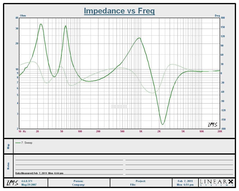
Impedance Graph of Poorly Designed Crossover Network of “High End” Bookshelf Loudspeaker
Here is an impedance graph of a pair of $2k/pair bookshelf speakers I was working on a review for. These speakers sounded pretty good but they kept shutting down our reference Marantz PM-11S2 200wpc Integrated Amplifier at high output levels during our listening tests. An impedance sweep of the speakers revealed a huge crossover design flaw as you can see by the 2 ohm dip at the systems 2kHz crossover frequency. This appears to be circuit resonance by incorrectly placing two components in parallel with each other. The speaker system was also tuned too low for a two-way bookshelf speaker using the driver they employed as you can see by the 40Hz saddle point in the impedance graph. Not only was the woofer bottoming out at around 75dB at the listening position, but even when we limited the bass output to the speaker, it was shutting down our amplifier because of the nasty 2kHz impedance dip. Sadly the manufacturer used all high quality parts and drivers and most notably beautiful cabinetry, but they didn’t properly execute the system design.
Editorial Note by Phil Bamberg
The dip seen at 2kHz is typical for a tweeter that needs some boost near the crossover frequency. In other words, there is essentially no resistance necessary in series with the first shunt coil in the tweeter network. If the tweeter needs to be padded down some, in order to better match the midrange efficiency, then there is an alternative method that both accomplishes the level matching and keeps the impedance high in this band. I believe that a good designer always “keeps one eye on the impedance” during crossover system design. While there may be an infinite number of circuit topologies that lead to virtually identical SPL responses, many are still not friendly from an impedance aspect. Below is the impedance curve with an easier impedance load. The 3kHz minimum impedance is still there for this different speaker, but it is now up at 5.5 ohms.
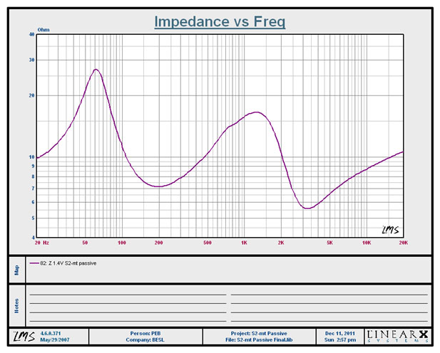
System impedance for properly designed 2-way bookshelf loudspeaker
The lesson here is that high quality parts and layouts are themselves no guarantee of success. An inept design will cancel out the advantage of superior components.
Bottom Line:
A trained observer can tell a great deal about a loudspeaker by just looking at the impedance and phase plots it produces. While we don’t hear what we measure from an impedance plot, it can predict how well a speaker will perform when being powered by a wide variety of amplifiers.
The next 3 pages of this article deal with:
- Baffle Step Compensation
- The Loudspeaker / Room Interface
- Power Response
Although these are not crossover related topics per se, the crossover design is ultimately a determining factor to how a loudspeaker will perform in these areas. You can simply jump to the Conclusion should you desire to read these topics in detail in the near future.
Identifying Legitimately High Fidelity Loudspeakers: Baffle Step Compensation
How a woofer propagates sound off the front baffle at different frequencies is an important consideration when designing a loudspeaker crossover that is often overlooked by many manufacturers. Philip Bamberg explains and graphically illustrates this concept below in the three LMS frequency response measurement of loudspeakers along with accompanying text as to what the measurements represent. His example focuses primarily on a two-way bookshelf speaker system. There are different approaches to accomplish the same task with multi driver speaker systems such as raising the crossover frequency on the HPF to the midrange but this goes beyond the scope of the article. This topic may be re-visited in greater detail in future articles.
For the typical 7” midwoofer speaker, it is important to assess the output level of the woofer without the crossover during the design process. Regardless of the response shape in the bass, the woofer’s output will be seen to rise with frequency. This is because the woofer experiences the transition of its acoustic environment from full space to half space, which is a 6dB step up in output. This phenomenon is commonly referred to as the Baffle Step. (Other commonly used phrases are diffraction loss or spreading loss.) In other words, at low frequency, the sound travels uniformly in all directions. But at high frequency, the sound becomes directional, and won’t expand behind the baffle. It’s as though the woofer is mounted in a very large panel, or half space. Since the output of the woofer cannot be artificially raised in the upper bass (160Hz), that point dictates the final speaker sensitivity, at least for a 2-way speaker. Therefore one primary job of the crossover is to tilt the rising response back to level, beginning at this frequency. The process is commonly called Baffle Step Compensation. Too often, speakers are designed to not fully compensate out this rise by beginning the compensation at a higher frequency, e.g. an octave higher at 400Hz, or even higher if at all. This inevitably makes the speaker more efficient in its upper range, but at the expense of sounding thin. It is possible that inexpensive speakers do this in order to gain apparent efficiency as well as save a little on the crossover cost.
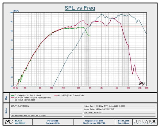
Raw driver response for 7” woofer / 1” dome tweeter 2-way bookshelf Loudspeaker
Here is the raw (no crossover) woofer (blue line) SPL graph for a 7” woofer and 1” dome tweeter (green line), mounted in a sealed 1/2cF cabinet. The thin red line was curve-fit to the woofer’s bass response, and level matched up to 200Hz. It also represents the predicted final speaker sensitivity of about 86dB. Venting the box at about 40Hz tune frequency could lift the middle bass by about 3dB, but there will be no lift at 200Hz. No matter how the 2kHz crossover is designed, it won’t impact the woofer’s output at 200Hz. Therefore it is important to “tilt” the rising woofer response back to level, starting at 200Hz. The thin brown line represents the woofer response with only a single 1.5mH coil in series with it. Notice how the woofer response is unchanged below 200Hz, but that it is also tilted down by up to 5dB at 1kHz. The tweeter is at least 6dB more sensitive than the woofer, and will have to be padded down.
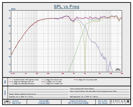
Final (with crossover) response for 7” woofer / 1” dome tweeter 2-way bookshelf Loudspeaker
Here is the same speaker, measured with the final 12-part crossover in place:
- Woofer/tweeter summed response is shown by the bold purple line. System sensitivity was reduced to 85dB to account for the losses from the two coils in series with the woofer. Cross point is exactly 2kHz. Phase coherency is proven by a flipped-polarity test measurement (shown by the thin gold curve). Final amplitude accuracy is +/-2dB.
- The bass response of the woofer is unchanged, but it is now level throughout the midrange. The woofer’s primary 4kHz peak is now 15dB below reference level.
- The tweeter output has been reduced to match the 86dB sensitivity. It is 25dB down from its raw output level at 1kHz, showing good tweeter protection during loud playback.
Identifying Legitimately High Fidelity Loudspeakers: Loudspeaker to Room Interface
Speaker designers today generally acknowledge the effect we call diffraction loss or “baffle step” by making adjustments in the loudspeaker crossover to reduce the treble by some amount approaching 6 dB. This issue arises because speaker designers usually design their systems based on the standard “half space” acoustic load…the equivalent of flush mounting the speaker system in an infinite wall with no other surfaces (walls) anywhere around. Why would we design for such a bizarre “room”? Well, our acoustics analysis is all based on that standard half-space load because that problem is solvable in a general mathematical way.
Loudspeaker simulations based on Thiele-Small analysis traditionally assume a half-space load. But speakers designed to deliver flat frequency response into a half-space load do not achieve that same result when placed in a real listening room. This is because in a real room the acoustic load is not constant but rather varies with frequency causing peaks at one frequency and dips at another. When designers address the diffraction loss issue they are beginning to step away from the assumption of the standard load and begin to broach the “final frontier” of loudspeaker design: the loudspeaker-room interface.
Consider that the frequency response of a loudspeaker is affected by its acoustic load in the same way that the power output from an amplifier depends on its electrical load. A power amp theoretically delivers twice as much power into 4 Ohms as it does into 8 Ohms. Analogously, a loudspeaker delivers twice as much power into quarter-space as it does into half-space. In the loudspeaker design process we can collect good half-space response data by testing the speaker using a so called “ground plane” measurement where the speaker is configured to be flush with the earth in a large open area that effectively achieves half-space loading over the audio frequency range. These measurements are generally in good agreement with our half-space simulations.
So as loudspeaker designers we do have good control over the frequency response of our systems up to the point of knowing the final acoustic load. This is the point where we have to leave the comfort of the standard acoustic load and move into the real world of an arbitrarily sized and shaped listening room with loudspeakers placed in some arbitrary location. Both the enclosure and the room introduce new variables into the analysis making the problem much more difficult. In moving out of the laboratory and into the listening room we first address the finite sized baffle. Recognizing the finite baffle of a real loudspeaker is the first step away from the standard half-space load. This analysis leads to the prediction of a 6 dB drop in lows compared to the standard load. So we compensate by reducing the highs about 6 dB at a frequency that depends on the baffle size. This allows us to get a predictable response for the loudspeaker system when placed not on an infinite plane but rather in an enclosure (located in free space) with a known baffle size. So now we have a speaker that can deliver a flat frequency response when placed in a finite enclosure located in free space. It’s a step (pun intended) in the right direction.
The difference between a half-space load and the load the speaker “sees” when placed in your listening room is substantial and accounts for the vast majority of frequency response “error” in any audio playback system. For the standard half-space load every frequency in the audio spectrum sees a constant load much like a power amplifier driving an 8 Ohm test resistor. In your listening room only the highest frequencies have the benefit of the standard acoustic load. This is because the wavelengths of the high frequencies are shorter than the dimensions of the front surface of the speaker (the baffle). At lower frequencies starting at the frequency where the wavelength is similar to the dimensions of the baffle the acoustic load is reduced to full space with a 6 dB reduction in output.
At frequencies below the baffle step region the load stiffens again as the wavelength approaches the size of the room dimensions. Not only is the acoustic load stiffened back to the equivalent of half-space (0 dB) but perhaps to the even more stiff load of quarter-space (+6 dB, two wall corner) or eighth-space (+12 dB, three wall corner) loading. Except for leaks in the room the frequency response would increase at 12 dB per octave at falling frequencies due to the stiffness of the air in the enclosed room. So the room can easily introduce variations ranging from –6 dB to +12 dB and beyond compared to the standard half-space acoustic load. But analyzing these broad changes in the acoustic load only takes us so far.
Commonly Specified Acoustical Loads & Associated Output Differences:
|
|
Full Space = 4 pi steradians This represents radiation into free space, that is in the open with no walls, floor or surfaces nearby. 0 dB reference |
 |
Half Space = 2 pi steradians (commonly specified
speaker load) If you imagine putting a speaker on an infinitely large baffle then the front of the speaker would be radiating into half space. The plane divides all of space into two halves. +6dB SPL increase compared to full space |
 |
Quarter Space = pi steradians Imagine the speaker placed at the intersection of two infinitely large perpendicular planes. Approximated by the intersection of two walls. The two planes divide all of space into four quarters. +12dB SPL increase compared to full space |
 |
Eighth Space = pi/2 steradians (1/8th freespace) Now, imagine the speaker placed at the intersection of three walls, such as in the corner of a room The three planes divide all of space into eight parts. +18dB SPL increase compared to fullspace (not factoring in ceiling contribution of the room) |

Images and definitions courtesy of True Audio
Superimposed on the broad variations described above are numerous smaller peaks and valleys which are best understood when we consider the reflected images added by the room. Unless you listen to music in an anechoic chamber then each of the six surfaces of your listening room provides a reflection of the loudspeaker which is then reflected repeatedly by the other room surfaces to create a very complex sound field. It is precisely these reflected images of the speaker system that combine to give the overall frequency response perceived at the listening position. You can think of the half-space load as exactly equivalent a single reflection (adding 6 dB) compared to free space. Analysis of the effect of the room reflections by way of the “image method” leads us to the same overall results as more crudely analyzing the “load” seen by the system as described above. These two different views on the same problem give a designer a broader perspective on the overall problem of delivering a controlled frequency response to a listener in an arbitrary room. At this point the designer can only target some representative room and optimize the response for that room.
A well designed, off-the-shelf, high performance loudspeaker system in 2011 is likely to address the baffle step so that the bass is balanced. But even the best loudspeakers cannot address the frequency response aberrations unique to your room, speaker placement and seating geometry without first measuring the in-room response and then applying corrective equalization. For the highest frequency response accuracy custom voicing will almost always be necessary. This involves the measurement of a spatially averaged frequency response at the listening position followed by custom equalization to achieve some targeted frequency response. The desired response for a playback system is nominally considered to be “flat” but in reality “house curves” are almost always employed to accommodate the broad variations in our libraries of music and cinema. For example, the standard voicing for cinema theaters is the “X-Curve”. While the consumer audio industry pays lip service to “flat response” there is no official “standard” and very few commercial loudspeakers actually deliver anything close to a flat (spatially averaged, in-room) frequency response. That’s a good thing, because with most program material from the past 50 years listening to such a loudspeaker is not an enjoyable experience but rather an exercise in tolerance and endurance. As with many things in life, finding the optimum frequency response is a question of balance.
When using a digital equalizer as part of an overall loudspeaker system design it becomes possible to have not just one frequency response but a wide array of various “voicings” just a click away. Traditional passive loudspeakers may have a “tweeter switch” to provide two or three tweeter level settings but modern digital equalizers allow you to keep settings such as:
a. In-Room Flat
b. X-Curve (the cinema standard voicing)
c. Small Room X-Curve
d. 7.5 dB Tilt (20 to 20k Hz, decreasing treble)
e. 5 dB Tilt
f. 4 dB Tilt
e. Dance Party EQ
f. Concert EQ
g. Live Performance EQ
h. Juke Box/Dance Party
 Here
the addition of the digital EQ has also introduced the possibility of “flexible
voicing” to help offset the considerable variation found in our music
libraries. In-room flat response makes for a nice laboratory standard for the
calibrated playback of specially prepared source material but it is not the
appropriate playback voicing for a music library consisting of music recordings
spanning the last half century. A little voicing flexibility can facilitate the
enjoyable playback of a much wider range of recordings than any loudspeaker
system with a single fixed voicing. How many times have you heard something
like this: “these speakers are so accurate they make older recordings sound
really bad”? The recording was (is) actually just fine; it was simply being
played back with the wrong “decoding” equalization. After all, each recording
in our library is effectively “encoded” with the voicing (frequency response)
of the monitor loudspeakers on which it was originally mixed and/or mastered.
If a record was mixed on a monitor which had the treble reduced then playing it
on a monitor voiced flat will be an unpleasant, un-musical experience. Playing
that recording on a monitor with the “correct” (for that recording) tilted
response will reveal the musical performance as it was intended to be heard.
Here
the addition of the digital EQ has also introduced the possibility of “flexible
voicing” to help offset the considerable variation found in our music
libraries. In-room flat response makes for a nice laboratory standard for the
calibrated playback of specially prepared source material but it is not the
appropriate playback voicing for a music library consisting of music recordings
spanning the last half century. A little voicing flexibility can facilitate the
enjoyable playback of a much wider range of recordings than any loudspeaker
system with a single fixed voicing. How many times have you heard something
like this: “these speakers are so accurate they make older recordings sound
really bad”? The recording was (is) actually just fine; it was simply being
played back with the wrong “decoding” equalization. After all, each recording
in our library is effectively “encoded” with the voicing (frequency response)
of the monitor loudspeakers on which it was originally mixed and/or mastered.
If a record was mixed on a monitor which had the treble reduced then playing it
on a monitor voiced flat will be an unpleasant, un-musical experience. Playing
that recording on a monitor with the “correct” (for that recording) tilted
response will reveal the musical performance as it was intended to be heard.
As designers move more toward integrating power amplifiers and line level signal processing into their loudspeakers we open up new possibilities with active crossovers, fine frequency response correction and flexible overall voicing.
For more reading on this topic check out: Loudspeaker Diffraction Loss & Compensation by John L. Murphy
Identifying Legitimately High Fidelity Loudspeakers: Power Response & Baffle Step
Regarding half-space measurements, they originally were the result of Acoustic Research’s (AR’s) exhaustive measurements back in the 1960’s. AR was one of the first speaker companies to do detailed, repeatable scientific speaker measurements and publish them with accurate explanations that the average consumer could understand. Back then, many speakers were in fact mounted on “bookshelves,” with books all around the speaker, constituting a measurement environment that did, indeed, approximate a true 2 Pi (half-space) environment.
When that same speaker was mounted on a stand somewhat away from the major room surfaces (the side wall, the wall behind it, and up from the floor below it), the speaker would exhibit what today we call the “baffle step” phenomenon.
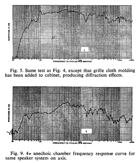
The above curves of the famous AR-3a from 1968 clearly show that. In the top figure, the 3a is in a pure 2 Pi environment (“bookshelf,” surrounded by books), and its LF-to-midrange response is smooth and predictable.
In the lower curve, the 3a is stand-mounted away from the walls. You can clearly see the lowering of the woofer’s response level as the frequency transitions from a 2 Pi environment (in the midrange, where the speaker’s baffle is large enough to provide that environment) to a 4 Pi environment in the lower bass. Interesting that AR recognized this and identified it in 1968. They were ahead of their time. But not until Roy Allison’s Allison speakers of 1974 were there speakers that took this into specific account. Allison’s 1973 AES article The Effect of Room Boundaries on Low Frequency Power Radiation is particularly illuminating.
The concept of Power Response vs. On-axis first arrival frequency response is regarded by many as way to take this entire matter into consideration with measurements. By measuring the speaker’s total radiated output in all directions at all frequencies in the reverberant field (not just in the near field, 1M on axis), proponents of the Power Response approach feel that that is a more relevant, realistic way to characterize and predict how a speaker will sound to a listener in a real room, under real-world conditions.
Boiled down into simple terms, the first-arrival crowd feels that the on-axis, first-arrival “anechoic” frequency response is what the ear grabs onto first and that sound is the primary determinant of a speaker’s essential sound/tonal quality. They feel that the room reflections, driver interaction, phase considerations, etc—however closely in milliseconds those reflections and artifacts may follow the ‘first arrival’—are separated out by the brain/ear system and what you fixate on is that first arrival.
Balderdash, says the far-field power response crowd. The room reflections etc. are so close in time to the first arrival that they swamp the first arrival completely, leaving the overall far-field energy output of the speaker—the so-called “power response”—as what you hear to determine the tonal quality of that speaker. Only if you sit very close to the speaker—say, within 2 or 3 feet, on axis—does the first arrival response really count. Once you’re back about 6-8 feet (ie. farfield of the speaker), most of the first arrival sound is simply folded into the far-field power response. It is the far-field response and more specifically the early reflections from the sidewalls that dominate what we hear in small room acoustics.
Of course, the two are not mutually-exclusive. As a speaker designer, you can reduce near-field diffraction, correctly align your drivers, etc, do all kinds of things to optimize the near-field first-arrival sound without hurting or negatively affecting the far-field power output. That is what most good speaker designers do—they optimize the near-field response “just in case” it makes a difference.
Test it Yourself
There’s a great test you can perform yourself at home that perfectly demonstrates the difference between near-field and far-field response. You don’t need any expensive test equipment. As a matter of fact, you don’t even need a Radio Shack SPL meter.
You need a pillow. Preferably, a sofa pillow, maybe 12” x 12” or so. That’s it.
Here’s what you do: sit close to the speaker, about 2 feet away. Play only one speaker. Use some full-range music that is rich in upper-midrange and treble content. (Jazz is good for this, because it has lots of cymbals, “reedy”-sounding saxophones, and piano upper harmonics.)
Listen to the music. Now hold the pillow up in front of your face so that your line of sight to the speaker is blocked.
Lower the pillow away from your face. Note the difference in the sound depending on whether the pillow is raised or lowered. When the pillow is raised in front of your face, the speaker’s sound becomes noticeably duller and muffled. This is because the majority of the high frequencies reaching your ear are the result of the speaker’s direct radiation, right from the tweeter to your ear, on a straight line. So when the pillow is raised, it blocks and absorbs those highs, and you can’t hear them. This is the “near field,” and what the pillow is interfering with is the so-called “first-arrival” sound.
Now move back to your normal listening position, about 8-10 feet away from the speakers. Repeat the test: Play the music and listen with the pillow sitting on your lap. Now play the same music and raise the pillow in front of your face. You’ll notice something pretty surprising: the sound is almost (note: not absolutely) identical whether the pillow is raised or lowered. This is because you’re now sitting in the far field, and almost all the high frequencies are reaching your ears by way of room reflections and indirect sound—not on a straight line like in the near-field example.
The wider a speaker’s high-frequency dispersion, the more this will be true, because a wide-dispersion speaker generates more room reflections than a narrow-dispersion speaker. As a generalization, one could say that a speaker with a 1” dome tweeter will generate more room reflections than a horn speaker with an intentionally limited radiation pattern.
So all those near-field considerations like driver alignment, cabinet diffraction, phase relationships, etc. are far less important in real world listening conditions than their theoretical importance might suggest.
Identifying Legitimately High Fidelity Loudspeakers: Crossovers Conclusion
 Take
your time when shopping speakers and make sure you ask the right
questions. First, it’s important to
understand the design goals of the loudspeaker engineer who designed the
speakers you are considering to purchase.
A company that downplays the importance on using high quality (not
necessarily expensive) parts as being inaudible in a blind test, while at the
same time making sophomoric mistakes in their product designs like running a
small midrange driver full range in a 3-way loudspeaker system, may not realize
the masking effects leading them to false conclusions in the first place. A lot can be told about the crossover design
of a loudspeaker system by carefully observing its impedance profile. No matter how much science a loudspeaker company may tout leading them to certain design choices, without careful observation of their "science" one cannot be sure of its accuracy. It's easier and often more profitable to justify using cheaper parts or less elaborate design practices than to take the time and do it right.
Take
your time when shopping speakers and make sure you ask the right
questions. First, it’s important to
understand the design goals of the loudspeaker engineer who designed the
speakers you are considering to purchase.
A company that downplays the importance on using high quality (not
necessarily expensive) parts as being inaudible in a blind test, while at the
same time making sophomoric mistakes in their product designs like running a
small midrange driver full range in a 3-way loudspeaker system, may not realize
the masking effects leading them to false conclusions in the first place. A lot can be told about the crossover design
of a loudspeaker system by carefully observing its impedance profile. No matter how much science a loudspeaker company may tout leading them to certain design choices, without careful observation of their "science" one cannot be sure of its accuracy. It's easier and often more profitable to justify using cheaper parts or less elaborate design practices than to take the time and do it right.
On the flip side, just because a designer does in fact use high quality parts, doesn’t mean they properly executed the design. Proper design execution is equally important to utilizing quality parts. Pay close attention to our loudspeaker reviews and how we discuss frequency response performance as well as the impedance and phase profile of the product. The impedance curves may seem strange at first, but they reveal a lot about the system and its flaws to a trained eye.
Recognize that no matter how well a speaker may apparently measure in an anechoic chamber based on some smoothed or low resolution captured curves generated by the marketing department of the company in question, one must take a closer examination of the loudspeakers overall on/off axis and power response at meaningful output levels. Most companies will NOT furnish this data. We attempt to always test speakers to their limits and comment on how they “misbehave” under such loading conditions. How a speaker performs in a real room speaks volumes for how the designer paid attention to detail in the final design and voicing of the product. This is a step often overlooked by loudspeaker designers whose primary aim is for a flat on axis anechoic response curve.
Acknowledgements
I would like to personally thank the following people for their contributions and/or peer review of this article, all of whom are true experts in their respective fields. Their contributions enabled us to make the most comprehensive and accurate article possible on the very complex topic of loudspeakers cabinets dealt with herein.
- Paul Apollonio, CEO of Procondev, Inc
- Philip Bamberg of Bamberg Audio
- John L. Murphy of True Audio
- Steve Feinstein, Director of Marketing & Product Development for Atlantic Technolgy
- Shane Rich, Technical Director of RBH Sound
- Dr. Floyd Toole, PHD & Chief Science Officer of Harman
- Ed Mullen, Directory of Technology & Customer Relations of SV Sound
- Identifying Legitimately High Fidelity Loudspeakers: The Economics of Cost Cutting
- Myths & Facts about Loudspeaker Cabinets: Identifying Legitimately High Fidelity Designs
- Loudspeaker Drivers: Identifying Legitimately High Fidelity Parts
- Comb Filtering, Acoustical Interference, & Power Response in Loudspeakers
Gene manages this organization, establishes relations with manufacturers and keeps Audioholics a well oiled machine. His goal is to educate about home theater and develop more standards in the industry to eliminate consumer confusion clouded by industry snake oil.
View full profile