
Myth vs Reality – Putting Cat5E-Based A/V Structured Wiring In Its Place
Sending audio, video and control signals over twisted pair cables have become common practice in the contemporary marketplace. There is a good reason for this. Twisted pair cables are cheap, ubiquitous and comfortably familiar to anyone with any level of installation exposure to data networking and telephony. UTP-based A/V installations are appealing for their perceived low cost and performance advantages. Widely accepted as a panacea that banished the need for task-specific cables to the equipment closet of history, those who universally advocate the use of balun-based infrastructure would do well to remember the words of Plutarch; “To find a fault is easy; to do better may be difficult.” This document will examine the advantages and disadvantages of Cat5E-based structured wiring installations as contrasted with direct connection using conventional point-to-point coaxial solutions.
What is a Balun?
Most audio and video connections natively operate in a single-ended environment. Single-ended, in this context, means an unbalanced line. This is usually coaxial cable whose conductors have unequal impedances with respect to ground; the opposite of a balanced line. Since all video signals, and most audio signals, are single-ended by nature they must be converted to the balanced environment through some type of manipulation. This conversion can be either active (requiring a powered device that fundamentally changes the nature of the signal) or passive (requiring a transformer or other device that is energized by the signal itself). Active conversion, as you might expect, can be expensive because, at its core, it implies the need for a complex component or device complete with a power supply and interface.
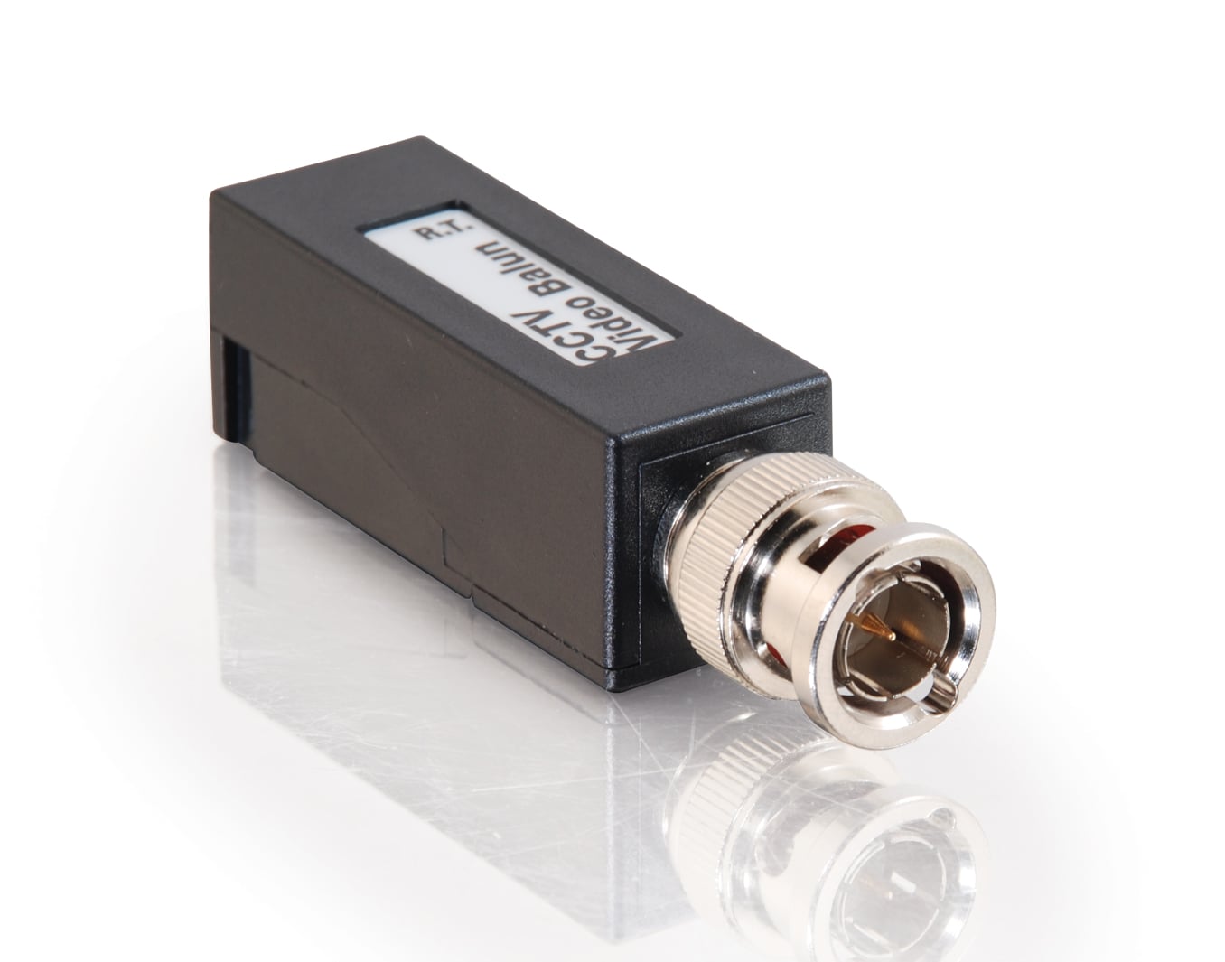 Passive conversions are traditionally accomplished via a
device called a balun (Balanced-to-Unbalanced), a type of transformer. Baluns always involve some form of electromagnetic
coupling and have long been used for radio and television broadcasts. In fact, one can be found on just about every
off-air television “rabbit ears” antenna.
It is the small, inexpensive part that converts the two wires of the
antenna lead (300-ohm) to the single round coaxial cable input (75-ohm) on the
television. A passive balun is built like most transformers are built; by
wrapping a certain amount of wire in a specified pattern around a ferrite
core. There is no need for integrated circuits
nor on-board power supplies and voltage regulation. There are no sophisticated manufacturing
processes involved.
Passive conversions are traditionally accomplished via a
device called a balun (Balanced-to-Unbalanced), a type of transformer. Baluns always involve some form of electromagnetic
coupling and have long been used for radio and television broadcasts. In fact, one can be found on just about every
off-air television “rabbit ears” antenna.
It is the small, inexpensive part that converts the two wires of the
antenna lead (300-ohm) to the single round coaxial cable input (75-ohm) on the
television. A passive balun is built like most transformers are built; by
wrapping a certain amount of wire in a specified pattern around a ferrite
core. There is no need for integrated circuits
nor on-board power supplies and voltage regulation. There are no sophisticated manufacturing
processes involved.
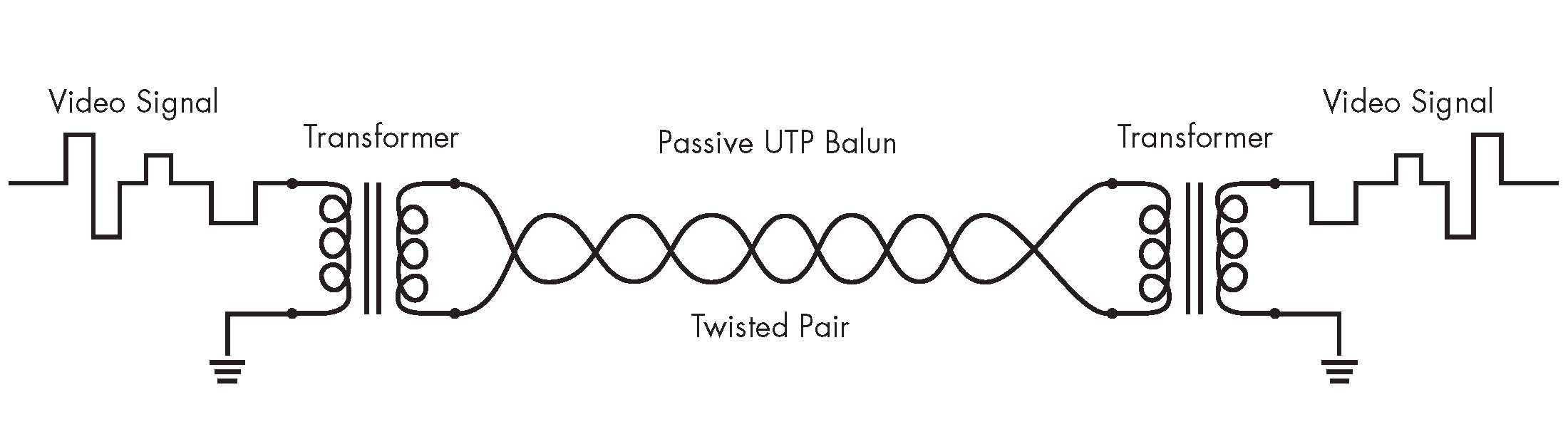
Audio, video and presentation balun-based infrastructure is most often installed on a Cat5E backbone. Category 5 cable includes four twisted pairs in a single cable jacket and typically features three twists-per-inch of 24-gauge copper wire. The wires are twisted to decrease interference and noise during balanced operation, where-in the wires carry equal-but-opposite signals (differential mode). In an A/V installation, a balanced line is a transmission line consisting of two conductors (wires) of the same type with equal impedance to ground and other circuits. In theory the common-mode noise from the two wires cancels each other when the two signals are added together at the destination because they both carry similar amounts of electro-magnetic interference (EMI) that are 180-degrees out of phase. Differential mode also reduces electromagnetic radiation from the cable, minimizing interference to adjacent wiring and circuitry. It is this ability to operate in a fully differential mode that makes balanced transmission desirable.
What does the Balun do to the signal?
 To understand the answer to this question we must first
understand the meaning of impedance.
Impedance is the total resistance to the flow of electrical current
presented by the combined elements of simple resistance, capacitance and
inductance in a conductor as seen by an AC source. The unit of measure is ohms. Impedance matching, including impedance
bridging, is the practice of setting the output impedance of a signal source
equal to (or less than, depending on design requirements) the input impedance
of the load to which it is connected.
This is done to maximize the power (or voltage) transfer and minimize destructive
signal reflections from the load.
To understand the answer to this question we must first
understand the meaning of impedance.
Impedance is the total resistance to the flow of electrical current
presented by the combined elements of simple resistance, capacitance and
inductance in a conductor as seen by an AC source. The unit of measure is ohms. Impedance matching, including impedance
bridging, is the practice of setting the output impedance of a signal source
equal to (or less than, depending on design requirements) the input impedance
of the load to which it is connected.
This is done to maximize the power (or voltage) transfer and minimize destructive
signal reflections from the load.
In addition to conversion between balanced and unbalanced signal modes; baluns of the type discussed here provide impedance transformation. The balun used in the example above, between “rabbit ears” and the television’s antenna input, uses an impedance-transformation ratio of 1:4 (alternatively 4:1) to match the 300-ohm twin-lead antenna feed to the 75-ohm coaxial port. Baluns used in converting audio and video signals for transmission via Cat5E typically have a transformation ratio of 1:1.3 (4:3) to match the nominal 75-ohm source impedance with the characteristic 100-ohm impedance of the UTP transmission line.
Because a balun is a simple device that is easy to build it is often also the target of commodity pricing. Just because a device is simple doesn’t mean it isn’t important! We know now that a baluns job is to balance the signal and to match the impedance of the source to the transmission line. To the extent that a balun is poorly constructed it can have adverse and unpredictable effects on the signal. Just as every chain is limited by the strength of its weakest link, so the performance of a balun-based transmission system is limited by the quality of the balanced-to-unbalanced conversion. Here are some considerations to be factored into the selection of a balun:
- If the turns ratio and geometry of the autoformer (balun transformer) are flawed then the impedance will not meet stated values and it may change dramatically as the frequency of the signal changes.
- Both the geometry and the material content of the autoformer affect the linearity of the transfer function. Impurities in the ferrite core and/or the precision of the wire wraps within the assembly can change the expected impedance and transformation ratio.
- As with all passive devices there is some insertion loss. The nature of a transformer is such that the insertion loss will always be greater, in terms of the absolute signal strength, than comparable losses attributable to a straight connection. Insertion loss of a balun is typically in the range of 1 to 1.5 decibels.
Balanced Operation and the Installation Environment
![]() Using twisted pair transmission technology, audio and video
signals can be transmitted 500 feet or more.
The nature of the differential (balanced) signal is such that noise,
both EMI (electro-magnetic interference) and RFI (radio frequency
interference), introduced along the length of the cable is cancelled. The noise is introduced into both
differential signals equally and of the same polarity. This is called common mode noise. When the two signals are combined at the
receiver the noise is subtracted, resulting in a clean signal transmission.
Using twisted pair transmission technology, audio and video
signals can be transmitted 500 feet or more.
The nature of the differential (balanced) signal is such that noise,
both EMI (electro-magnetic interference) and RFI (radio frequency
interference), introduced along the length of the cable is cancelled. The noise is introduced into both
differential signals equally and of the same polarity. This is called common mode noise. When the two signals are combined at the
receiver the noise is subtracted, resulting in a clean signal transmission.
Most implementations of balanced connectivity also protect against ground loops. Because the balanced signals are isolated from their single-ended inputs and outputs, the ground plane is interrupted. This is one of the strongest arguments for a Cat5E-based installation as, in the context of the typically longer distances involved in the system, the likelihood is high that the AC power system will exhibit differing ground potentials.
Finally, no analysis of balanced connectivity would be thorough without examining the potential cost savings of twisted pair cabling. Cat5E in bulk is smaller, cheaper and lighter than any equivalent length of coaxial cable. As connection lengths grow to the point where peaking amplifiers become necessary, the cost advantage of a twisted pair installation becomes even more evident. Small physical size also allows for easy installation within conduit and in tight quarters.
These strengths must be weighed against the schema’s weaknesses. A twisted pair’s susceptibility to electromagnetic interference depends on the twisting schemes staying intact during the installation. As a result, twisted pair cables have stringent requirements for maximum pulling tension as well as minimum bend radius. The fragility of twisted pair cables makes the installation practices an important part of ensuring the cable’s performance.
Signal skew, due to differing lengths of the twisted pairs within the Cat5E assembly, can cause color degradation at the display. Because the RGB components of the signal are sent separately through matched pairs of conductors, any skew affecting signal propagation can manifest as improper color convergence, decreasing both the resolution and the color accuracy of the final image. This deleterious effect may be exacerbated by larger display screens.
Total bandwidth, too, can be an issue. An autoformer is designed for a specific bandwidth and, as the signal deviates from the specified target frequency, the insertion loss raises, truncating bandwidth. Truncated bandwidth equates to compromised resolution. In its on-line marketing material covering balun-based connectivity solutions Extron® states; “While such devices are suitable for composite video and S-video signal transmission at short distances — less than 100 feet (30 meters), Extron does not recommend them for computer-video signals or HDTV, since their performance is compromised at frequencies relevant to high resolution video.”
Finally, UTP connections may actually suffer at distances that are too short. Many Cat5E baluns and active devices are designed to provide signal shaping or pre-peaking in anticipation of capacitive and resistive signal losses over long distances. Using a Cat5E based installation design for runs shorter than 50-feet increases the risks of signal degradation due to possible signal overload at the receiver.
Conclusion
A/V distribution over twisted pair cabling such as Cat5E has had a profound effect on system design and installation. Using active devices or transformers to balance an A/V signal and change its characteristic impedance, thereby allowing for the use of less expensive cable, has precipitated an explosive growth in remote display applications. From multiple viewing locations in a residential installation where all locations share common source components to sophisticated digital signage systems that combine text, image and live video elements, the ability to distribute control, sound and video signals efficiently and inexpensively has positively impacted our expectations of A/V technology.
Pros
- The use of a Cat5E-based A/V distribution system is one of the most efficient ways to distribute video, text and still image content to displays at distances from 75-feet to more than 500-feet.
- The performance of a Cat5E-based system can be easily tailored to specific needs through careful implementation of passive or active transmission. The greater the importance of absolute performance, the greater the need for an active solution.
- Cat5E is an inexpensive and readily available cable. When considering the needs of an A/V distribution infrastructure, a Cat5E cable is preferable to a Cat6 because of lower skew. This further helps to control costs.
- Cat5E-based systems provide common-ground isolation preventing ground-loop interference as an inherent benefit of their design.
Cons
- Baluns are not the ideal solution for every application; environments with excessive RF interference, such as factories with large AC motors or facilities with large numbers of fluorescent lights are particularly challenging.
- Baluns are not the best solution for runs under 50-feet where signal overload or frequency anomalies may degrade the image. At such short runs the cost-benefit ratio of Cat5E A/V distribution breaks down also, making high-bandwidth native connection a better choice.
- Baluns are not the best solution for very large screen displays using wide-bandwidth signals such at HDTV due to possible truncation of bandwidth and attendant loss of resolution or color quality.
- Balun-based installations, in high performance
situations, may exhibit skew-induced color distortions demanding expensive
active devices and negating any cost benefits.
A sales and marketing professional, Joe holds degrees in Electrical Engineering and in Applied Business. He has been honored several times within the consumer electronics industry, being selected to serve as a judge for the prestigious Consumer Electronics Association "Mark of Excellence Awards" and having served on the Board of Directors of the Satellite Broadcasting and Communications Association.
View full profile