
Whole House Wiring Basics Part 4
Whole House Wiring Part 4
Special thanks to Impact Acoustics
Television is the first truly democratic culture - the first culture available to everybody and entirely governed by what the people want. - Clive Barnes
CATV, MATV and other RF Tricks
Welcome to the fourth installment of our continuing exploration of signal distribution for the residential installation. In part one of Whole House Wiring Basics we explored various aspects of multi-room and/or multi-zone media design and implementation. Part two expanded our examination to include quality transport of analog video signals such as component, s-video and composite from point-to-point. Part three explored the distribution of digital video signals; HDMI and DVI-D for those just entering this hobby. There is a lot more to cover and today we’ll examine one of the oldest of the distribution disciplines – and one that can give you the most trouble. Even though antenna distribution (aka RF, MATV or CATV distribution) has a long and well-documented history, there are aspects of good RF system implementation that border on a dark art. Many are the antenna systems that look good in principle but end up delivering snowy, compromised performance on all – or just one or two – of the ports on the network.
RF stands for “radio frequency” and describes the signals we’ll try to shuttle from one room to another without compromise. The moniker MATV is an acronym for Master Antenna Television and is used to describe an RF distribution scheme that sends signals from a single antenna to multiple locations, usually within the same edifice. CATV, as may now be guessed, is Community Antenna Television (sometimes erroneously called “cable antenna television”) and dispenses with the large Yagi multi-element antenna on the roof in favor of a single coax pre-loaded with all your favorite channels by the friendly local cable service provider.
The contemporary RF system is far more complex than anything that was needed years ago. Once upon a time we needed to concern ourselves with notch filtering adjacent channels at the head-end, balancing signal strength, and delivering a spectrum that ranged from 55MHz to 800MHz without undue roll-off or, especially, RFI or EMI. This, by itself, is not without challenges. But today we have a more robust puzzle. A contemporary RF distribution schema must provide all that bandwidth and more. It must include provisions for bi-directional communication to accommodate Internet connectivity. It has to be amenable to both linearly polarized signals (standard RF broadcast) and circular polarization (satellite broadcast and new digital OTA signals). Finally the fully functional MATV installation needs to be able to handle satellite RF frequencies (950 to 2050MHz), low frequency control signals, and even DC power! Sometimes its hard to believe that one run of coaxial cable can do all of that, but indeed it can. To have a complete home media system your plans must include a proper RF distribution set-up.
This article won’t discuss antenna design. That is a topic best covered on its own. For those who want to know which antenna will best serve their particular circumstances, I refer you to the AARL Antenna Handbook – one of the best resources for the do-it-yourself enthusiast. This paper will assume that you have a quality RF source at your doorstep (a large assumption in the face of typical cable installation practices) and will examine the steps, considerations and pitfalls of distributing it to various rooms without signal loss. This paper will touch only lightly on local modulation; once again that is a topic worthy of its own dissertation. Finally this paper will not consider AM radio reception, which is a discipline in itself. An FM/TV antenna is as different from an AM radio antenna as a satellite dish is from a DVD player!
When creating an MATV system, and before getting into the specifics of the installation, you must decide on the type of distribution you want. There are two possible lay-outs. To add spice to the RF stew, it’s also possible to combine the two to make a hybridized distribution system. You must choose between a “home run” layout where the coaxial cable from each antenna locations runs directly to a single distribution point in the equipment closet, or a “trunk” layout where each antenna drop is tapped into a master trunk. Each system has its own merits and deficiencies.
A home-run system is exactly what it sounds like. Each coaxial cable runs directly from the antenna port in the remote location home to the master distribution location where it is connected to a multi-port distribution block. This configuration is sometimes known as a “star topology.” The advantage of this layout is an easy opportunity to control interference from port-to-port, easy solutions for ground-loop interference, and ease of balancing delivered signal power. Additionally a home-run system simplifies equipment selection as field measurements are predictable and system performance often mimics theoretical expectations to a great degree. The disadvantage is that you’ll end up running a lot of coaxial cable and you’ll have to deal with a large bundle of cables at the demarcation location.
A trunk-based system uses a single master “trunk” line to distribute the signal. Each drop is then set off a tap. The number of taps must be carefully analyzed to provide balanced signal levels at each drop location and the entire system must be properly terminated to maintain 75-ohm characteristic impedance. A trunk system’s greatest advantage is the ability to cover lots of space with a minimal amount of wire. A single line can be run several hundred feet and feed dozens of drops. The disadvantage is that every device connected to the trunk can affect every other device, so careful planning and equipment choice is critical.
Whole House Wiring - Understanding Coaxial cable
Coaxial cable might appear to be a simple wire with a solid center conductor, a circumferential outer conductor, and an insulator separating these two conductors. All coax is not created equally and you must know what to use to maximize performance and dependability. Television antenna systems require a 75-ohm cable. The significance of the characteristic impedance comes from concepts involving power transfer in electrical circuits. Specifically, 75 Ω is a good match for a center fed dipole antenna, the type of antenna almost always used for OTA television and radio reception. The characteristic impedance of the cable is determined by the ratio of the size of the center conductor as it relates to the size of the dielectric.
Why coaxial configuration? Coaxial lines confine the electromagnetic wave of the signal to the area inside the cable, between the center conductor and the shield. Because of this, coaxial lines can be bent and moderately twisted without negative effects, and they can be strapped to conductive supports without inducing unwanted currents in them. In short, coaxial cables allow efficient installation practices. In radio-frequency applications up to a few gigahertz, such as in the antenna distribution discussed here, the wave propagates only in the transverse electric magnetic (TEM) mode, which means that the electric and magnetic fields are both perpendicular to the direction of propagation. Above a certain cutoff frequency, transverse electric (TE) and/or transverse magnetic (TM) modes can also propagate, as they do in a waveguide. This means that coaxial cables are designed with an anticipated cutoff frequency. You must use a coaxial cable with both the right characteristic impedance and the right bandwidth for your application.
Coaxial cable is typically denoted with the prefix RG as in RG-6, RG-59, RG-11 and others. RG stands for “radio guide” and comes from military applications first standardized during World War II. The military standard, MIL-HDBK-216, was first published in 1962. Although these designations are now obsolete, the RG-series designations were so entrenched in the industry that they are still used to describe both the general characteristics of the cable and to select matching connectors.
Susceptibility to interference has little relationship to broad cable type designations (e.g. RG-59, RG-6) but is strongly related to the composition and configuration of the cable's shielding. For television applications, with frequencies extending well into the UHF range, a foil shield will provide total coverage and good effectiveness against high-frequency interference. Foil shielding is ordinarily accompanied by a tinned copper or aluminum braid shield, with anywhere from 60 to 95% coverage. The braid is important to shield effectiveness because (1) it is more effective than foil at absorbing low-frequency interference, (2) it provides higher conductivity to ground than foil, and (3) it makes cable termination easier and more reliable.
Which Coaxial Cable Should You Use?
We now know that we need a 75-ohm coaxial cable. We know that a dual shield is better than a braid alone or a foil alone. A quad shield is even more impervious than a dual shield. That points our search for cable to the right neighborhood, but there are still a lot of choices that can be made. Here is a short list of the proper cables that may be considered for a residential installation.
|
Type |
Impedance |
Outer Diameter |
Conductor Size |
Shielding |
Comments |
|
RG-59u |
75 Ω |
6.1mm |
0.81mm |
Single braid |
Primarily for closed-circuit television and security applications. Generally it has poor shielding but will carry a quality video signal over short distances. Not appropriate for use with any CATV or MATV system. |
|
RG-6u |
75 Ω |
8.4mm |
1.0mm |
Single braid over foil, dual shielded |
Low loss at high frequencies, a good choice for most cable television, satellite television and cable modem installations. |
|
RG-6uQ |
75 Ω |
7.62mm |
1.0mm |
Dual braid over dual foil, quad shielded |
This is "quad shield RG-6". It has four layers of shielding; regular RG-6 only has one or two. This is the preferred cable for most quality installations. |
|
RG-11u |
75 Ω |
10.5mm |
1.63mm |
Single braid over foil, dual shielded |
Larger low-loss cable designed for master trunk lines and very long runs |
Combining RF Signals and the Home Run
We’ve already determined that contemporary MATV installations must do much more than distribute the signal from a single antenna to multiple locations. They system must seamlessly allow for the integration of bi-directional communication for cable modem and interactive programming features, allow for distribution of satellite IF (intermediate frequency, the output of the satellite’s LNB), allow for the integration of locally modulated sources such as a cable or satellite tuner, DVR, VCR or DVD player, and even relay remote control commands. How do we inject these signals into the antenna system? Through the use of a diplexer.
A diplexer is a device that combines radio frequency inputs from two or more radio transmitters into a single output, or, when used in the opposite direction, divides a single RF input into two or more outputs based on frequency. Depending on how it is used, a diplexer may be called a combiner or splitter. In fact, a common 2-port splitter is a diplexer and can be used to combine like spectrum signals. As an example, if you modulate the output of your DVR onto an unused UHF or cable frequency by using an active modulator, you can combine the output of the modulator and the output of the antenna system by taking both signals to the “out” ports of a splitter and running the “in” port to the distribution amplifier or distribution block. In essence you’ll be installing a splitter “backwards.” No harm is done with this application because a passive 2-port splitter is electrically identical to a 2-port passive combiner. This is only true when both signals are of a like frequency, however.
In the residential installation a diplexer is typically used at the head-end to inject signals of different frequencies into the same distribution infrastructure, and then another diplexer is used at the drop location to separate those components to their basic constituents again. Using direct broadcast satellite such as DirecTV or DISH as an example, a diplexers allows the DBS signals from the dish to the receiver to piggyback on one regular coaxial cable, along with lower-frequency signals from the outdoor terrestrial TV antenna for local channels. (Note: The cables must be 3MHz tested RG-6, as RG-59 will not pass the high intermediate frequency (usually 950 to 1450 MHz) output from the LNB).
In this case, one diplexer joins the two signals together. Another diplexer then separates the signals to the receiver of the TV set, and the IRD of the DBS set-top box at each drop location. More complex systems may have a distribution amplifier, which allows each IRD to access multiple LNBs with different antenna polarizations.
Selecting the right diplexer for a particular application requires careful consideration. It is vital that each component in the distribution chain possess the correct bandwidth and expected signal gain or loss. Some satellite systems may require a DC Passive (passes DC signals) device to allow for power at the LNB. Using the wrong component can keep the system from functioning and may even cause damage.
System gain should also be considered in the design of the multiplex matrix. That is to say that signals should be balanced before and after each split or combination. As an example, if the output of an RF modulator used to inject the signal of a DVR into the antenna distribution system is higher than the signal arriving from the roof-mounted antenna, the antenna signal should be amplified (or the modulator output padded) so that the combined output has a flat power bandwidth. This will keep the injected signal from overloading (or being overly noisy due to inadequate power) at the input of downstream tuners.
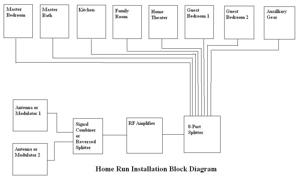
The Home Run System
Most residential installations are best served by the Home Run installation method. As previously mentioned, this required that each drop have a dedicated coaxial cable that runs directly to the demarcation or distribution point in the equipment closet. At the distribution point all these cables are connected to a distribution block or splitter. There are power splitters with a different number of output ports. However, all power splitters are built upon the basic one-to-two power splitter component. A one-to-four power splitter/combiner is made by cascading three one-to-two power splitters together. Inside a one-to-four power splitter, output ports of the first one-to-two splitter are connected to input ports of two other one-to-two splitters resulting in a total of four external output ports. Of course this means a 4-port splitter has twice the insertion loss of a 2-port splitter. In a similar manner, an 8-port splitter will exhibit at least three times the loss of a 2-port splitter. Beyond 8-ports splitters can seriously compromise signal levels without proper amplification. Each splitter component drops the signal at least -3.5dB.
In a typical residential installation there will likely be full use of 8-ports. From the antenna there will be one drop to the theater TV tuner, and perhaps a second to an FM tuner and a third to a DVR. Assuming three bedrooms we have used 6 of the available 8-ports. Add a television in the kitchen and, perhaps another in the master bath, den or home office and we’ve reached our allotment of connections. One problem that frequently arises is the issue of multiple drop placements in a single room or zone. Do those all need to be home-run? The answer is no; we can use a hybridized system of taps and home run for such a situation. See below for details on trunk and hybrid designs.
At this point we have a single coaxial cable input that has our antenna and satellite (or locally modulated sources) in one hand and eight cables running to various rooms in the other. How do we connect the ends? The 8-port splitter is the obvious answer, but signal attenuation caused by insertion of the devices themselves, as well as cable-induced roll-off, must be taken into account.
Understanding RF Signal Levels and Trunk Runs
Signals in cable systems are measured in dB relative to 1 mV(millivolt) across the 75 Ω characteristic cable impedance. Expressed in dBmV (decibel-millivolts), the minimum room-temperature noise (noise-floor) in a perfect cable system is -59dBmV. Ideally we need to deliver at least 0 dBmV of signal, but no more than +10dBmV, to the terminal on the television receiver. Lower numbers produce snowy pictures and higher numbers may overload the television receiver’s tuner, resulting in cross modulation of the channels.
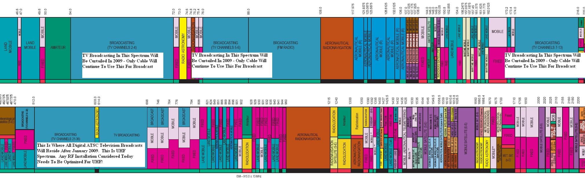
There are two types of signal attenuation that must be considered in a successful RF installation; flat power loss and roll-off. Flat power loss occurs when a device is inserted in the signal path and power is lost at all frequencies more-or-less equally. Roll-off is a function of cable length and frequency. Looking at the latter first, 100 feet of quality RG-6u will exhibit about 8.5dB of signal loss at 800MHz (in comparison, RG-59u will suffer nearly 50% greater signal loss at this frequency and length). A 100 foot straight run in a residential installation isn’t that unusual, so let’s use that as a starting point for our calculations. To have the higher numbered UHF stations display the same picture quality as the lower frequency VHF signals (keep in mind OTA VHF broadcasts are slated to be curtailed by the FCC by 2009, leaving all OTA television broadcast within the UHF spectrum) we need to add 8.5dB of tilt compensation just to prevent losses from the wiring used.
Now let’s look at flat power loss. If we are using a 1-in-8-out splitter we can expect at least -10.5dB per port signal loss. Assuming we have a good antenna installation in a strong signal area, and the combined signal after the diplexer is +3dBmV, we’ll need minimum of 7.5dB to a maximum of 17.5dB in additional gain (amplification) to deliver a signal in the specified range of 0 to +10dBmV at the drop location. Additionally we’ll need at least 5.5dB in tilt compensation for the cable loss. For this hypothetical installation we might select a flat 15dB VHF/UHF amplifier that features a tilt compensation control to peak the highest frequencies for the best reception. Clearly it is important to be able to measure our starting signal and balance the power at each stage of signal manipulation. There is no way to design and install and effective RF distribution system without knowing the real amplitude of our signal components!
There are additional considerations, which are beyond the scope of this particular article, which must be taken into account to maximize performance. It is vital to determine maximum and minimum signal input levels for distribution amplifiers based on amplifier gain, amplifier noise figures, and CTB (composite-triple-beat) performance parameters. Additionally, the potential for signal splitting to multiple devices at the terminal location of the network should be anticipated. Finally it is vital that any good RF distribution design take into account eminent signal introduction. Digital ATSC signals broadcast on the UHF band will soon become the standard. Systems designed only for maximum VHF or cable band performance will likely suffer when the user attempts to distribute these new signals. A complete accounting of all system variables and a written table summarizing the starting and ending actual and theoretical signal levels is invaluable documentation of system performance that will aid in future system expansion.
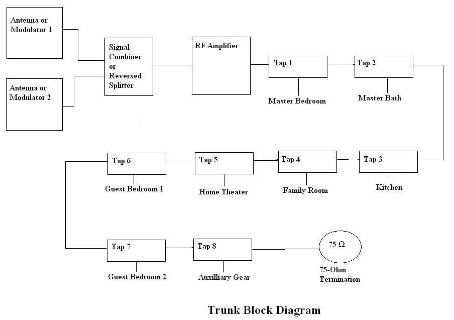
The Trunk-Run System
A trunk-based distribution system is what a cable plant creates to distribute signals to subscriber homes. We can emulate the same system within the context of a residential installation. In this type of installation a main trunk line is created and RF taps are used to provide each individual drop. The advantages include minimizing installation labor and cable use as only a single coaxial cable is capable of serving a full zone of drops. As an example, let’s assume a residential installation in a home with three floors. We can run one coax to each floor and then run taps off this trunk to provide drops to each access location. So if there are three bedrooms and two bathrooms on the upper floor, and we want to provide TV access in each bedroom plus the master bath, we can run one coax from the equipment closet to the first floor, then from the first floor to the upper floor.
In a trunk system, splitters are not used to divide the signal. Instead a directional coupler is used. A directional coupler has much less insertion loss than a splitter, on the order of 1.5dB. But a directional coupler (tap) has much higher loss to the drop location, as much as 9dB or more. This allows us to create a single master trunk line using a coaxial cable like an RG-8u that exhibits much less loss per foot than either RG-6u or RG-59u. Lower frequency-based attenuation means fewer issues with tilt and a flatter overall loss. This is much easier to control in a large system.
Let’s examine what such a system would look like if we had the same starting conditions as the example above. Signal levels are +3dB from the multiplexer and we have 8 drops on three floors. The longest distance to the top floor is 100 feet. RG-8u exhibits about 6.5dB of loss over 100 feet, but for such a short run we’ll stick with the RG-6u also used in the example above.
Now instead of having 8 wires coming into the equipment closet from the drop zones we only have one. Coming out of the amplifier we’ll run to the first tap, which will have four outputs at -12dB. From the output side of this tap we’ll run our trunk to the first floor of the home where we might have an additional 4 drops. We’ll then continue the same cable to the top floor for an additional 4 drops. The final tap will be closed with a 75
Ω termination to hold the characteristic impedance of the system. Also, it is very important to use a 75 Ω termination on each unused tap location to maintain characteristic system impedance at 75 Ω.Our losses in this system look like this: (+3dB initial signal level) + (-8.5dB attenuation) + (-12dB flat loss per drop) = -17.5dB system loss. We can easily add a 20dB amplifier to compensate for these losses and provide a +6dBmV signal to each drop location. If the longest run is 100 feet, but the average run for all drops was 60 feet, we may have just saved 300+ feet of RG-6u plus the time needed to install it. The drawback? Each drop will always have the same signal content. There is no way to isolate a single drop to change the system configuration in the future. You’d better get it right the first time if you’re designing a trunk-based system!
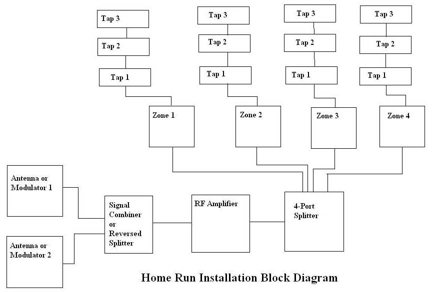
The Hybrid System
Compromises almost always provide the best return on investment and there's no surprise that that's true here. A hybrid installation would combine both a star topology and linear trunks to create an installation where identified "zones" are individually home run, but multiple drops in each zone minimize installation labor and materials. A good example of a system like this would be our hypothetical three-floor house where a home run cable comes from each floor to the distribution location. Now each floor might have a dozen or more taps providing MATV access on each wall of every room for maximum flexibility in the placement of furniture and electronics. At the same time each floor can be given unique attributes. The home theater may even be considered its own zone with taps feeding all the devices associated with the theater gear. Perhaps you'll have both cable services and satellite in the theater, but only cable to the rest of the zones. Maybe you'll enlarge the capability of the system from the original 8 drops anticipated to 36 drops covering every future lay-out and option you can think of. Now you’ll have truly scalable infrastructure that can service all your plans, now and in the future.
A sales and marketing professional, Joe holds degrees in Electrical Engineering and in Applied Business. He has been honored several times within the consumer electronics industry, being selected to serve as a judge for the prestigious Consumer Electronics Association "Mark of Excellence Awards" and having served on the Board of Directors of the Satellite Broadcasting and Communications Association.
View full profile