Helmholtz Resonant Absorber
1. Introduction.
A listening room, defined by its dimensions, can be mapped in terms of a series of pressure peaks and nulls, in all three dimensions. This refers to the creation of standing waves (modes), and the resultant sonic characteristic of the room at modal (essentially bass) frequencies. There are other considerations, such as the boundary effect, but this has less to do with specific modal treatment, and more to do with generalised treatment, and certainly with loudspeaker and listening position placement.
The problem with modal treatment comes in dealing with the very large wavelengths associated with modal frequencies. The provision of absorption at these frequencies, by simple absorptive panels of Rockwool or fibreglass, is not practical given the huge material depth required to provide pretty average levels of absorption. Even at 100Hz the depth of material required is:
1120 being the speed of sound in feet/second (ft/s) and 4f being 4 x the target frequency.
This means that a more dimensionally modest, and hence complex means of low frequency absorption is required. The three common means of providing such are the tube trap, the resonant panel (or membrane), and the Helmholtz resonator. The first two provide a comparatively wide operational bandwidth; at varying levels of absorption, and are particularly useful for generalised treatment. The Helmholtz resonator is very much function (frequency) specific. The narrow bandwidth of operation makes it ideal for treating single frequency anomalies.
The designation 'Helmholtz' resonator comes from the German physicist Hermann Von Helmholtz (1821 - 1894), who mathematically derived their design frequency in order to study the harmonic content of complex sounds. As a means of providing ambient resonance, simple resonators considerably pre-date Helmholtz, and are know to have been used in ancient Greek theatres. As a means of providing absorption by resonance, resonators were used in many early churches - from simple ash or fleece-filled jugs, and more latterly to specially designed walls or other structures, which remain in use today.
2. Calculations.
The often used, yet still appropriate analogy of an Helmholtz resonator is that of blowing across the top of a bottle - doing so yields a monotonic sound at the resonant frequency of the bottle. Taking the analogy a little further, the neck of the bottle represents the port, and the body of the bottle the cavity or enclosure.
Those familiar with ported loudspeaker/subwoofer enclosure design will understand the relationship of port area to enclosure area in terms of tuning (F B ). This is often referred to as the tuning frequency, but could also be called the Helmholtz frequency. The formula for calculating the resonant frequency of a Helmholtz resonator is:
![[formula2]](../../../images/formula2_th.gif/image)
![[formula3]](../../../images/formula3_th.gif/image)
Where f is the resonant frequency (Hz), c is the speed of sound (1120ft/s), p =3.14, S is the area of the port (ft 2 ), L is the length of the port (ft), and V is the cavity volume (ft 3 ).
Note the requirement that the units of measurement are constant. The example uses feet, but could be substituted for meters. Despite the simplicity of the equation there are many measurement variations that the designer will face. Therefore, it is highly recommended that the equation be programmed into a spreadsheet, allowing the designer to see instantly the effect each measurement change has on the design. The following Excel spreadsheet includes such calculations (including port end-correction), as well as a basic axial room mode calculator, which is useful for initial room mode mapping.
http://www.apsalisbury.dsl.pipex.com/modecalc.xls
Excited by a frequency relative to it's tuning, the air mass in the port tries to leave. It's motion, in turn, lowers the pressure of the air mass in the enclosure - which consequently attempts to draw the port's air mass back into the cavity. These motions are, naturally, lossy - the activating frequency (which, in reality, is a room mode), in perpetuating these motions, itself becomes lossy - hence the absorbent action.
2.1 Port end-correction.
The Helmholtz resonator is a narrow-bandwidth device, designed and used to target specific single frequency anomalies. The margin for design or constructional error, therefore, is minimal. One area often overlooked is that of port end-correction, without which a design may be rendered ineffective. Basically speaking, the air immediately outside either end of the port acts in sympathy with the design air mass in the port. This has the effect of increasing the apparent length of the port (fig1), and hence affects the tuning frequency of the resonator.
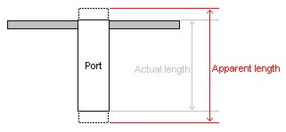
Fig1.
The apparent increase in port length is calculated as 0.732 x the port diameter (for a flush-fitted port, with little or no flare). Naturally, then, any shift in design frequency is connected to the diameter of port used, as well as to the cavity volume, in consequent calculations. At the volumes likely, and with a 3" - 4" port, the uncorrected resonant frequency will be off (high) by around 10Hz - 15Hz. Which in real terms is sufficient for the device to lack proper excitation by the target room mode, and hence prove ineffective.
Where f is the resonant frequency (Hz), c is the speed of sound (1120ft/s), p =3.14, S is the area of the port (ft 2 ), L is the length of the port (ft), D is the diameter of the port (ft), and V is the cavity volume (ft 3 ).
Modified to include port end-correction the formula elicits a marked change in resonant frequency. For so function (frequency) specific a device, it is vital that port end-correction be taken into account.
3. Design.
The fundamental design is an enclosure, or cavity, into which there is a vent, or port. The dimensions of these two areas are critical in that combined they determine the resonant frequency of the resonator. The shape of the cavity itself has a function, in that a smooth round cavity has very little frictional loss. This leads to a resonator that is highly absorbent over an ultra-narrow bandwidth, perhaps only really effective at the centre frequency - and equating to a very high Q (centre frequency divided by bandwidth). A square or rectangular cavity with angled intersections has frictional losses that reduce effectiveness in favour of an increased bandwidth, and equating to a low Q (relatively speaking). A good compromise is the tube, which retains performance over a useable bandwidth.
It should be borne in mind that by useable (which of course depends on the application and the end-user), non-damped resonators still only have worthwhile losses over perhaps 5Hz or 10Hz either side of the centre frequency. This can be increased, at the expense of reduced absorbent effect, by adding designed frictional losses in the form of cavity or port wadding. These design variables allow for fine-tuning, which is an essential part of passive acoustic treatment.
In terms of practical design, the basis of the project was a calculated room mode at 62Hz (the above calculations being based on the dimensions of the finalised design, after test measurements and tuning). Not a stacked mode, but one disparate from the neighbouring (upper) mode by some degree. Initial fine tuning in terms of frequency selection were performed using a combination of test tone sweeps and single frequency test tones, measured using a Radioshack SPL meter. Important in any area of hifi, including acoustical treatment, measurements were combined with music listening tests (although a problem area had been identified previously, and was the causation of the project).
Helmholtz Resonant Absorber - page 2
3.1 Construction.
The combination of absorbent performance and bandwidth makes a tube the ideal basis for a resonator cavity. Even modest side-walls will ensure absolute rigidity, and completion of the enclosure requires just two end-caps. The material for the cavity is left to the end-user, but products such as concrete pile forming cardboard tube are ideal, as is underground construction-grade PVC tube - as used in this project (fig2).
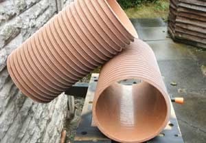
Fig2.
The only requirement of the tube is that it be sized according to design requirements. Bearing in mind that the required volume comes from internal measurements - side-wall and end-cap thickness need to be taken into consideration, as does the displacement of the port and any internal bracing. **nb: if tube dimensions appear compromised, remember that adjustments can be made to the port to achieve the desired resonant frequency .
It is critical that the finished enclosure be sealed properly, hence the need for accuracy with end-cap sizing. Time spent measuring the diameter of the tube, and in creating templates (fig3) is time well spent. Initial measurements are best done on paper, and transferred to stiff card or hardboard. Material for the end-caps is again left to the end-user, but MDF is a practical and workable material. Marked using the template, cut out and fine-sanded for a good friction fit, this initial end-cap can be used as a template for a bearing-guided router blade (fig4). Even a modest router in this situation will save considerable time and give a repeatable good quality finish.
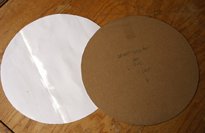
Fig3.
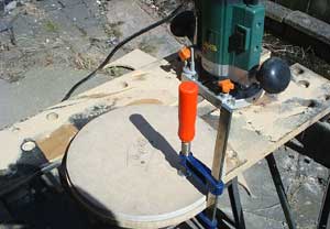
Fig4.
There are many types of piping that will substitute as a port for the resonator. For resonators designed to be used at very low frequencies a minimum diameter of 2" should be considered - and be of sufficient side-wall thickness that it does not readily collapse. This project uses 68mm (2.7") PVC downspout piping, which fills the criteria, and is extremely cost effective - sufficiently so that cutting several lengths for tuning purposes (fig5) adds little to the overall project cost.
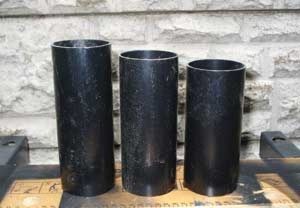
Fig5.
The cut-out for the port in the end-cap follows pretty much the same requirements for sizing the end-cap - making sure it has a good friction fit. The end-caps can now be sealed into place, using a strong PVA-derived adhesive, or an epoxy resin. At this time the port should remain free, for initial tuning purposes. When tuning is completed, and resonant frequency selected, the chosen port can be sealed into place using the same adhesive as the end-caps. Choice and level of finish is left to the end-user (fig6).
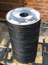
Fig6.
3.2 Tuning.
For a device so function specific, tuning should be irrelevant. Indeed, as far as mapping the room, finding problematic frequencies, and designing the resonator to suit, it is. As ever, though, the devil lies in the detail, and there are performance aspects that are difficult to gauge prior to objective assessment. Two primary examples are placement, and resonator bandwidth (through the design addition of acoustic wadding).
Placement ideally goes hand in hand with final tuning of the resonant frequency. It is often quoted that you should use the room corners for placement. Yet, whilst the intersection of room boundaries at corners guarantees modal action, it is often too simplistic an option. Given the effect that room shape, furnishings, other acoustical treatments, and the audio system have on response, measurement is the only accurate indicator of placement. Using an SPL meter and a series of single frequency test tones, one can begin to gauge the effect of the resonator allied to the response at varying points in the listening room
Despite being presented here as separate issues, the tuning process is a whole - each element having an effect on the other. If there is a central, predominant issue, then it is the bandwidth of the resonator and the level of frictional loss introduced. From the outset the aim of this project was to remove as much of the target mode as possible, i.e. elicit the greatest loss (absorption) from the resonator. Under SPL meter and test tone assessment this was easily realised, yet subsequent music listening tests proved unsatisfactory.
Initially, the resonator quite audibly added to the problem it was designed to remove - by increasing resonance, allowing the target mode to sustain, or ring. The problem with the mode, then, was not primarily of level, but of resonance. Widening the operational bandwidth of the resonator, with a modest amount acoustic wadding inserted into the cavity, reduced its relative absorptive effect, but had a marked impact on the problematical resonance. With hindsight, and the use of acoustical software to measure spectral decay (waterfall plot), the design requirements may well have been different - same end, different means.
As a sidebar, and a precursor to the project measurements, it should be pointed out that the resonator, in fact the room itself, has a response that is entirely dictated by the excitation of resonant frequencies. That a room can support certain modal frequencies does not mean that they are activated by the audio system. The flip side, then, is to consider that modified excitation from the audio system (a change of loudspeakers, or a significant change in output level), or from a home cinema system (which often feature high levels of very low bass), will affect the modal response of the room, and the resultant effect of the Helmholtz resonator (fig7) on it.
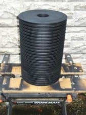
Fig7.
4. Measurements.
The project resulted in two identical Helmholtz resonant absorbers, now tuned (after the design addition of acoustic wadding to increase bandwidth) to about 60Hz. The following results are the final sets taken, and those now being used in the target listening room. The first set being those from the primary (hifi) loudspeakers, and the second set from the home cinema subwoofer - the differences in response are marked, and highlight the effect that frequency response and level of low bass (particularly) have on room response.
Bear in mind that the results for the primary hifi system, the one around which this project was based, shows smooth, but quite subtle losses - the primary benefit of decreased resonance is not shown. As with many, if not all passive acoustic treatments, it may be necessary to use additional units to produce the desired response.
4.1 Measurement notes.
Each run of measurements has an initial set and a control set. As the measurements were for comparison purposes, not specific SPL levels, care was taken in the provision of a control set to reduce spurious readings or read errors. The results were entered into an Excel spreadsheet and an average taken between the two sets of measurements. The averaged results are those used in the following graphs.
All measurements were taken using an analogue Radioshack SPL meter, using single frequency test tones.