
Velodyne SC-IW In-Wall Subwoofer System Review
Velodyne SC-IW In-Wall Subwoofer
- Product Name: Velodyne SC-IW In-Wall Subwoofer System
- Manufacturer: Velodyne
- Performance Rating:


- Value Rating:
- Review Date: July 26, 2007 20:00
- MSRP: $ 999/each Total system price as reviewed $2997
| Woofer: | 4"
x 14" rectangular driver (3" x 13.25" piston dimensions) |
| Frequency
Response: (+/- 3 dB) |
22 - 120 Hz |
| Harmonic Distortion: | <5% (typical) |
| Magnet Structure: | 275 oz. Neodymium motor structure |
| Voice Coil: | 3" Dual Layer inner/outer wind |
| Video Shielded: | Yes |
| Product
Dimensions*: (H/W/D) |
28
¾" x 14" x 3 3/8" (73 x 35.56 x 8.57 cm) Enclosure (only): 19" x 14" x 3 3/8" (48 x 36 x 8.6 cm) Driver (only) 10 ½" x 14" x 3 ¾" (27 x 36 x 9.5 cm) |
| Cabinet: | Sealed enclosure |
| Warranty: (parts/labor) |
Two years |
| Shipping
Weight: (approx) |
2
Cartons: Carton 1: 16 lbs (7.25 Kg) Carton 2: 27 lbs (12.25 Kg) Total: 43 lbs (19.5 Kg) |
| Grille
Options: (Both Included) |
Standard Grille: 17.0" x 13.8" (43.2 cm x 35
cm) Designer Grille: 18.0" x 4.64" (45.7 cm x 11.8 cm) |
| SC-1250 Amplifier | |
| Amplifier: (Class D) |
3000
watts Dynamic 1250 watts RMS Power |
| High Pass Crossover: | 80 Hz (6 dB/octave) |
| Low Pass Crossover: | 30 Hz - 160 Hz, Defeatable, 24 dB/octave slope |
| Inputs: | Line and Speaker Level |
| Outputs: | Line-level,
80 Hz up Speaker level for up to two subwoofers |
| Phase: | 0°, 90°, 180°, 270° |
| Dimensions
(H/W/D): (includes feet) |
4
¼" x 17.0" x 13.0" (10.8 x 43.18 x 33.02 cm) **Allow two extra inches in depth for wire connectors and detachable power cable. **Includes feet. Feet can be removed for rack mount use. Unit is approximately "two rack units" high. |
| Warranty: (parts/labor) |
Two years |
| Shipping
Weight: (approx) |
30 lbs (13.6 Kg) |
Pros
- What Professional Designers & Architects Dream About
- Superb Build Quality
- The Best In-Wall Subwoofer We Have Heard To Date
- Very Easy to Install in New Construction Homes
Cons
- Global Phase Control
- Relatively Short 3-Year Warranty
- Dry-wall Mud Won’t Adherer To Filler Panel
- Inaccurate Wiring Info In Installation Guide
- May Be Difficult to Install In Retro Custom Installations
Introduction
 Today’s modern interiors and trendy
designs are minimalist and unobtrusive. Décor, furniture and accessories are
kept sleek and small with the focus on the room as a whole. Open interior
designs are meant to flow and show off the expansiveness of the entire living
area. Incorporation of high- end multi-media systems into the modern interior
design often leads designers and home owners toward in-wall/in-ceiling based
speaker systems for home theater. In-wall based speaker systems, although aesthetically
pleasing have not been recognized for their performance attributes. Manufacturers
have been working very hard to overcome the limitations of in-wall speaker
systems and have recently made great strides in performance. Anyone that has
experienced a decent multi-channel home theater system recognizes the
importance of the subwoofer for reproducing the LFE channel; but, how do you
incorporate a huge box subwoofer into a minimalist interior design? Well, the
short answer is you don’t; unless you deviate from the overall design plan.
In-wall subwoofers are a relatively new alternative that fit nicely into the
minimalist interior design. However, due the installation criteria, we haven’t
heard one that truly offered high end multi-channel performance. When we heard
that Velodyne introduced a new in-wall subwoofer we were curious to see if this
highly regarded subwoofer manufacturer could solve the performance deficiency
problems associated with most in-wall subwoofers.
Today’s modern interiors and trendy
designs are minimalist and unobtrusive. Décor, furniture and accessories are
kept sleek and small with the focus on the room as a whole. Open interior
designs are meant to flow and show off the expansiveness of the entire living
area. Incorporation of high- end multi-media systems into the modern interior
design often leads designers and home owners toward in-wall/in-ceiling based
speaker systems for home theater. In-wall based speaker systems, although aesthetically
pleasing have not been recognized for their performance attributes. Manufacturers
have been working very hard to overcome the limitations of in-wall speaker
systems and have recently made great strides in performance. Anyone that has
experienced a decent multi-channel home theater system recognizes the
importance of the subwoofer for reproducing the LFE channel; but, how do you
incorporate a huge box subwoofer into a minimalist interior design? Well, the
short answer is you don’t; unless you deviate from the overall design plan.
In-wall subwoofers are a relatively new alternative that fit nicely into the
minimalist interior design. However, due the installation criteria, we haven’t
heard one that truly offered high end multi-channel performance. When we heard
that Velodyne introduced a new in-wall subwoofer we were curious to see if this
highly regarded subwoofer manufacturer could solve the performance deficiency
problems associated with most in-wall subwoofers.
Description
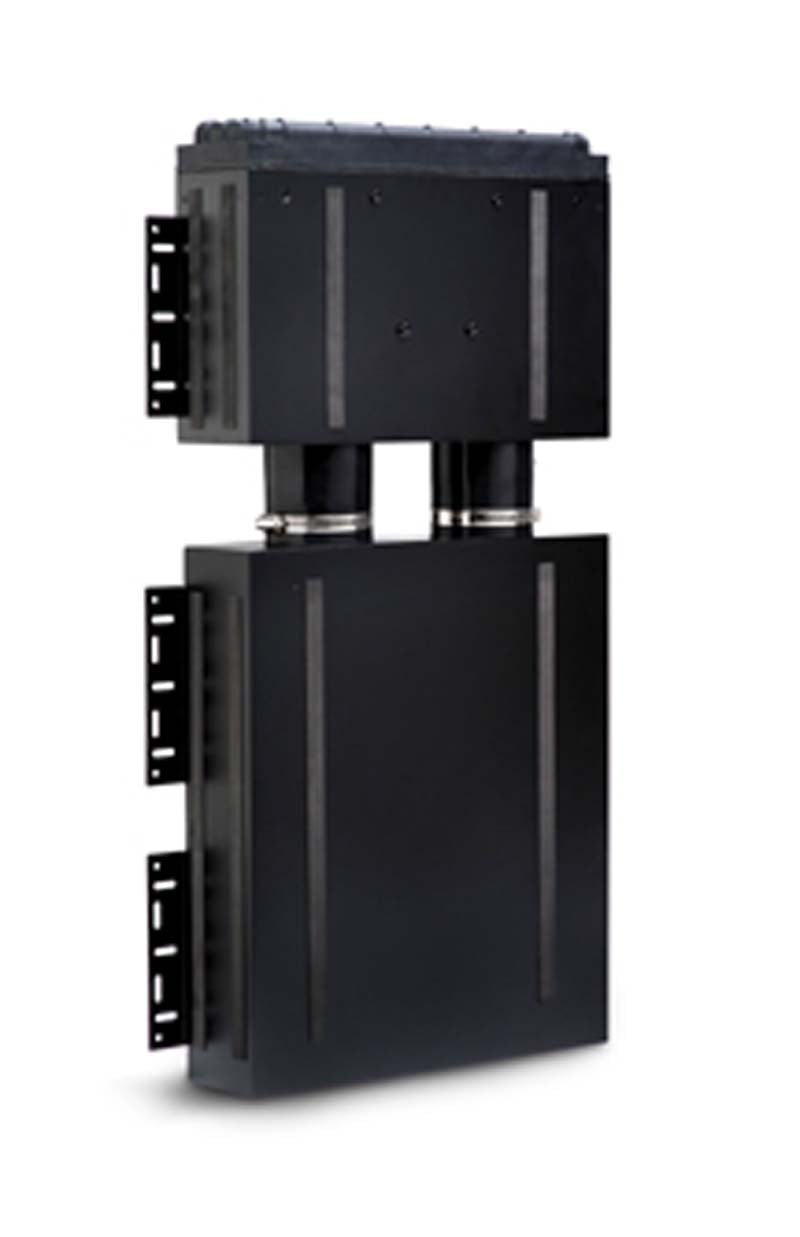
Velodyne’s SC-IW in-wall subwoofer is a radical
departure from previous in-wall subwoofer designs. The unique 2-piece sealed
enclosure design fits flush in a typical 2x4-16-inch on center studded wall.
The subwoofer’s high excursion (1-inch peak X-max) T shaped driver fires
vertically and the manufacturer claims performance characteristics rivaling
10-inch high end free standing woofers. Once installed and wired, the woofer
enclosure is covered with sheetrock. Only the small unobtrusive grill reveals
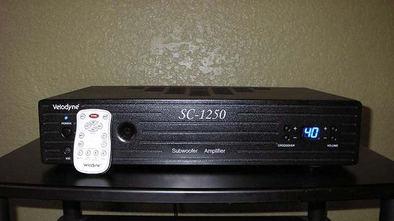
its location. The SC-IW is a passive subwoofer requiring separate amplification
and for this purpose Velodyne has the optional SC-1250 amplifier. The rack
mountable amplifier features 3000 watts of dynamic power/ 1250 watts RMS. Other
features include sophisticated DSP control, built in test tone generator,
7-band automatic room equalizer, 12-volt trigger, IR repeater jack, RS-232 port for remote systems, and
pre-programmed remote control. The amplifier can easily power two of the SC-IW
subwoofers.
Configuration and Installation Considerations
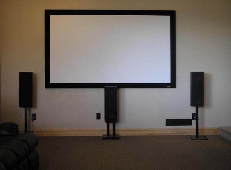
 Taking my room dimensions and floor plan into
consideration and after receiving some very informative consultation from
Velodyne, I decided to order two SC-IW subwoofers and one SC-1250 amplifier. My
family room is not an uncommon layout but as described later in the review, it
did pose some unexpected installation concerns. The size is about average with dimensions in feet
of 12 wide x 24 long x 9 high or about 2592 CU^3. The primary listening
position is about 12 feet back from the front wall. The front right side of the
room is open to an adjacent room and the back of the room has a large floor to
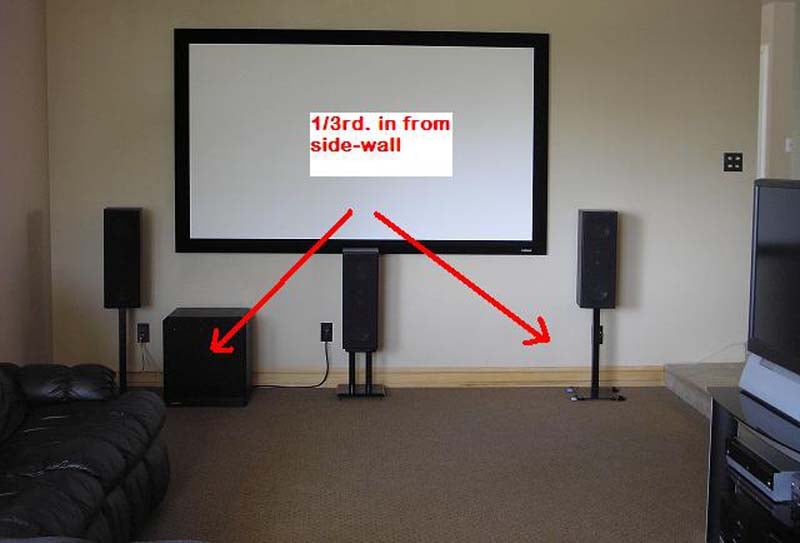
ceiling fireplace. My initial plan was to install the SC-IW subwoofers
approximately 1/3-rd in from the sidewalls on the front wall. I currently have
a Velodyne HGS-15X installed on the front wall about 1/3 in from the sidewall
and have found this location to be optimal in my room for smooth low frequency
performance.
Taking my room dimensions and floor plan into
consideration and after receiving some very informative consultation from
Velodyne, I decided to order two SC-IW subwoofers and one SC-1250 amplifier. My
family room is not an uncommon layout but as described later in the review, it
did pose some unexpected installation concerns. The size is about average with dimensions in feet
of 12 wide x 24 long x 9 high or about 2592 CU^3. The primary listening
position is about 12 feet back from the front wall. The front right side of the
room is open to an adjacent room and the back of the room has a large floor to
ceiling fireplace. My initial plan was to install the SC-IW subwoofers
approximately 1/3-rd in from the sidewalls on the front wall. I currently have
a Velodyne HGS-15X installed on the front wall about 1/3 in from the sidewall
and have found this location to be optimal in my room for smooth low frequency
performance.
Installing the SC-IW subwoofers in a new construction home after completion of framing and rough electrical is so easy even a Neanderthal could do it! Simply pick a suitable location, install the enclosure, pre-wire, finish and you’re done. Retro custom installations, homes that are already built, require meticulous planning and a high degree of installation knowledge. Pre-built homes can have hidden obstacles lurking in the wall, unraveling even the most thorough detailed plan provided by a professional custom installer. The bottom line with retro construction installations is if you don’t know what you are doing, leave it to a professional. The work can be daunting and even dangerous as you will find out in the next segment of this review.
SC-IW Installation Retro
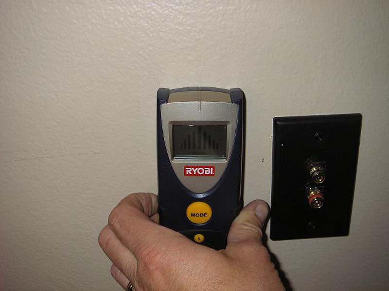
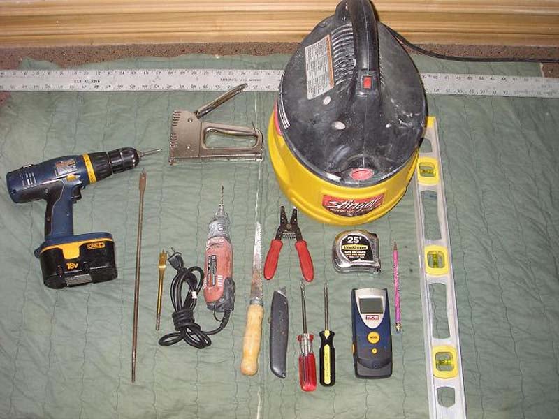 If you decide you are going to proceed with a retro
type installation, you are going to need some basic tools to perform the
installation. You will need: stud sensor (preferably one that also detects
electrical), tape measure, level, straight edge, utility knife, dry-wall saw,
corded or cordless drill, wood boring bits, wet vac and other assorted hand
tools. The use of a Roto Zip is optional for cutting dry wall. If you choose to
finish the sheetrock patches you will also need dry walling tools. The first
step is to find the location of the studs in the wall for the proposed location
of the subwoofer. Remember when I told you that even well prepared plans can
quickly unravel in retro-fit type installations? This is exactly what occurred
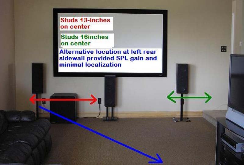
with my installation. When I marked out my stud framing using my stud sensor, I
discovered on the left side of the front wall the 2x4 stud framing was installed
13-inches on center and the right side of the wall framing was 16-inches on
center.
If you decide you are going to proceed with a retro
type installation, you are going to need some basic tools to perform the
installation. You will need: stud sensor (preferably one that also detects
electrical), tape measure, level, straight edge, utility knife, dry-wall saw,
corded or cordless drill, wood boring bits, wet vac and other assorted hand
tools. The use of a Roto Zip is optional for cutting dry wall. If you choose to
finish the sheetrock patches you will also need dry walling tools. The first
step is to find the location of the studs in the wall for the proposed location
of the subwoofer. Remember when I told you that even well prepared plans can
quickly unravel in retro-fit type installations? This is exactly what occurred
with my installation. When I marked out my stud framing using my stud sensor, I
discovered on the left side of the front wall the 2x4 stud framing was installed
13-inches on center and the right side of the wall framing was 16-inches on
center.
 The reason for the extra stud
framing on the left side became clear after looking in the attic and the back
of the wall. The wall is partially load bearing and has a stair case that runs
along the back of the wall. This framing technique is not as uncommon as one
would think. Over the many years I have been installing home theater systems, I
have discovered many different configuration and variants of framing in older
and even newer homes. Obviously the SC-IW subwoofer will not fit into a stud
cavity of 13-inches, so I had to come up with an alternate plan. Using my stud
sensor, I mapped out several alternate locations with stud bays of 16-inches on
center that would accommodate the SC-IW subwoofer. Not knowing how the
subwoofer would perform in the alternate locations, I decided to conduct an SPL
level test at different frequencies with the subwoofer freestanding in the
proposed newly mapped out locations.
The reason for the extra stud
framing on the left side became clear after looking in the attic and the back
of the wall. The wall is partially load bearing and has a stair case that runs
along the back of the wall. This framing technique is not as uncommon as one
would think. Over the many years I have been installing home theater systems, I
have discovered many different configuration and variants of framing in older
and even newer homes. Obviously the SC-IW subwoofer will not fit into a stud
cavity of 13-inches, so I had to come up with an alternate plan. Using my stud
sensor, I mapped out several alternate locations with stud bays of 16-inches on
center that would accommodate the SC-IW subwoofer. Not knowing how the
subwoofer would perform in the alternate locations, I decided to conduct an SPL
level test at different frequencies with the subwoofer freestanding in the
proposed newly mapped out locations.
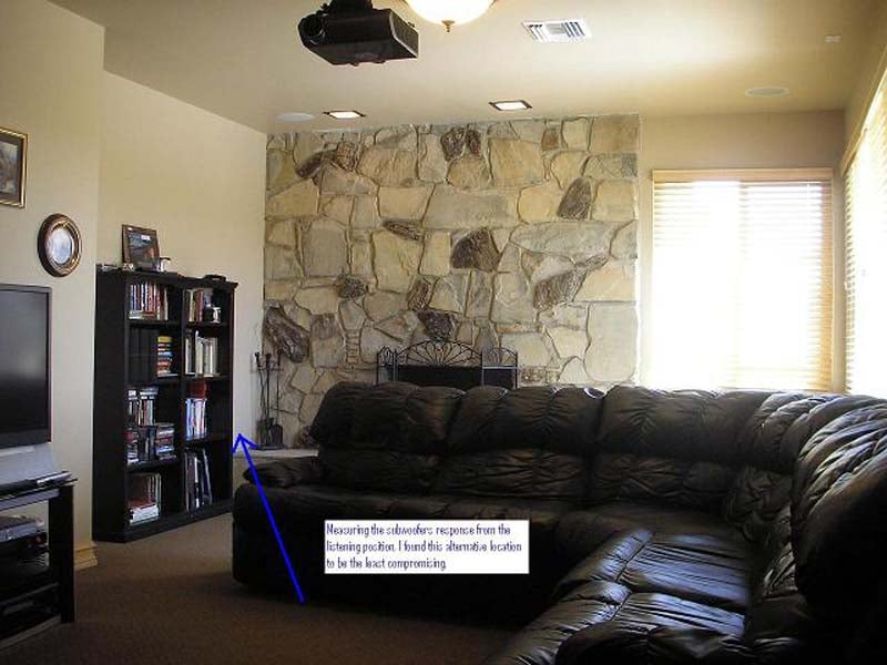
 At the conclusion of the test, I
found that installing the second subwoofer on the left wall at the rear of the
room close to the listening position provided a fairly smooth response with
little compromise in localization and SPL level gain. The installation
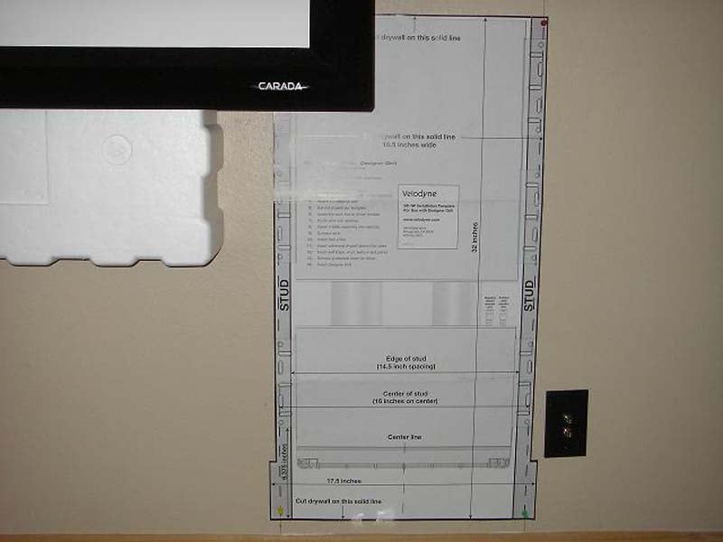
instructions provided with the Velodyne SC-IW are very easy to follow and cover
all aspects of installation for new and retro-fit installations. Once the stud
centers have been located, its time to use the supplied template and decide on
the grill type. The SC-IW has two grill options: standard grill provides easy
servicing of the driver but is a large square grill. The Designer grill is the
smallest grill available and is very aesthetically pleasing. The installation
method is about the same for both grill types, I decided use the small designer
grill.
At the conclusion of the test, I
found that installing the second subwoofer on the left wall at the rear of the
room close to the listening position provided a fairly smooth response with
little compromise in localization and SPL level gain. The installation
instructions provided with the Velodyne SC-IW are very easy to follow and cover
all aspects of installation for new and retro-fit installations. Once the stud
centers have been located, its time to use the supplied template and decide on
the grill type. The SC-IW has two grill options: standard grill provides easy
servicing of the driver but is a large square grill. The Designer grill is the
smallest grill available and is very aesthetically pleasing. The installation
method is about the same for both grill types, I decided use the small designer
grill.
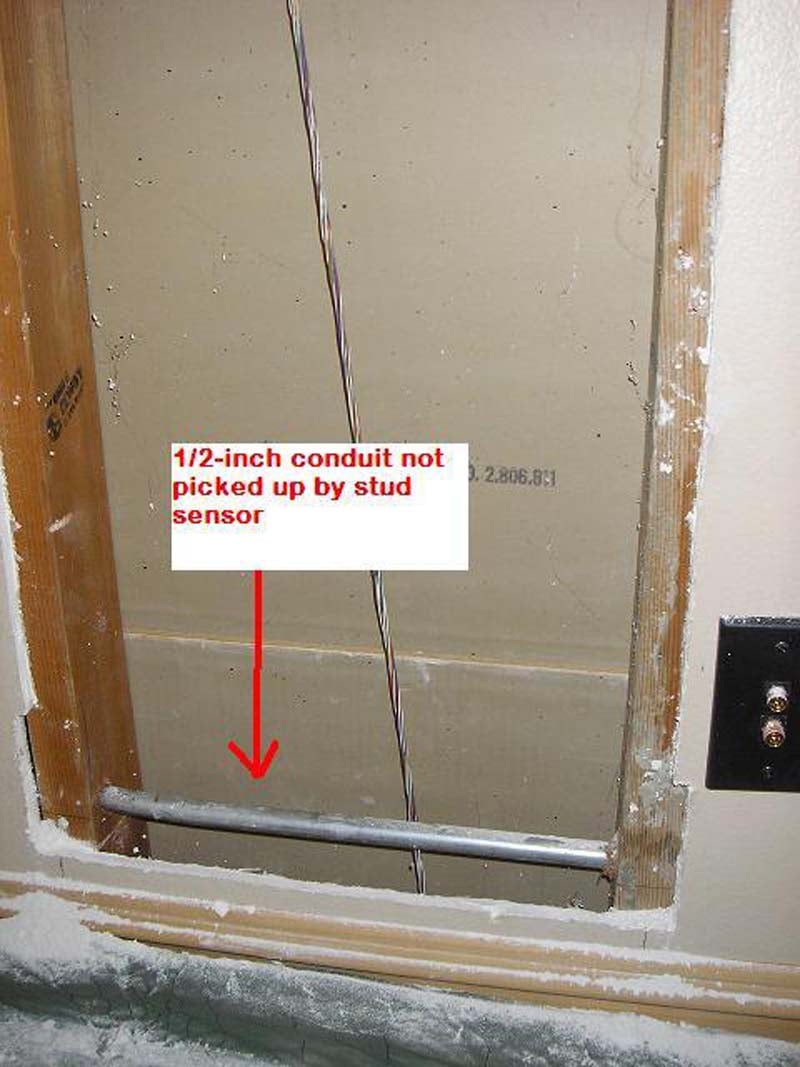
Securing the template to the wall and making sure it was level I marked
out the appropriate pattern for the designer grill. Using a straight edge you can score the
drywall with a utility knife for removal. Another option is to use a Roto Zip
which is much faster. If you use a RotoZip the use of a wet vac followed
closely behind the running bit will minimize dust. This is a little tricky to
do if you don’t have RotoZip experience so you may need a helper. When I
removed the 5/8-inch sheet rock that I cut out for the subwoofer, I was in for
another little surprise. The older less sophisticated stud/electrical sensor
that I was using did not sense the 1/2-inch electrical conduit installed in the
stud bay. This was yet another unexpected retro installation hurdle to over
come but this did provide me with an excuse to purchase a newer more
sophisticated sensor like the Ryobi that will detect electrical as well as
metal. I got lucky and this was a relatively easy fix because the conduit was
installed in the lower half of the stud bay. If the conduit had been installed
up higher I would have needed to patch the wall and find yet another alternate
location. The simple fix was to move the SC-IW subwoofers location up two
inches and patch the bottom of the wall.
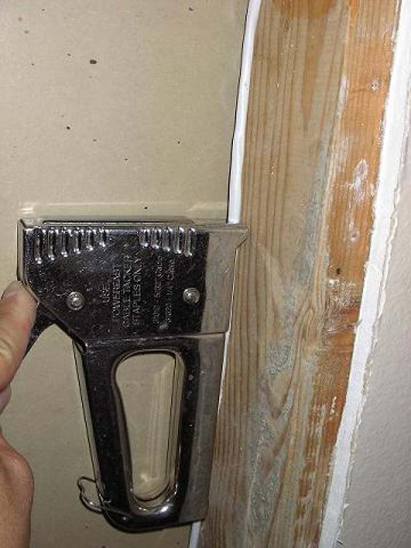
 Once the sheetrock is cut out, it should be relatively easy
to pre-wire to the subwoofer. The size of the cut out should provide you with
plenty of room to drill trough any blocking installed in the wall. The SC-IW
installation manual shows a picture of generic non in-wall approved speaker
wire installed in the stud bay. Do not use speaker wire like the one pictured
in the installation manual. All wire that is to be installed
in the wall should be rated for in wall installation and comply with the
National Electrical Code (NEC). Speaker wire approved for in wall installation
will typically be stamped with the designation UL approved CL2 or CL3. I
used 16-4 (13 AWG equivalence) in-wall wire with the four conductors doubled up
to make one twisted pair to each subwoofer.
The use of good 12-2 in-wall wire will work also. The wire should be attached
to the side of the stud bay so it won’t interfere with the enclosure
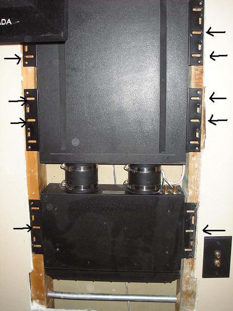
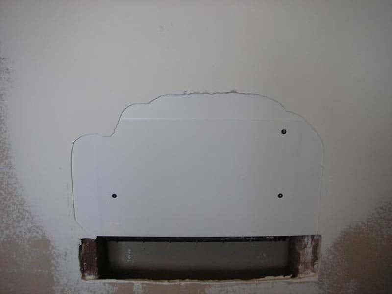
installation. Installing the enclosure is fairly straight forward: simply
terminate the speaker wire and screw the enclosure into the studs with the
provided screws. I marked the location of the oblong holes on the SC-IW
installation brackets to provide a location to screw through the dry wall into
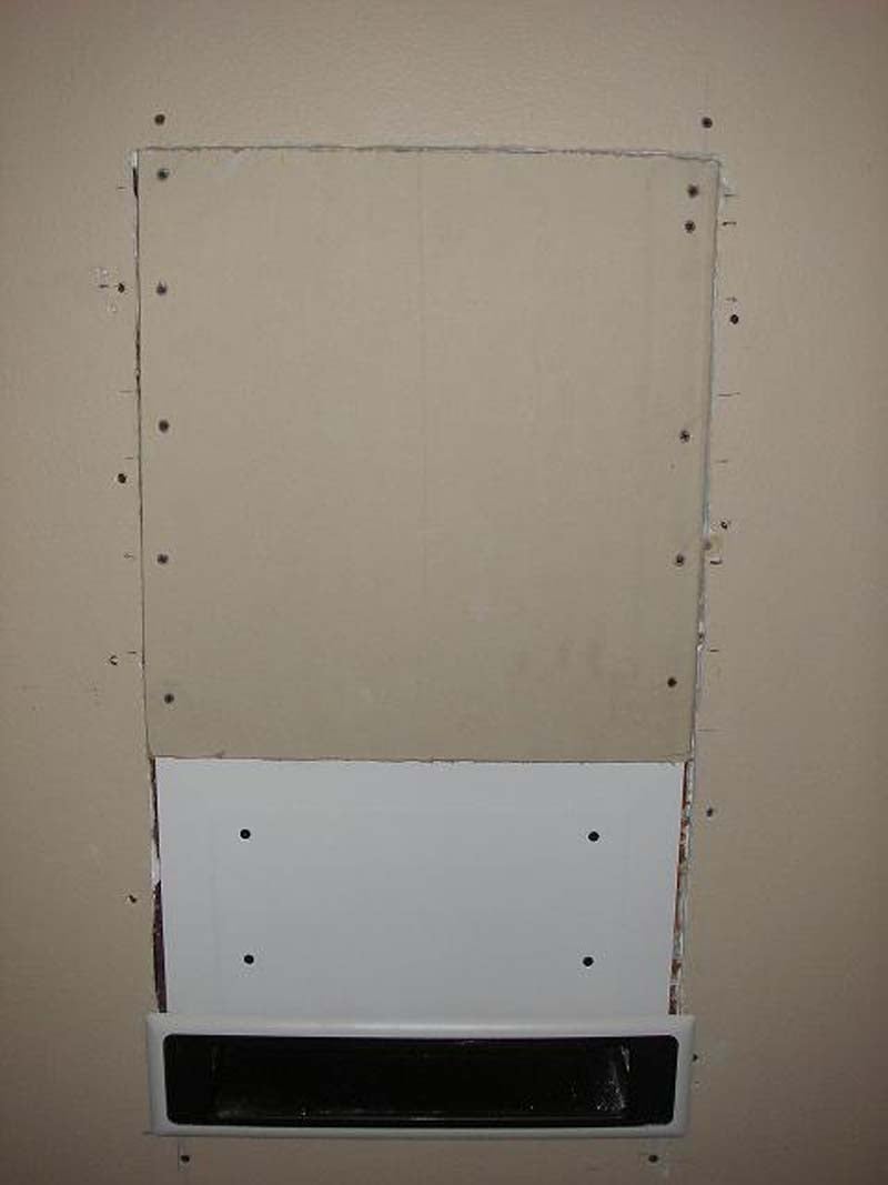
the stud missing the metal bracket. Once the enclosure is installed its time to install the new
sheetrock, filler panel and grill insert. Make sure to secure the existing
sheetrock to the studs before finishing. Now that the rough sheet rock patch is
installed, you can finish the dry wall patch. I chose to do my own drywall
patching and texture work but you may choose to hire a pro depending on your
skill level. One problem I discovered after the drywall compound dried was the
filler panel shipped with the SC-IW is very smooth and my first patch attempt
did not adhere to it after curing. This is partially my fault as I should have
noticed this before doing my dry wall compound patching work.
Once the sheetrock is cut out, it should be relatively easy
to pre-wire to the subwoofer. The size of the cut out should provide you with
plenty of room to drill trough any blocking installed in the wall. The SC-IW
installation manual shows a picture of generic non in-wall approved speaker
wire installed in the stud bay. Do not use speaker wire like the one pictured
in the installation manual. All wire that is to be installed
in the wall should be rated for in wall installation and comply with the
National Electrical Code (NEC). Speaker wire approved for in wall installation
will typically be stamped with the designation UL approved CL2 or CL3. I
used 16-4 (13 AWG equivalence) in-wall wire with the four conductors doubled up
to make one twisted pair to each subwoofer.
The use of good 12-2 in-wall wire will work also. The wire should be attached
to the side of the stud bay so it won’t interfere with the enclosure
installation. Installing the enclosure is fairly straight forward: simply
terminate the speaker wire and screw the enclosure into the studs with the
provided screws. I marked the location of the oblong holes on the SC-IW
installation brackets to provide a location to screw through the dry wall into
the stud missing the metal bracket. Once the enclosure is installed its time to install the new
sheetrock, filler panel and grill insert. Make sure to secure the existing
sheetrock to the studs before finishing. Now that the rough sheet rock patch is
installed, you can finish the dry wall patch. I chose to do my own drywall
patching and texture work but you may choose to hire a pro depending on your
skill level. One problem I discovered after the drywall compound dried was the
filler panel shipped with the SC-IW is very smooth and my first patch attempt
did not adhere to it after curing. This is partially my fault as I should have
noticed this before doing my dry wall compound patching work.
 Removing the installed filler panel, I used 60 grit
sand paper and acetone to roughen up the filler panel surface. This provided
the grip needed for the dry wall compound to adhere to the surface. With a wide
dry wall mud knife I applied a rough and finish coat of quick set dry wall
patching compound insuring each coat was dry before applying the next. Once the
finish coat was complete and dry, I proceeded to sand the patch until it was
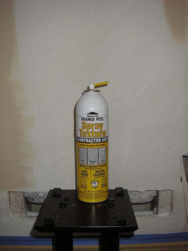
smooth and blended in with the existing wall. I used canned spray texture to
spray the texture coat finish onto the wall. This is available at most home
improvement stores and with a little patience and practice you can achieve
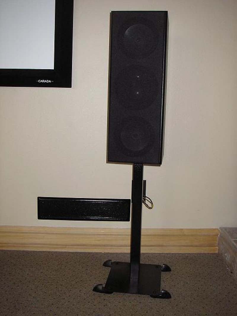
really great results. Installing the metal grill and painting the drywall patch
is the last step in the installation process. The designer grills are paintable;
you may choose to paint them the same color as your wall for a blended
appearance. I took a different approach and decided to highlight the grill with
gloss black paint to complement the rest of the black components in my system.
Removing the installed filler panel, I used 60 grit
sand paper and acetone to roughen up the filler panel surface. This provided
the grip needed for the dry wall compound to adhere to the surface. With a wide
dry wall mud knife I applied a rough and finish coat of quick set dry wall
patching compound insuring each coat was dry before applying the next. Once the
finish coat was complete and dry, I proceeded to sand the patch until it was
smooth and blended in with the existing wall. I used canned spray texture to
spray the texture coat finish onto the wall. This is available at most home
improvement stores and with a little patience and practice you can achieve
really great results. Installing the metal grill and painting the drywall patch
is the last step in the installation process. The designer grills are paintable;
you may choose to paint them the same color as your wall for a blended
appearance. I took a different approach and decided to highlight the grill with
gloss black paint to complement the rest of the black components in my system.
SC-IW Setup, Measurments and Analysis
 The SC-1250 amplifier
is extremely connection flexible and can be configured for just about any type
of installation. The most common approach would be to use your receiver’s LFE
subwoofer pre-output jack and connect it to the SC-1250’s LFE input. If your
receiver or processor handles the entire subwoofer crossover duties you can
disable the SC-1250's low-pass crossover to prevent cross over cascading. In my
multi-channel system, a subwoofer LFE cross over setting of 60-Hz worked best
and is the setting I used on my receiver setup for this review. The SC-1250
amplifier can control and power a variety of different subwoofers. The
amplifier needs to be programmed for the specific type of subwoofer installation;
this is achieved by powering up the amplifier while pressing any of the buttons
on the front panel. After the amplifier boots up you can choose SC-in-wall (IW), SC-in-floor
(IF), SC-in-ceiling (IC) or Generic Subwoofer (GS). Since this is an in-wall
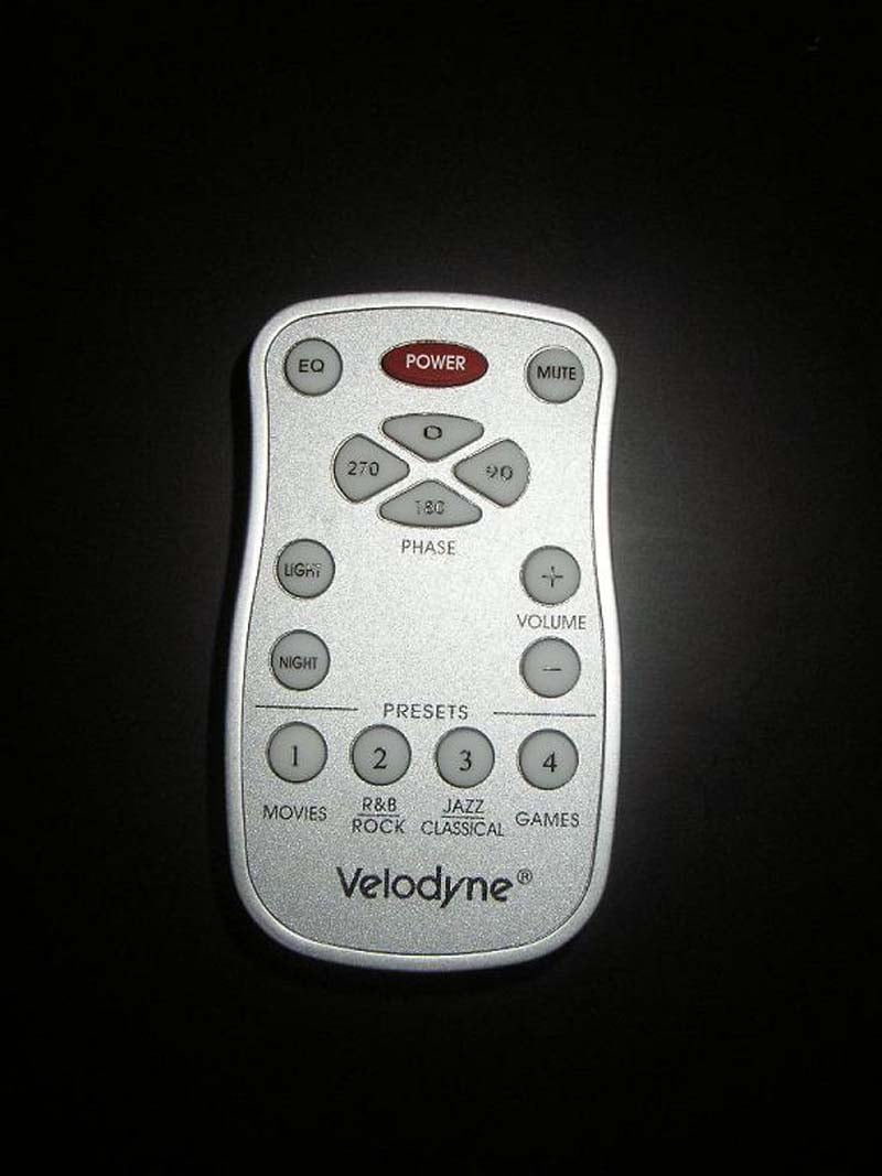
subwoofer the selection of the (IW) setting is the correct choice. Calibration
is very easy thanks to the remote included with the SC-1250 amplifier. I calibrated
the SC-IW subwoofers SPL to match the level of the speakers in my system using
my trusty Radio Shack SPL meter. The amplifier has an adjustable phase setting
of 0-90-180 and 270. The proper setting for the phase would be the setting in
which you hear or measure the most even bass at your listening position.
Unfortunately the phase setting is not independent for the two subwoofers and
is applied to both “A” and “B” subwoofer output speaker terminals on the
SC-1250 amplifier. I wanted to measure the response of the subwoofers with the
two subwoofers out of phase. I mechanically reversed the phase of one of the
SC-IW subwoofers at the amplifier’s subwoofer speaker terminal. Reversing the
phase effectively placed one of the SC-IW subwoofers 180 degrees out of phase.
After going through the multitude of phase settings with both subwoofers’ wire
in phase and out of phase, I found the best setting for the room to be both
subwoofers wired in phase and the amplifier phase setting at 0. Connecting the
small supplied omni-directional microphone and pressing EQ on the remote enables
the Automatic EQ program. The amplifier/subwoofer emits 12 “Sweep Tones” from
20-150Hz. After the amplifier completes and processes the measured information,
the amplifier returns to normal operation and is now configured for your room.
The SC-1250 has four preset EQ settings, for reference level the Jazz/Classical
level applies no EQ or Volume Differential.
The SC-1250 amplifier
is extremely connection flexible and can be configured for just about any type
of installation. The most common approach would be to use your receiver’s LFE
subwoofer pre-output jack and connect it to the SC-1250’s LFE input. If your
receiver or processor handles the entire subwoofer crossover duties you can
disable the SC-1250's low-pass crossover to prevent cross over cascading. In my
multi-channel system, a subwoofer LFE cross over setting of 60-Hz worked best
and is the setting I used on my receiver setup for this review. The SC-1250
amplifier can control and power a variety of different subwoofers. The
amplifier needs to be programmed for the specific type of subwoofer installation;
this is achieved by powering up the amplifier while pressing any of the buttons
on the front panel. After the amplifier boots up you can choose SC-in-wall (IW), SC-in-floor
(IF), SC-in-ceiling (IC) or Generic Subwoofer (GS). Since this is an in-wall
subwoofer the selection of the (IW) setting is the correct choice. Calibration
is very easy thanks to the remote included with the SC-1250 amplifier. I calibrated
the SC-IW subwoofers SPL to match the level of the speakers in my system using
my trusty Radio Shack SPL meter. The amplifier has an adjustable phase setting
of 0-90-180 and 270. The proper setting for the phase would be the setting in
which you hear or measure the most even bass at your listening position.
Unfortunately the phase setting is not independent for the two subwoofers and
is applied to both “A” and “B” subwoofer output speaker terminals on the
SC-1250 amplifier. I wanted to measure the response of the subwoofers with the
two subwoofers out of phase. I mechanically reversed the phase of one of the
SC-IW subwoofers at the amplifier’s subwoofer speaker terminal. Reversing the
phase effectively placed one of the SC-IW subwoofers 180 degrees out of phase.
After going through the multitude of phase settings with both subwoofers’ wire
in phase and out of phase, I found the best setting for the room to be both
subwoofers wired in phase and the amplifier phase setting at 0. Connecting the
small supplied omni-directional microphone and pressing EQ on the remote enables
the Automatic EQ program. The amplifier/subwoofer emits 12 “Sweep Tones” from
20-150Hz. After the amplifier completes and processes the measured information,
the amplifier returns to normal operation and is now configured for your room.
The SC-1250 has four preset EQ settings, for reference level the Jazz/Classical
level applies no EQ or Volume Differential.
|
Preset |
Filter Frequency |
EQ Frequency |
EQ Level |
Volume Differential |
|
Movies |
24 Hz |
37 Hz |
+4 dB |
+8dB |
|
R&B Rock |
27Hz |
52Hz |
+3dB |
+5dB |
|
Jazz/Classical (Reference Level) |
24Hz |
N/A |
N/A |
N/A |
|
Games |
34Hz |
62Hz |
+4dB |
+4dB |
Measurements & Analysis
In-room measuring conducted at the listening position should
not be considered a good indicator of how well the subwoofer system will
perform in your room and should be used as a reference only. Just keep in mind
that subwoofers will perform differently due to room dimensions, listening position,
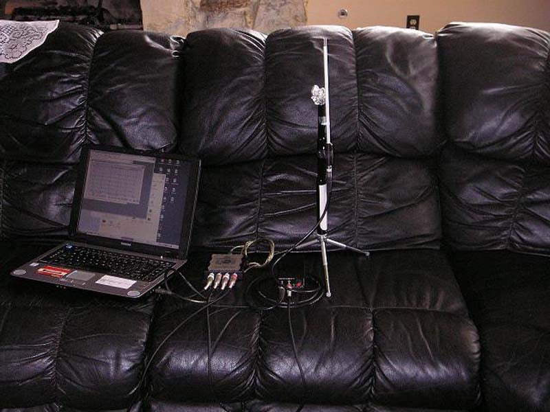
subwoofer placement, and room acoustical properties. I used the Rives Bass and
Room Evaluation (BARE) analyzer with the omni-directional microphone placed at
the primary listening position, with the SC-1250 amplifier set to the Reference
Level EQ setting for all recorded measurements. All of the surround sound
speakers were deactivated so they wouldn’t interfere with the subwoofer
measurements. The Rives BARE system is fairly basic, giving me only
two frequency response graphs to work with (5-50Hz and 5-500Hz) I decided to
measure the response using both for a more accurate representation of how the
subwoofers measured.
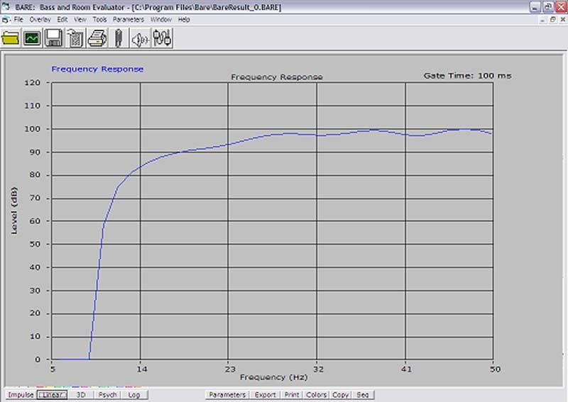
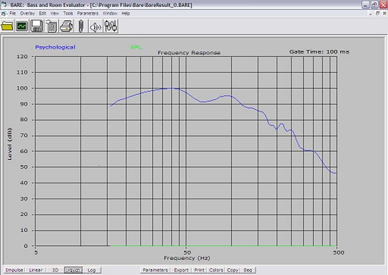
The first measurement taken 5-50 Hz, to my surprise measured fairly flat from about 18Hz-50Hz. As you can see the response dropped off rapidly at about 16Hz. Considering the SC-IW has an advertised low frequency cut off of about 22Hz I would say these subwoofers actually exceeded the manufacturers low frequency specification in my room. The second measurement of 5-500Hz shows a very similar response from 5-50Hz, a 10dB dip at 55Hz and then a gradual roll off at 60Hz. This is exactly what I expected as the receiver’s internal x-over is set for 60Hz. The dip at 55Hz is a characteristic of the room, as this room has absolutely no acoustical treatment in it at this time. Considering the less than perfect room conditions and the subwoofer placement issues I had to deal with, I was quite surprised to see the relatively good frequency response measurements.
SC-IW Listening Tests
Listening Evaluation Movies
 I decided to
use the older not particularly great movie DVD: Dare
Devil (Directors Cut). I selected this movie because it has a terrific DTS soundtrack,
excellent music score and phenomenal low frequency. Beginning with chapter four
“The Accident, Matt arrives just in time to see his dad strong arm a gambler
for a loan shark in the alley. Confused and dismayed Matt drop his straight “A”
report card in the puddle of water and runs away. As Matt runs away there are
several low frequency bass drum beats, the SC-IW subwoofers reproduced this
subtle low frequency effect with a very high degree of accuracy. This is a very
important part of the music/effects passage that leads up to the chaotic
accident and is designed to prepare the viewer for an important event and sets
the tone of desperation for the movie. I have heard this series of low
frequency effects many times with several different subwoofers. A very good
subwoofer should reproduce the deep pounding of the drum with authority and the
bass beats as they occur should decay quickly. I listened to this part of the
chapter over and over again; the SC-IW consistently reproduced the low
frequency effect and music score leading up to the accident perfectly. The
consistent beats of the drum sounded tight and the notes decayed as they should
with no over hang, lag or unwanted rumble. I was fairy surprised to hear such
accuracy, considering the subwoofer is installed in the wall. When I first
installed the woofers, I had the assumption that I would hear some boom,
exaggeration and overhang because this is what I have experienced with in-wall
low frequency transducers in the past.
I decided to
use the older not particularly great movie DVD: Dare
Devil (Directors Cut). I selected this movie because it has a terrific DTS soundtrack,
excellent music score and phenomenal low frequency. Beginning with chapter four
“The Accident, Matt arrives just in time to see his dad strong arm a gambler
for a loan shark in the alley. Confused and dismayed Matt drop his straight “A”
report card in the puddle of water and runs away. As Matt runs away there are
several low frequency bass drum beats, the SC-IW subwoofers reproduced this
subtle low frequency effect with a very high degree of accuracy. This is a very
important part of the music/effects passage that leads up to the chaotic
accident and is designed to prepare the viewer for an important event and sets
the tone of desperation for the movie. I have heard this series of low
frequency effects many times with several different subwoofers. A very good
subwoofer should reproduce the deep pounding of the drum with authority and the
bass beats as they occur should decay quickly. I listened to this part of the
chapter over and over again; the SC-IW consistently reproduced the low
frequency effect and music score leading up to the accident perfectly. The
consistent beats of the drum sounded tight and the notes decayed as they should
with no over hang, lag or unwanted rumble. I was fairy surprised to hear such
accuracy, considering the subwoofer is installed in the wall. When I first
installed the woofers, I had the assumption that I would hear some boom,
exaggeration and overhang because this is what I have experienced with in-wall
low frequency transducers in the past.
Pleasantly surprised, I progressed through the chapter until Matt reaches the accident scene. As he is running though the work yard, the LFE soundtrack really comes alive and so did the Velodyne SC-IW subwoofers. As the fork lift hits the drum filled with radio active material, my whole room began to shake with the constant rumble of low frequency bass as Matt’s life is changed forever. In the next sequence of events, the scene and the soundtrack change abruptly into what I can only describe as a hallucinogenic mind trip. Suddenly, Matt awakes in the hospital bed gasping for air unsure of his circumstances. As this occurs and as he rapidly rises out of the hospital bed, there is wave after wave of subsonic chest pounding bass, a recreation of his newly acquired super human hearing. Every little sound is amplified to bone crushing level. This short but powerful part of the soundtrack can kill all but the mightiest subwoofers when played at reference levels. Many times I have heard the awful “Clack” sound as the woofer bottoms out trying to reproduce this wave of bass. It takes a very capable subwoofer to effectively reproduce the violent howitzer cannon like bass effect and the SC-IW didn’t disappoint. As I sat listening, my body feeling the tremendous pounds of the LFE, the first thought that came into my mind was that I was listening to a very good stand alone box style subwoofer. Accuracy, pitch, and definition as reproduced by the Velodyne in-wall subwoofers were exactly what you would expect from a good mid sized subwoofer that is not installed in a wall. Yes, you read it correctly! I turned the volume up on my Yamaha RX-V4600 receiver and the SC-IW subwoofers blasted out the loud low frequency bass along with the sounds of the city and hospital contained in the soundtrack. The two Velodyne subwoofers filled my room with tremendous amounts of clean bass.
However, when I pushed these subwoofers to levels that you would only hear in military combat, they started to sound a little aggressive and less composed. This is to be expected given the size of the woofer contained in the SC-IW .My recommendation would be to install two SC-IW subwoofers in larger rooms. The rhythm, accuracy, definition and SPL slam that two subwoofers produced in my medium sized room at higher than modest listening levels was on par with many free standing 10-12-inch box subwoofers and in some instances the SC-IW subwoofers exceeded the performance of their boxy brethren. Immediately after the somewhat lengthy low frequency medley concluded, I hesitantly placed my hand on the top cover of Velodyne SC-1250 amplifier. Surprisingly the amplifier was just barley warm to the touch. This is important because it ensures the SC-1250 amplifier shouldn’t have any trouble installed in a closed equipment rack with adequate ventilation and proper component spacing.
Listening Evaluation Music
I have often
wondered why some of the most beautiful voices and talented music artists are
not used for music evaluation. As self proclaimed audiophiles and videophiles,
we seem to have a strong bias about what type of music should and shouldn’t be
used for equipment evaluation and demonstrations. Yet we continually pass over
some of the most talented performers in the music industry to maintain our
sometimes bloated audiophile credentials. I must admit that I am just as guilty,
using only what I believe to be reference material and thinking it must meet a
strict standard for my readers. Today’s modern country music performers are
just as popular and in some cases more talented than yesteryear’s rock stars.
The yodelling and twang that permeated the air waves in the 50’s, 60’s and 70’s
is now pretty much a thing of the past. Modern big billboard county music
singers and bands debunk the typical bumpkin stereo type tag that is often
placed on them. Brooks & Dunn, a band that has been filling sold out arenas
for about the last two decades, is what I would characterize as two fun loving
country guys surrounded by a rock band. Their music can be fun and fast paced
or slow and thought provoking.
 I began the
listening evaluation with CD Brooks & Dunn, The Greatest Hits
Collection II This CD is wonderfully recorded to audiophile reference
levels and the music contained in the CD is just awesome. Track 3, “Ain’t Nothing ‘Bout You”, starts out
rather quickly with an electric guitar, fast mid bass drum beats followed by an
electric steel guitar with bass guitar mixed in. Breaking down the first part
of the song from a technical stand point, the subwoofer in the system must be
able to reproduce two different bass instruments at different frequencies at
the same time. The drum and the bass guitar
in the first part of the passage are recorded at roughly the same reference
level. High performance subwoofers should be capable of reproducing the notes
of both instruments so that one doesn’t dominate over the other. In other words
you should be able to hear the drum and bass guitar clearly producing the notes
at the same time. I have listened to this opening passage with subwoofers that
were not capable of reproducing the instruments accurately.
I began the
listening evaluation with CD Brooks & Dunn, The Greatest Hits
Collection II This CD is wonderfully recorded to audiophile reference
levels and the music contained in the CD is just awesome. Track 3, “Ain’t Nothing ‘Bout You”, starts out
rather quickly with an electric guitar, fast mid bass drum beats followed by an
electric steel guitar with bass guitar mixed in. Breaking down the first part
of the song from a technical stand point, the subwoofer in the system must be
able to reproduce two different bass instruments at different frequencies at
the same time. The drum and the bass guitar
in the first part of the passage are recorded at roughly the same reference
level. High performance subwoofers should be capable of reproducing the notes
of both instruments so that one doesn’t dominate over the other. In other words
you should be able to hear the drum and bass guitar clearly producing the notes
at the same time. I have listened to this opening passage with subwoofers that
were not capable of reproducing the instruments accurately.
Editorial Note on Speed and Accuracy of Subwoofers
What’s heard is a blurring of the drum and the bass guitar with the drum dominating and the bass guitar muted. This occurs because the subwoofer can’t maintain a high degree of accuracy. This, in technically not accurate audiophile speak can also be referred to as the speed of the subwoofer. Throughout my years as an installer, I have often found that high end sealed subwoofer designs, when designed correctly, are very accurate. This is not a blanket statement about subwoofer design in general because advanced engineering and software have improved other subwoofer designs significantly. It may just be my own personal bias but I never grew attached to subwoofer designs that have the driver firing down toward the floor. The subwoofers that have drivers firing toward the floor seemed to do a fine job filing the room with generous amounts of tactile response, but in my opinion they always sounded sloppy and in-accurate for highly technical music passages. The SC-IW subwoofer is a sealed design, but the driver when installed in the wall either fires up or down. Try as I might during the installation of the subwoofers I couldn’t set aside my bias that a good music subwoofer needs to mechanically point out into the room.
As I started listening to the music, I quickly realized that the SC-IW subwoofer shouldn’t be lumped into the downward firing subwoofers that I have heard in the past. Proceeding through the evaluation, the drum and the bass guitar notes were distinct, nicely separated, and heard with relative ease when being reproduced by the in-wall subwoofers. The Velodyne subwoofers integrated beautifully with the rest of the speakers I had in my system. Bass transitions were very smooth and there were no notable gap’s in the lower frequency response. I did however detect a very slight amount of exaggerated over emphasized bass from the bass guitar as the song progressed. For comparison, I have one of the most accurate subwoofers on the planet, the mighty HGS-15X, also manufactured by Velodyne. Don’t let the age fool you, having had many high end subwoofers in my system, I can tell you the HGS-15X is the George Foreman of subwoofers. Continuing the comparison evaluation with the HGS-15X, I did hear some performance differences, most notably the way the instruments interacted with each other. The differences were not night and day between the two different subwoofers but they were there. The HGX-15X produced the bass notes from the instruments with the same degree of authority but decay time between the notes happened much quicker with no overhang or exaggeration. Overall the bass presentation with the HGS-15X was much smoother and more refined. I believe the interaction and coupling between the SC-IW’s enclosure and the wall surface to be the contributing factor. I am not entirely sure it’s fair to compare one of the best sealed subwoofers ever built to an in-wall subwoofer. However, if you are a very picky audiophile primarily listening to complex music passages perhaps you should consider a high end free standing subwoofer. The two SC-IW in-wall subwoofers did a very good job in my room with music; I would say the performance level of the subwoofers rivalled very good 10-inch sealed stand alone subwoofers. If your music tastes are geared more towards Country, Rock, Jazz, R&B, Hip Hop or Rap you will really like what you hear from the Velodyne in-wall subwoofers.
SC-IW Conclusion
As designers and their design philosophies continue the path of less is more, engineering audio products that conform to the minimalist profile without performance sacrifice can be virtually impossible. No where is this truer than with subwoofers. Here is the concept: Take a large freestanding box subwoofer, shrink it down to fit in a 2x4 wall and still maintain high performance levels, Yeah I wouldn’t have believed it either. Yet, this is exactly what Velodyne has accomplished. The Velodyne SC-IW in-wall subwoofer rivals the performance of many very good 10-12-inch freestanding box subwoofers. Once installed, the only tell tale sign that you have a subwoofer in your room is the small unobtrusive grill. If your plan is to build a high end home theater system with little compromise in performance and minimalist design cues, this is your subwoofer. The SC-IW installation process is fairly straight forward, but if you have an older home it can present some interesting challenges. Careful planning, placement, and caution must be adhered to during the installation process.
Overall, the SC-IW subwoofers performed well beyond my expectations and erased any preconceived notion that I had about in-wall subwoofers. The SC-1250 amplifier is a sophisticated power monster that provided flexible connectivity and very good room equalization software. The SC-IW is not without faults as outlined in the music evaluation part of the review, but this is rather trivial considering this is an in-wall subwoofer system. In my modest sized room, two of the SC-IW subwoofers in conjunction with the SC-1250 amplifier achieved incredible performance levels with all but the most sophisticated soundtracks. Needless to say the Velodyne SC-IW is the best in-wall subwoofer system I have heard or installed to date. I highly recommend the SC-IW subwoofer and SC-1250 amplifier to home owners, custom installers, and designers that wish to maintain the minimalist design trend without performance sacrifice. –Bravo Velodyne!
345 Digital Drive
Morgan Hill, CA 95037
Tel: (408)
465-2800
Fax: (408) 779-9227
www.velodyne.com
Company Overview
Velodyne Acoustics, Inc., founded in 1983, is universally recognized as the leading manufacturer of high-performance, low distortion powered subwoofers at all price levels. Headquartered in Silicon Valley, California, the company's technically innovative audio products are available through a select group of authorized dealers, custom installers, and distributors worldwide.
The Score Card
The scoring below is based on each piece of equipment doing the duty it is designed for. The numbers are weighed heavily with respect to the individual cost of each unit, thus giving a rating roughly equal to:
Performance × Price Factor/Value = Rating
Audioholics.com note: The ratings indicated below are based on subjective listening and objective testing of the product in question. The rating scale is based on performance/value ratio. If you notice better performing products in future reviews that have lower numbers in certain areas, be aware that the value factor is most likely the culprit. Other Audioholics reviewers may rate products solely based on performance, and each reviewer has his/her own system for ratings.
Audioholics Rating Scale
 — Excellent
- — Very Good
- — Good
- — Fair
- — Poor
| Metric | Rating |
|---|---|
| Bass Extension | |
| Bass Accuracy | |
| Build Quality | |
| Ergonomics & Usability | |
| Features | |
| Performance | |
| Value |