
Velodyne DD-18 Subwoofer System Review
- Product Name: Velodyne DD-18 Subwoofer
- Manufacturer: Velodyne
- Performance Rating:

- Value Rating:
- Review Date: January 18, 2007 19:00
- MSRP: $ 4999
|
Sensitivity (2.83 V/1m): |
89.5 dB spl |
| Amp. Power: | 1250 Watt RMS, Class D digital-switching power amp |
| Rated Impedance: | 4 Ohms |
| LF Frequency Response (+/- 3, -6, -10 dB): | 16 Hz (-3 dB); 14 Hz (-6 dB);13 Hz (-10 dB) |
| Bass Principle: | Acoustic Suspension |
| Shipping Weight: | 54.0 kg (120 Lbs) |
| Cabinet Dimensions (W x H x D): |
539.8 mm x 584.0 mm x 489 mm
(21.25 ” x 23.0 ” x 19.25 ”) |
| Active Processors |
Crossover: active lowpass
filter, variable,15 - 199 Hz with variable slope, 6 – 48 dB /Octave in 6 dB increments; Subsonic filter: 15 – 35 Hz, with variable slope, 6 – 48 dB /Octave in 6 dB increments; Phase: Variable from 0 – 180 degrees in 15 degree increments; Polarity: adjustable (+/ -) 8-band Parametric EQ: Variable Q (.1 to .9 octave), variable gain\attenuation level (+6 to -12 dB), and variable frequency (20, 25, 32, 32, 40, 50, 63, 80, 100 Hz, with an effective domain of 15 – 120 Hz) PEQ can also operate in graphic EQ mode |
| Connection: |
Inputs: LFE (Mono) XLR &
RCA; Line Level (L & R) RCA; Microphone: XLR; Speaker Level (L & R): 5-way gold-plated 5-way binding post Outputs: Thru (L & R) Line Level: RCA; Output (L & R) Line Level RCA; EQ Out (L & R): RCA; Video Out: |
| Recommended Placing: | Position determined on test at setup time. |
Pros
- Extremely Low Distortion
- Auto PEQ
- Selectable Preset Listening Modes, Including EQ Defeat
- Includes Calibrated Mic & Accessories
- Advanced Digital Control System
- Advanced Driver Design
- Useful Manual Included
- Remote Control
- Daisy-chain With Multiple DD Series Subs
Cons
- Mic clasps don’t fit standard mic stand mount
- HP filter not adjustable
Company History
Velodyne is a company that has specialized in the production of subwoofer
systems (servo-controlled or  otherwise),right from its inception in 1983. In
1984 Velodyne patented and subsequently put into production the world’s first
high-gain, servo-controlled subwoofer -the now-classic ULD-18.
otherwise),right from its inception in 1983. In
1984 Velodyne patented and subsequently put into production the world’s first
high-gain, servo-controlled subwoofer -the now-classic ULD-18.
Since the debut of
that first product twenty-some-odd years ago this Morgan Hill, California-based
company has gone on to produce dozens of other highly successful products, at
the same time racking up several additional
patents along the way.
Fig. 1: Home of the Heavyweights
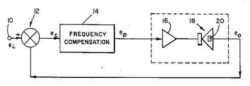
Fig 2: Illustration from U.S. Patent # 4, 727,584, “Loudspeaker With Motional Feedback”
In the DD-18 we
find the successful embodiment of such patented, innovative technology, 2+
decades of design & build know-how and some exceptionally useful extra
features.
First Impressions
The DD-18 sports what is just about the smallest cabinet I’ve ever seen an 18” driver bolted into.
Still, it weighs a little over 120 lbs (54.4 kgs) and has a
finish that you won’t want to see scratched up. (I’d describe it as “French
polish”). Add to that a driver with an effective surface area a little over 180
sq. in (read: target easily hit by unforgiving objects) and its clear care
& forethought are the order of the day when unpacking.
I found it expedient to open the top, remove the small
carton containing the measurement mic, cables, etc, then turn the shipping
carton upside down, finally lifting it off the sub. It was quite the moment
seeing the DD-18 unveiled for the first time!
The supplied review model featured a cherry finish and black
grille cover. The quality of the natural wood finish is about the best I’ve
seen thus far in a sub destined for home use (more typical of what you find in
high-end furniture) and will likely push the SAF approval value in the right
direction. As you may have already
guessed, the quality of both fit & finish are exactly what you’d expect
from a sub in this price class. A real advantage, as my experience has been
that with subs featuring such top-caliber aesthetics as the DD-18 it’s a lot
easier to find a permanent place to park the unit in your listening space.
In the real world, placement is a compromise result that
arises from the tug-of-war between acoustical performance (where in this room
will this thing perform at its best?), aesthetics (where does it look best or
least offend spouse or significant other(s) visual sensitivities?), and logistics
(waddya mean I can’t tear out grandma’s beloved antique potbellied stove!? –
it’s the best place for the new sub!).
Clearly, in a situation like this, the nicer looking the unit the less likely the need to hide, resulting in a bit more flexibility in picking a spot for the sub. I didn’t find a need to hide this sub away anywhere – it’s that nice looking.
 |
 |
 |
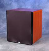
| Cherry |
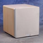
Maple |
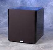
Black |
(6 additional special order finishes are available)
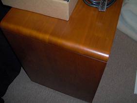
Figure 3: Cherry finish Close Up
Velodyne DD-18 Inside Look
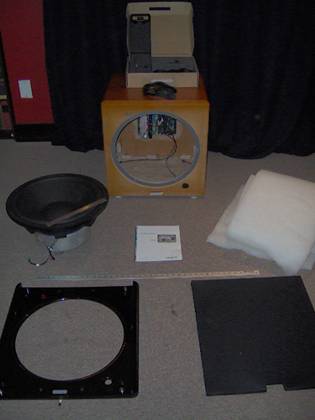
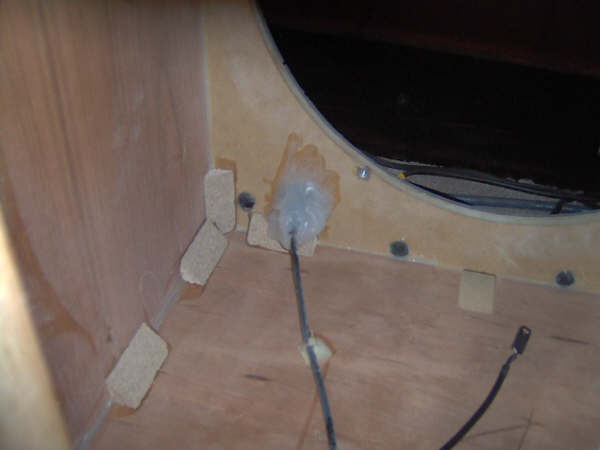
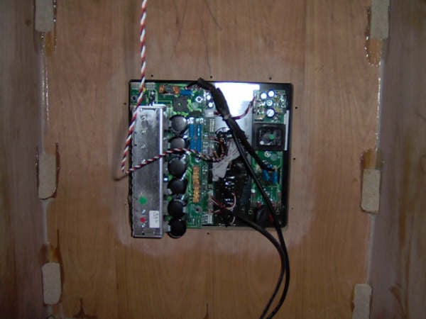
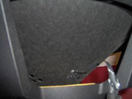
Figures 4a – c: Inside the DD-18 (Left): System disassembled, meter stick & 12” ruler included for scale; Middle: Looking forward from back of cabinet toward inside of faceplate. Note XLR jack sealed in silicon to eliminate wind noise. (Any hardware found in the amplifier - or anywhere else in the cabinet - that could provide a path for air leakage was sealed). Light gray band seen in driver aperture is the gasket. Dark lead seen at lower-right of the photograph supplies faceplate indicator light with current. Right: looking back at cabinet back panel and system amplifier, Note use of glue blocks throughout.
Removing the grill cover, black gloss-finish fascia and driver revealed a moderately damped, well sealed cabinet built up of 1” (2.54 cm) panels. Glue blocks were used throughout. No cross bracing of any kind was used in construction of the cabinet. Driver and fascia held in place using Allan-bolt/t-nut mounting hardware. Both driver & amplifier openings are gasketed. The system rests upon 4 ¼-20 threaded aluminum feet with rubber inserts. They work very well in making sure the unit stays put.
The driver used in the DD-18 is certainly an heroic looking device! Features include a Kevlar-reinforced cone with a 15.2” (38.6 cm) effective radiating diameter, variable-thickness EPDM surround, 1.25” (3.18 cm) (peak-to-peak linear excursion (1.75” (4.45 cm)(on transients), tandem, 3” (7.62 cm) wide, 6” (15.24 cm) long, push-pull voice coil, wound on a woven glass/polyamide resin former, a 24lb (10.89 kgs) magnet structure and a die cast aluminum basket.
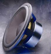
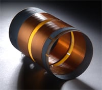
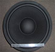
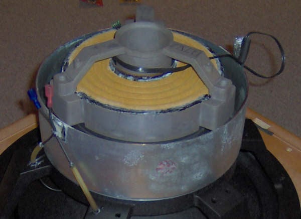
Figures 5a –c Bottom right: DD-18 Driver with 1’ ruler included for scale; Top left & right: driver and voice coil. Bottom left: close up of motor assembly. At left in image: power leads encased in surgical tubing. Image center: bottom of drivers two linen spiders showing. At right of image: Accelerometer leads. Velodyne doesn’t attempt to make their drivers pretty for press photo shots. You won’t find any chrome or gold finish, just a raw, high performance driver. But then again, beauty is in the eye of the beholder.
Figures 6a,b: Left: DD-18
Accelerometer (left end attached to driver). Right: Accelerometer & lead
seen at right. Note holes in the bottom, left-hand side of cone.
Yet another interesting feature of the DD-18’s driver are
the clusters of small holes seen at the bottom of the cone in Figure 6b. Purpose? Velodyne’s design intent
can be found in the Description of the
Preferred Embodiment section of US Patent #4,727,584 “Loudspeaker with
Motional Feedback”:
“The function of the hole clusters 38 is to control the speed of waves propagating radially outward of the cone, so as to provide that the speed varies to some extent with the radial angle. That is, the propagation speed in the sectors containing a cluster of holes will be different from an adjoining sector not containing such a cluster. Sonic waves resonate at a slightly higher frequency between the hole clusters than through the clusters. The consequence of such an arrangement is that a somewhat “jumbled” pattern of sound waves is created, which apparently combine in a fashion to prevent marked resonance effects leading to instability.”
The Amp & Digital Drive: The Virtuous Cycle
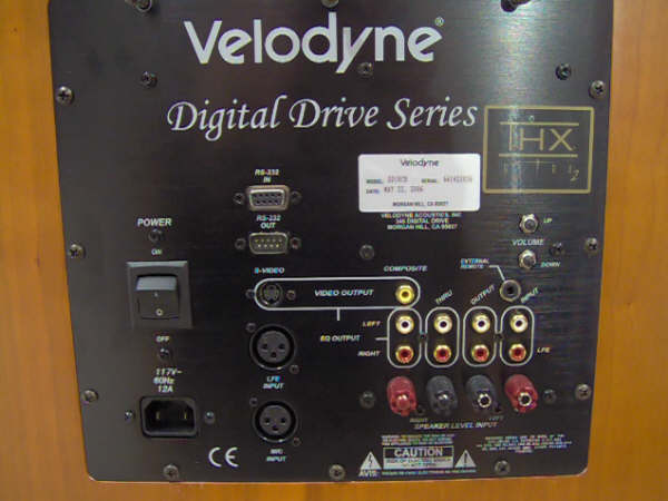
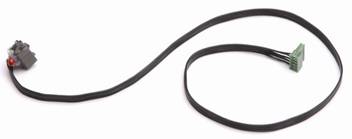
Figures 7a,b: (Left) DD-18
Amp. Note array of jacks at left running top to bottom, sealed to prevent air leakage. (Right) DD-18
control panel, recessed & gasketed, bolted into back of cabinet. Provides
data, audio & video interconnects along with On/Off switch and volume
control.
Digital Drive is an impressively comprehensive subwoofer control system. It encompasses digital implementations of all crossover, filter, phase, contour functions as well high-gain servo control (featuring accelerometer A-D sample rates up to 15.8k) and all linked into an extremely efficient Class D power amp.
Interaction with the system is via a remote (supplied with batteries!) and user-supplied video display capable of handling either S-video or composite video signals.
System feature highlights include:
- On Screen Display presenting a total systems control interface
- 8 – Band parametric EQ, with level, frequency & Q control parameters, of course.
- Low-pass crossover filter
- Subsonic filter
- Phase control
- Polarity control
- 6 Listening-mode Presets (4 factory set, 1 user customizable and EQ Defeat)
- Contour EQ (Freq. & Level adjustable) for each preset
- Master system volume control & individual Presets volume control
- Servo loop gain control (1: lowest loop gain – 8: maximum loop gain)
- Night mode option
- RS-232 Input
- System Firmware is user-updateable
- System capable of managing daisy-chained subs.
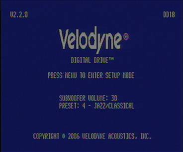
Figure 8: Introductory Screen.
Power up the DD-18 and the introductory screen is what your OSD greets you with. It presents basic operational information such as Firmware version, Model ID, sub volume and whichever default preset has been selected.

Punch “Menu” then “12345” on the remote and you’re taken to the System Response\PEQ Screen (Figure 9). Here, the system indicates the volume is at 30, manual mode is in effect and the response is flat lining as the supplied setup mic was not connected to the system when the screen capture was done.
Setting equalization can be fully
automatic, fully manual or a combination of the two, letting, the DD-18 run the
equalization set up automatically, then manually tweaking the results. The
system monitors the process and its effects on the resulting dB spl curves via
the supplied mic. Being able to watch changes in DD 18’s amplitude response due
to changes made at the PEQ is as useful as it is efficient.
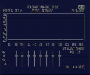
Figure 9: System Response\PEQ Screen
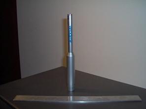
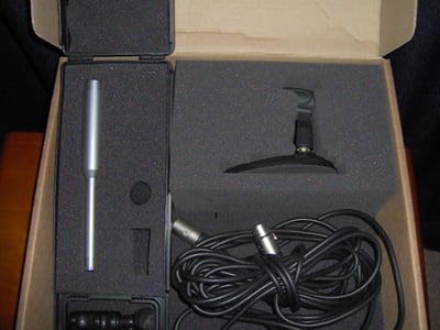
Figures 10a, b: Mic w\ 1’ ruler for scale, Mic kit with accessories
Figures 10a & b show the included mic along with various included accessories, such as the tabletop mic stand, mic clip for stand mount, 20’ XLR to XLR mic cable, windscreen, and carrying case. Also included but not shown are a 25’ video cable and 25’ audio cable.
Velodyne DD-18 Set-up
The calibrated mic\real-time response plot display is a combination superbly suited to getting the DD-18 properly set up. In addition to the benefits already mentioned, the real-time display can make quick work of locating suitable positions for the sub: simply place the sub at your main listening position, set the DD-18 to generating its test tone sweeps (Sine wave, 15 Hz to 200 Hz, with tracking bandpass filter) and walk around the room with the mic in hand and watch the effect your position has on the response displayed. No more crawling for bass! Eventually a few spots within your listening space suitable for your sub (acoustically speaking) will emerge.
Once these are identified, move the sub to whichever of the spots it is practical to do so and run the EQ process. To make it easy to compare before/after PEQ for each spot I fed the video stream to a PC and put together a collection of screen captures. Snapping pictures with a digital camera and looking over the results afterward would work just as well.
Running the EQ
process is pretty easy to do. In general form, here are the steps:
1. Make certain both sub and AVR are off.
2. Connect the mic to the DD-18 (jacks are provided on both front & back panels).
3. Connect the sub’s EQ Out to an appropriate input on your AVR.
4. Turn on AVR & Sub, turn down gain on each to mute output
5. Set sweeps running and increase gain on AVR to a
comfortable level, then increase subs
gain until the two response plots appear roughly equivalent in terms of
amplitude magnitude. Set crossovers, slopes, phase and polarity,
primarily to get
the crossover point with the mains right, then go to PEQ (step 6).Proceeding in this
way allows for a minimum of PEQ required to tune the sub.
6. Set Equalization mode to Automatic and let the DD-18 calculate a solution. It’s fascinating to watch the display as the system homes in on a solution.
7. Once the auto process has run to completion, manually tweak the PEQ settings (if so desired) and save. Note: When tweaking system settings (Fig. 11), use the Test key to jump back and forth to the system response screen and see the results of the latest efforts. When all is maximally tweaked, save.
If your processor/receiver is running bass management, defeating the DD 18s internal crossover is a common practice. This can be done when you’re in the System Settings screen by setting the low pass crossover slope & frequency to “OFF”. (See Figure 11).
The manual provided with the DD-18 (available online as well) provides, of course, far more detailed instructions and comes highly recommended. I suggest reading through it a few times before running the process.
The third and final screen in the series presented by the DD-18 is the Presets screen, seen in Figure 11.
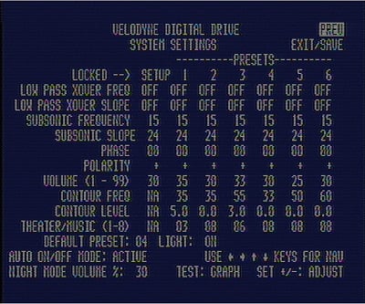
Figure 11: DD-18 Presets Screen
The DD-18 comes from the factory with its 6 presets preset. (One of the six functions as an EQ defeat)
On the remote they’re labeled:
1. Action/Adventure
2. Movies
3. Pop/Rock
4. Jazz/Classical
5. Custom (yours to tweak as you see fit to do)
6. EQ Defeat (especially useful for before/after comparisons
with Preset 5)
Referring to Figure 11, from the top down the function/parameter fields are:
- Lowpass Crossover Frequency: adjust the upper limits of the subs response
in terms of frequency (15 Hz to 199 Hz, increments of 1 Hz)
- Lowpass Crossover Slope: adjust the upper limits of the sub’s response
in terms of slope (6 dB to 48 dB/Octave in 6 dB/Octave increments).
- Subsonic Filter Frequency: Set the sub’s LF limit in terms of frequency (15 Hz – 35Hz, 1 Hz increments)
- Subsonic Filter Slope: Set the sub’s LF limit in terms of filter slope (6 dB – 48 dB/Octave, 6 dB increments)
- Phase: Set sub’s output signal phase (0° to 180°, 15° increments)
- Polarity: Set subs polarity (toggle between “+” and “-“, equivalent to a 180° phase reversal
- Volume: Set individual preset volume (gain) separate from that of system master gain control.
- Contour Frequency: Sets contour boost/cut frequency of Contour EQ
- Contour Level: Amount of boost/cut at contour frequency of Contour EQ
- Theater/Music: Set the amount of distortion-limiting servo gain; 1 (Theater, min. servo gain)
8 (Music, max servo gain, minimum distortion).
- Default Preset: Select the sub’s default preset; the preset the sub automatically runs at startup.
- Auto On/Off Mode: On at signal sense, off 15 minutes after the last detected signal.
(L & R In sum to mono, in effect, increasing sensitivity to the incoming signal by the auto on/off process, making it more effective at detecting low-level signals).
- Night Mode Volume: Preset max. gain level.
- Light: Sets the logo light on or off. Default is on.
So how well did the PEQ work?
Pretty well, actually. Figures 12, 13, and 14 tell the story.
Figure12 is the pre-AutoPEQ picture, Figure 13, post-AutoPEQ and Figure 14, post-AutoPEQ followed
by a modest amount of manual tweaking. Subjectively speaking, the audible difference between the system response as seen in Figure 12 & 14 was truly substantial; best described as the lowest few octaves of the system pulled into focus, delivering an increase in precision and clarity that would have to be heard to be believed. Excellent!
There are a couple things that should be kept mind when viewing the figures. First, the plots generated by the Velodyne display are 1/3rd Octave smoothed. Second, the amplitude response generated is for the main listening position only; move away from that position and the response will change both audibly & measureably.
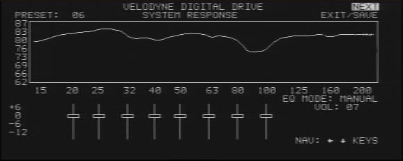
Figure 12: System response, pre- AutoPEQ, as measured at the main listening position 9’ (2.7m) directly in front of sub.
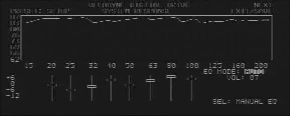
Figure 13: System response, post- Auto PEQ, as measured at the main listening position 9’ (2.7m) directly in front of sub.
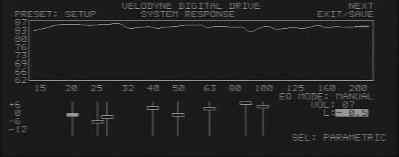
Figure 14: System response, post- Auto PEQ, with additional manual tweaking, as measured at the main listening position 9’ (2.7m) directly in front of sub.
Velodyne DD-18 Measurements and Analysis
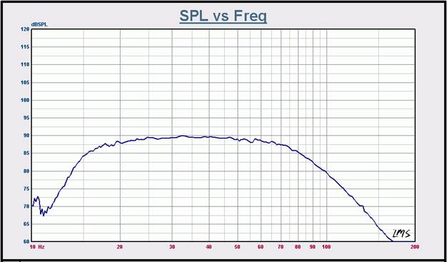
Graph 1: System amplitude response, 1m, On-axis @ 2.828 Vac , Preset 4 Engaged. Measurement environment: Outdoors, nearest reflecting surface: 30m (~100’) No smoothing applied.
In Graph 1 we see the DD-18, measured outdoors, pole-mounted, driver firing upwards, approximately 30m (~100’) above the ground. The system’s measured amplitude response goes far in explaining the sub’s exceptional subjective characteristics. The smooth mid-band performance, artifact-free low & high frequency roll off, are all factors contributing to the systems 5-star performance. (The hashy appearance of the response plot in ~<12 Hz was due to a low flying airplane that happened by while the sweep was underway and should be ignored).
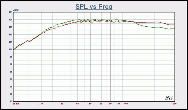
Graph 2: Max dB spl curves, 2m, on-axis, scaled to 1m. Green curve: Servo @ 1, Red Curve: Servo @ 8. Measurement environment: Anechoic.
Graph 2 shows the DD-18’s max. dB spl response plots, with two curves provided to present the systems response with Servo gain at 8 and at 1.Increased distortion components add in to the mix increasing dB spl output slightly at Servo setting 1. The degree to which increased distortion will increase the overall amplitude magnitude is frequency dependent. Note also the upward shift of the LF knee when compared to that seen in Graph 1. This results from the processors functioning correctly and keeping the driver’s excursion within software-defined, safe limits.
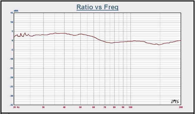
Graph 2b: Normalized THD&N curves; Servo settings 8 & 1
I also ran 2 quick THD&N sweeps, one at Servo setting 1 and again at 8, both at the same drive level used in generating the curves seen in Graph 2. Dividing one curve by the other for easy comparison, the results are seen in Graph 2b. Not unexpectedly, an increase of a few dB below about 65 Hz is seen in the THD&N levels at Servo setting 1 when compared with Servo setting 8. (Had both THD&N curves been identical, normalizing one to the other would have produced a flat line spanning the graph at 0 dB).
Graphs 3 – 8 are a walk through the various digital processing features built in to the DD-18; tested/measured not only to see if they work (don’t laugh – I’ve bumped into subs where some of the processors didn’t function correctly) but how and how well they work.
The subsonic filter (Graphs 3 & 4), Contour EQ (Graph 5)(acts as an extra, limited-function EQ), low pass crossover (Graphs 6 & 7), and PEQ in combination with the supplied mic (Graph 8, along with Figures, 12, 13, and 14) are all essential features that help the end user integrate the sub with their existing system while at the same time maximizing the performance of the sub within that system, further helping to maximize the performance of the entire system. With the comprehensive array of processor/control features and the Velodyne everything-is-important design approach where it comes to the cabinet, driver, servos, & power amp, you have in one neat package all the ingredients for a world-class sub. Just get it. You can always turn it down later if it’s too loud.
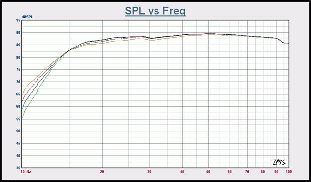
Graph 3: Subsonic filter slope, 6, 12, 18, and 24 dB/Octave. Filter frequency: 15 Hz. Measurement environment: Nearfield, scaled to 1m.
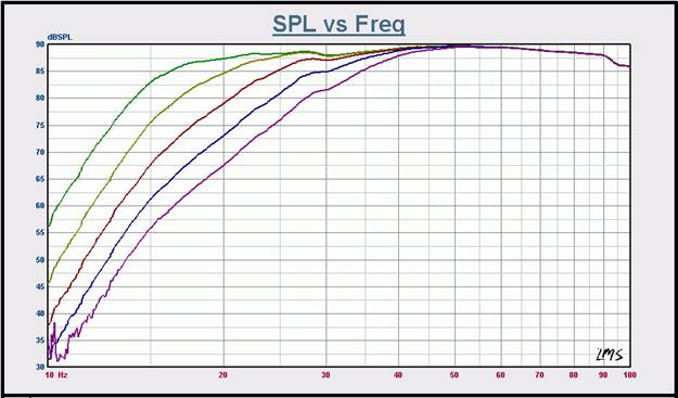
Graph 4: Subsonic filter frequency, 15 to 35 Hz in 5 Hz increments. Slope set to 24 dB/Octave Measurement environment: Nearfield, scaled to 1m.
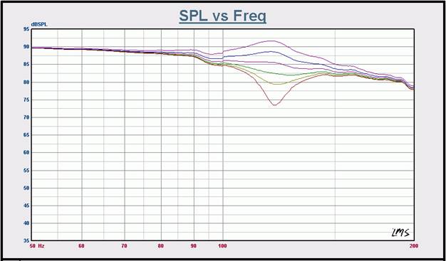
Graph 5: Contour EQ: +6 dB to -12 dB in 3 dB increments. Contour frequency: 120 Hz
Velodyne DD-18 Measurements Cont.
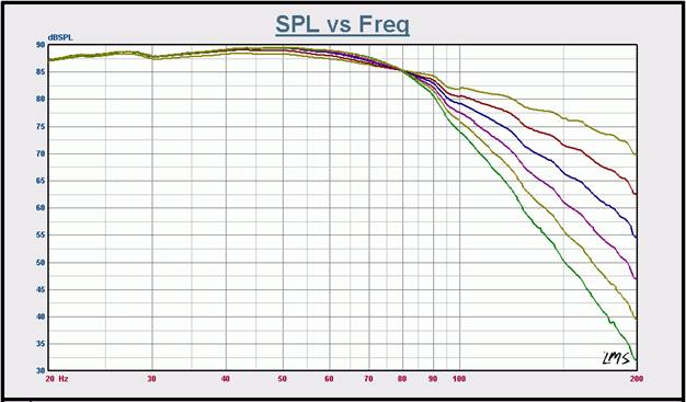
Graph 6: LP Crossover: Slopes from 6 to 36 dB in 6 dB increments. Crossover frequency: 80 Hz. Measurement environment: Nearfield, scaled to 1m, On-axis @ 2.828 Vac.
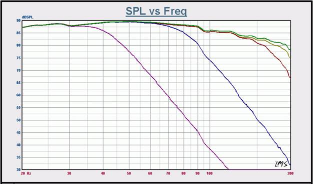
Graph 7: LP
Crossover Frequencies: Off, 40, 80, 160 & 199 Hz. Slope: 36 dB/Octave
Measurement environment: Nearfield, scaled to 1m, On-axis @ 2.828 Vac.
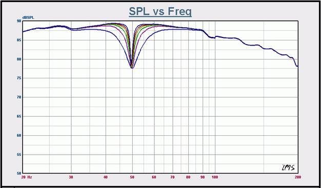
Graph 8: PEQ, Varying Q @ 50 Hz. Q = 3, 6, 9, 12, 15 & 20. Measurement environment: Nearfield, scaled to 1m, On-axis @ 2.828 Vac.
Velodyne DD-18 Listening Tests and Conclusion
The more recreational listening time I spent as a run up to
the critical listening part of this review, the more I grew to appreciate just
how truly high quality a product the DD-18 really was. It has a way of
involving you in whatever movie you’re watching or musical track you’re
listening to in an all too rare, authentic way. You’re not at the movie, you’re in
the movie. With a sub capable of plumbing the deepest depths of the
subterranean LF architecture of your favorite movie or musical selections as
well as the DD-18 does, you’ll experience an engaging, enveloping realism
that’s altogether in a class of its own - as well it should be for an MSRP of
$5k US!
Nothing like aliens trashing the neighborhood and stuff blowing up to show off a sub’s ability (or lack thereof) to deliver slam, (I mean SLAM!) in a dynamic, lively, REALISTIC way. In War of the Worlds you get plenty of alien vandalism, stuff blowing up and more, with accompanying LF passages (artillery barrages in response to aforementioned vandalism & mischief) that’ll test any system’s ability to present an authentic, robust dynamic range, low compression, low distortion and high dB spls. The DD-18 handled the job superbly never once breaking a sweat, so to speak, in dishing out the LF acoustic portion of the alien-style smash, bash & thrash party being served up on screen. In practice, I never needed to push the gain high enough to tax the DD-18. It was so capable of delivering mammoth amounts of very clean, tight, deep bass into the ~62.3 m^3 (~2200 ft^3) listening space whenever called on to do so. I’d like to mention I left the servo set at 8 (max feedback) at all times as the system was so capable of providing far more LF acoustic output than would ever be needed, that the extra bit of acoustical output gain (gotten at a cost of higher distortion) simply wasn’t necessary. (See graph 2).
Where it comes to subs I’ve always preferred running large
systems at levels the system in question would not find challenging at all, the
idea being to keep non-linear distortion at practical minimums: I’d rather have
a too-big system, running at low levels than a too-small system calling
attention to itself with its annoyingly poor performance. The DD-18 is just
such a large system, which, with its servo-controlled driver defines clean,
(i.e. low-distortion) sound. Now whether an expenditure for a sub on the order
of $5k US makes financial sense or not is a question that can only be answered
by the individual consumer. However, having experienced the DD-18 first hand, I
can tell you the quality of performance it will bring to your listening
experiences makes it well worth the
extra bit of time or effort it might take to fit this sub into your budget.
Pink Floyd’s Pulse is a two-disc set built from a series of recordings done 12 years ago at the Earl’s Court Exhibition Center in London. Sonically, it’s not bad at all for a 12 year old recording re-mixed to 5.1 format. Though the actual performance was a little uneven in spots, there are moments of sheer musical magic as well. Overall, this DVD has a way of growing on you and drawing you into the performance, much as the Dark Side of the Moon LP drew in listeners a generation ago. I listened to the DVD several times in reviewing the sub, at typical concert levels, and the Velodyne never flinched!
Of particular interest was Guy Pratt’s bass work on Comfortably Numb. Not that the bass lines were of any lesser quality elsewhere. It did seem, though, that the LF portion of many of the other tracks was rolled off a bit or compressed so much so that the Velodyne didn’t have all that much to work with, even the pyro moments sounded a bit weak in terms of dynamics. (If you’ve ever been onstage, behind or in front of a pyro cannon when it fires off, you’ll know what I mean).
Comfortably Numb,
however, didn’t sound overly compressed and the Velodyne came to life, carrying
the bass lines (and all the rest of the LF portion of the audio tracks) with
command, power, precision and a degree of musicalness largely attributable to
very low levels of distortion. I listened to a few other live music DVDs (such
as Eric Clapton’s Sessions For Robert
Johnson) and the experience was always the same. The DD-18, with its
exceptionally low distortion and the way it can finesse high output demands -
either transient or long-term in nature - all add up to a sub capable of revealing
an undiscovered dimension within the music contained in your collection of CDs
& DVDs.
Ahhh, the days when soaring, meteoric reverb tails were king! Bladerunner is an 80’s classic, perfect for the dark-film connoisseur. I settled in LA a few years after the movie came out and recall it had developed an almost cult-like following, resulting in the film remaining in the public eye for what seemed a surprisingly long time. I chose this DVD not for any exceptional sonic attributes but instead more out of simple curiosity, to see if I’d hear anything new in these old tracks. (And I do mean old: Bladerunner was one of the first movies to see a DVD release).
Put simply, I found that the DD-18 was capable of authentically
resolving bass detail in a way that is seldom encountered. I’d estimate this,
once again, owes largely to the exceedingly low levels of distortion this
particular sub is capable of. Though the movie certainly did have its
interesting ELF moments, It was the revealing of bass detail as I’d not heard
it before that really stood out. Gone were the blurred glissandi (the sliding
of pitch fluently from one note to another) and jumbled bass chords that I had
for so long accepted as symptoms of the audio production values common for
movies made in those days. Overall, I’ve never before heard any subwoofer
sporting an 18” driver capable of resolving bass detail as cleanly as the DD-18
does with aplomb. Excellent!
Mussorgsky’s Pictures at An Exhibition, transcribed for and performed on organ by Jean Guillou. (Dorian Dor – 90117) Performed on the mighty Kleuker-Steinmeyer organ of the Tonhalle, Zürich.
This CD is a real sonic treat for both the classical music fan and anyone interested in looking for an alternate to the more commonly used musical material used in assessing a sub’s subjective performance. Track 5, Promenade, and track 15, The Great Gate At Kiev feature some of the most challenging bass lines found in the literature, outside of such familiar compositions as the 1812 Overture.
The recording is well executed and with the right playback equipment its easy to hear the full extent of the bass lines as they majestically unfold across the acoustical landscape of the Zürich Tonehalle. The DD – 18 was easily able to differentiate between the deepest of pedal tones, a difficult feat for even the best.
I could play this CD’s tracks at levels sufficient to make nearby light fixtures jiggle (along with the suspended ceiling), yet the DD – 18 tracked the bass lines with a tenacious grip. It did so at such low distortion levels that it gave one a very clear view not only to the complex tonalities of the music flowing from the ranks of the Kleuker-Steinmeyer, but also, as already mentioned, the acoustics of the space within which the recording was made. If you’ve ever encountered a sub capable of this sort of LF resolution, you’ll know the result at the listeners ear is unforgettable.
Recommendations
The DD–18 is a big sub that delivers truly big sub sound. It does so with a driver packed with performance-enhancing features, as well as a sophisticated digital drive control system that works to not only keep the driver performing at its best but also ensuring the sub integrates flawlessly with the rest of your system and the acoustics of your listening space. The on-screen display system, handheld remote and calibrated mic ensure you can get your sub up & running and optimally tuned in no time at all. If you absolutely require authentic LF extension, loads of clean power, and the right mix of advanced features to deliver a level of performance that is in a class of its own - all in a beautifully finished cabinet - then the
DD–18 is the place to invest your hard earned audio dollars. ROI begins immediately and unless you’re listening space is the size of a Kansas prairie, this is likely the one and only sub you’ll need for a long, long time. Though if you desire more uniform bass distribution throughout the seated area, have the extra coin, and your abode can handle seismic tremors on a regular basis, I’d opt for two DD-18’s!
Conclusion
Velodyne has long stood out for subwoofers with exceptional performance capabilities. In the DD -18 we find a very powerful, yet sophisticated system capable of performing at quality levels that put it well above the average product. Though the demands placed on a sub by 2-channel playback and HT are different, the DD–18 handles both modes with ease. In every way that is important, the DD – 18 excels, making it a benchmark product in every category.
The Score Card
The scoring below is based on each piece of equipment doing the duty it is designed for. The numbers are weighed heavily with respect to the individual cost of each unit, thus giving a rating roughly equal to:
Performance × Price Factor/Value = Rating
Audioholics.com note: The ratings indicated below are based on subjective listening and objective testing of the product in question. The rating scale is based on performance/value ratio. If you notice better performing products in future reviews that have lower numbers in certain areas, be aware that the value factor is most likely the culprit. Other Audioholics reviewers may rate products solely based on performance, and each reviewer has his/her own system for ratings.
Audioholics Rating Scale
 — Excellent
- — Very Good
- — Good
- — Fair
- — Poor
| Metric | Rating |
|---|---|
| Bass Extension | |
| Bass Accuracy | |
| Build Quality | |
| EQ System | |
| Fit and Finish | |
| Ergonomics & Usability | |
| Features | |
| Performance | |
| Value |