
Axiom Audio EP500 Subwoofer Review
EP500 Award
- Product Name: EP500 Subwoofer
- Manufacturer: Axiom Audio
- Performance Rating:

- Value Rating:
- Review Date: October 31, 2006 08:25
- MSRP: $ 1,150
|
Enclosure: Ported bass reflex |
Anechoic Response: 20Hz – 100Hz (+/- 1.5dB) see graph |
Pros
- Admirable depth and slam
- Good output for small to medium sized rooms
- Very musical
- Balanced Inputs
Cons
- Boxy looking appearance
- Single Line Level Input
- Not magnetically shielded
- Some port chuffing at high output
- Prices have gone up substantially since publication of this review
Update: 4/20/14: Axiom has replaced these subs with smaller more expensive sealed versions. See Axiom EP500v4 and EP600v4 Subwoofer Preview for more details
Axiom EP500 Subwoofer Introduction
This is a review of the Axiom EP500 500 watt powered subwoofer featuring an aluminum 12" driver in a ported enclosure.
If
you haven't heard of Axiom Audio by now, you're probably not in touch
with the home theater scene as much as you think or you don't spend a
lot of time online researching products (perhaps a little of both).
Axiom Audio's loudspeaker design philosophies adhere to their rigid scientific measurement standards and the psychoacoustical testing protocols of the National Research Council (NRC). Axiom's founder, Ian Colquhoun, is a firm believer of the principles established by the NRC and is dedicated to adhering to these principles in all Axiom loudspeaker products.
The goal of the NRC Research, is to have manufacturers adhere to loudspeaker design practices that measure with a flat on-axis response and with an even but constantly declining (or tilting) polar response. The polar response curve is the summed and weighted average of many curves taken from either a 180 degree or 360 degree family of curves which are usually either at 10 degree or 15 degree increments through the entire measurement range.
Last fall when Axiom Audio invited us all the way to Canada to take a factory tour, I had no idea they had a couple aces in their sleeve with their new DSP driven EP500 and EP600 subwoofers. We walked away from the tour with a very positive first look into the capabilities of these new super subs. In fact, based on the performance measurements we conducted and our extensive listening tests, we awarded the EP500 our 2004 Product of the Year for the subwoofer category. Despite our very positive experiences with these subwoofers during our tour, being the Audioholics we are, we thirsted to learn how they would perform in the most critical of listening environments – our own sound labs. With that, we requested review samples of the EP600 (review forthcoming) and EP500 (my personal favorite, mostly due to its more compact size). These subs dazzled us at the Colquhoun labs, but did they do the same in our own?
Axiom EP500 Design Overview

The EP500 is unlike any other subwoofer we have encountered. Let's start with the amplifier design execution which is nothing short of brilliant.
The Amplifier
Axiom’s new digital subwoofer amp is designed from the ground up by industry veteran Tom Cumberland. Unlike most digital amplifiers, this one features an analog power supply to ensure plenty of headroom for large dynamic peaks. The EP500 gets a 500 watt version and the EP600 gets a 600 watt version
Amazingly, due to the high efficiency of this design (> 90%) I was able to touch the heat sink directly coupled to the output devices during operation without burning the skin off my finger. To get this much power out of a conventional amplifier would require nearly double the power supplied by the wall outlet which approaches the limits of most 15 amp household circuits. This is especially true when other devices are also attached to the same circuit simultaneously. The secret behind this amp is in its use of Pulse Width Modulation (PWM) technology.
Editorial Note on Class D (PWM) Amplifiers
Class D amplifiers utilize a technique called pulse width modulation which is sometimes combined with pulse frequency modulation. The input audio signal is converted to a sequence of digital pulses whose width at any time is proportional to the present amplitude of the signal. The frequency of the pulses is typically 30 or more times the highest frequency of interest of the audio signal. Unfortunately the byproduct of the output of such an amplifier contains unwanted harmonics that must be removed by a passive analog filter. The output of such amplifiers usually work best with constant impedance crossovers since they can react a bit unpredictably with highly reactive speaker loads which is why these amplifiers are best suited for subwoofer applications or specifically designed amplifier and speaker packages.The main advantages of a class D amplifier are efficiency and space savings. Because the output pulses have a fixed amplitude, the switching elements (usually MOSFETs) are switched either on or off, rather than operated in linear mode like conventional Class A/B designs. This means that very little continuous power is dissipated by the transistors except during the very short intervals of on and off states. The wasted power is low because the instantaneous power dissipated in the transistor is the product of current and voltage, both of which are almost always close to zero.
 The
back panel of the EP500 is a fully armed arsenal of connectivity
options including line level (unbalanced and balanced) inputs and
outputs, speaker level inputs and even a USB port for future upgrade or
connectivity options with Axiom electronics (coming soon) or to connect
their included mini flashlight which I found useful for poking around
in my moderately dark room while making final adjustments. I was
mildly disappointed that the EP500 only comes with a 0/180 degree phase
option, as opposed to variable phase, but any good processor such the Denon AVR-5805
should allow for independent variable delay for up to three
subwoofers. For those with so-called high end processors that don’t
offer this feature, you may find yourself having to tweak the placement
of the sub, or use the subwoofer’s crossover in concert with the
processor’s in order to compensate.
The
back panel of the EP500 is a fully armed arsenal of connectivity
options including line level (unbalanced and balanced) inputs and
outputs, speaker level inputs and even a USB port for future upgrade or
connectivity options with Axiom electronics (coming soon) or to connect
their included mini flashlight which I found useful for poking around
in my moderately dark room while making final adjustments. I was
mildly disappointed that the EP500 only comes with a 0/180 degree phase
option, as opposed to variable phase, but any good processor such the Denon AVR-5805
should allow for independent variable delay for up to three
subwoofers. For those with so-called high end processors that don’t
offer this feature, you may find yourself having to tweak the placement
of the sub, or use the subwoofer’s crossover in concert with the
processor’s in order to compensate.
Editorial Note on Subwoofer Calibration and Placement
For more information on subwoofer placement and calibration tips please check out the following articles:
The
EP500 comes with single RCA and Balanced line level connections. This
is great for receivers/processors with a dedicated subwoofer output.
However, if you plan on using this subwoofer in a music only system and
your upstream component only has stereo line level outputs, I recommend
hooking up this sub speaker level in parallel with your main speakers.
Editorial Note on Connecting Line Level to Single Input Subwoofers
Simply connecting a Y-splitter to the stereo line level outputs of your preamp and then connecting to the sub in not advised since it does not provide a buffered or isolated connection path for your preamp and you risk compromising channel to channel isolation which will adversely affect stereo imaging. The simple solution in this case is to use the speaker level connections in parallel to your main channels. If your preamp has an “A” and “B” speaker selector, make sure they are wired in parallel before using the “B” channel for the subwoofer. Otherwise hook up the speakers and subwoofer to “A”. You can tell if your preamp wires “A” and “B” in parallel by simply activating both of them simultaneously without anything connected to “B”. If the sound disappears, then it’s safe to assume “A” and “B” are connected in series. If the sound persists, it’s a parallel connection, use “B’ for the subwoofer and “A” for the speakers.
Axiom EP500 Design Continued
The crossover settings range from Bypass (though not a true bypass since a steep LPF above 100Hz is incorporated), to 40Hz-100Hz in 20Hz increments. This may seem less flexible than a variable crossover typically found on subwoofers, but considering the LPF of the EP500 is done in the digital domain with an almost brickwall response, I consider this both flexible enough and very innovative to boot.
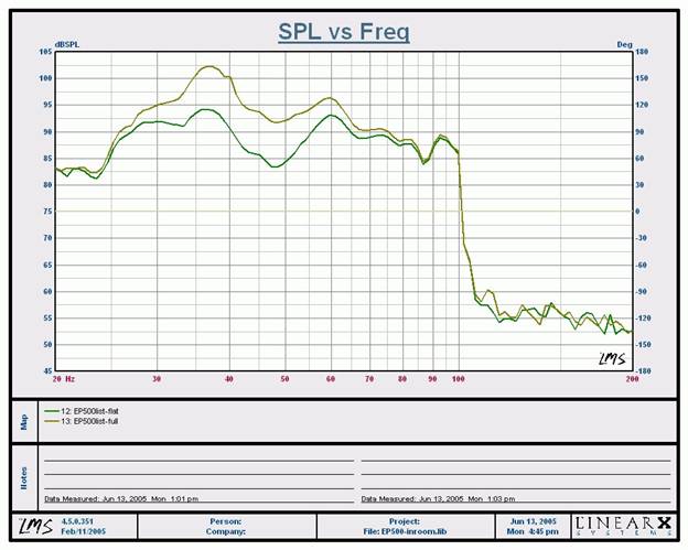
Lastly, there is a very cool "Trim" feature on this sub, which serves like a subwoofer EQ to tune the frequency response of the sub to your room. Options include: Flat, Half, Full, Load and Remote. Flat does what it implies and provides the flattest frequency response for the sub while Half and Full provide an extra boost above 33Hz (which I found useful in combating a room null where I chose to locate the subwoofer). The Load setting is meant for direct access to the subs DSP and should not be used during normal operation. The Remote setting is a feature to be used with future Axiom electronics (boy I can't wait)!
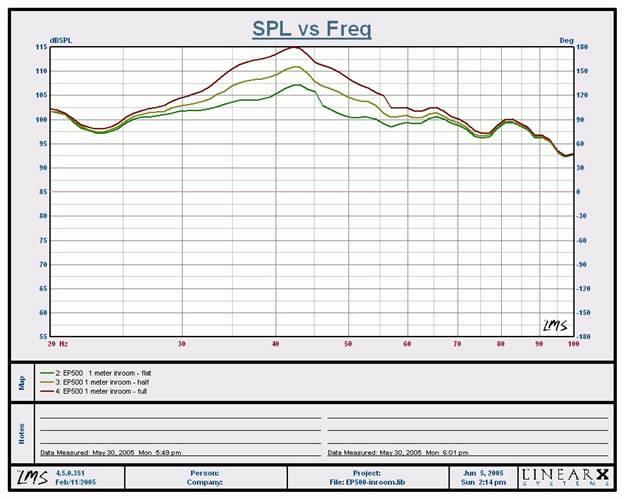
As you can see the green trace is the "Flat" setting, the yellow trace is the "Half" setting (applying about 6dB of boost centered at 44Hz), and the purple trace is the "Full" setting (applying about 10dB of boost centered at 44Hz).
But there is more to this sub than its phenomenal amplifier. The slightly more manageable box size of the EP500 measures in at 20 x 15 x 20 inches and plays down flat to 20Hz +/- 1.5dB with about 2-3dB less output than its bigger EP600 sibling. This is quite an impressive feat for a subwoofer of this box size and single 12" driver compliment. To get an understanding as to how this is done, a closer look into the mechanics of the driver, enclosure, and DSP processing is in order.
The Driver
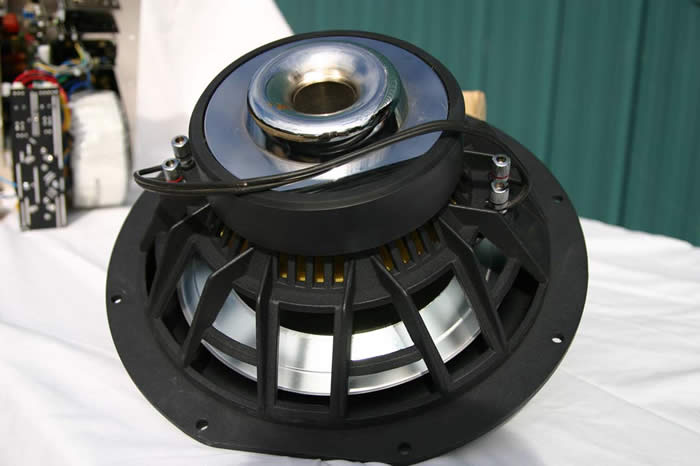 This is one heavy duty high-excursion subwoofer driver with a
huge motor structure, 3"
diameter dual voice coil, bumped back plate, and cast frame (no
Chinese stamped woofers here). This is the type of driver typically reserved for high output car
audio systems, except the cone stiffness is much higher than many of those designs, enabling a higher
degree of linearity and improved transient response.
This is the same driver found on the EP600
(the refrigerator sized flagship subwoofer from Axiom).
Thanks to the benefits of lower cost
with high volume, Axiom was able to incorporate this same driver design in all of the 12"
subwoofer systems including the EP350.
I was mildly disappointed to discover the driver
was not magnetically shielded.
Though, it's understandable since it would add significant
weight and size to this already massive driver.
My advice is to place this subwoofer away from
CRT based displays and don't sit to closely to this monster if you or grandma sports a pace
maker :-)
This is one heavy duty high-excursion subwoofer driver with a
huge motor structure, 3"
diameter dual voice coil, bumped back plate, and cast frame (no
Chinese stamped woofers here). This is the type of driver typically reserved for high output car
audio systems, except the cone stiffness is much higher than many of those designs, enabling a higher
degree of linearity and improved transient response.
This is the same driver found on the EP600
(the refrigerator sized flagship subwoofer from Axiom).
Thanks to the benefits of lower cost
with high volume, Axiom was able to incorporate this same driver design in all of the 12"
subwoofer systems including the EP350.
I was mildly disappointed to discover the driver
was not magnetically shielded.
Though, it's understandable since it would add significant
weight and size to this already massive driver.
My advice is to place this subwoofer away from
CRT based displays and don't sit to closely to this monster if you or grandma sports a pace
maker :-)
The Cabinet
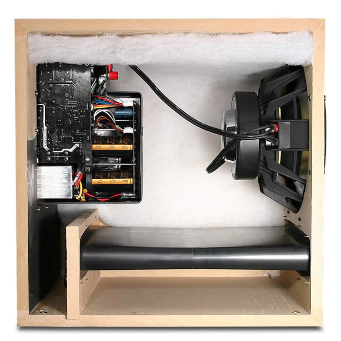 The EP500 cabinet is constructed from ¾ inch
thick
MDF with a cross bracing adjoining three
walls.
I would have preferred to see an additional cross sectional brace in the middle of the
cabinet adjoining all four walls, and incorporate kicker bracing at each mitered corner to add
additional support and further reduce resonance and the mechanical noise floor.
However, there
are often tradeoffs in adding more bracing such as using up more cabinet volume and complexity in assembling, thus designers must
determine what works best for a particular application with the least amount of compromises.
Its slot-loaded porting system measures almost 12 inches wide by 2 inches in height and extends over
19 inches into the cabinet.
The advantages of having such a large port opening are to minimize
port noise and chuffing during high output. It also enables a low port tuning to take advantage of
the driver's extension and high-output capabilities.
The EP500 cabinet is constructed from ¾ inch
thick
MDF with a cross bracing adjoining three
walls.
I would have preferred to see an additional cross sectional brace in the middle of the
cabinet adjoining all four walls, and incorporate kicker bracing at each mitered corner to add
additional support and further reduce resonance and the mechanical noise floor.
However, there
are often tradeoffs in adding more bracing such as using up more cabinet volume and complexity in assembling, thus designers must
determine what works best for a particular application with the least amount of compromises.
Its slot-loaded porting system measures almost 12 inches wide by 2 inches in height and extends over
19 inches into the cabinet.
The advantages of having such a large port opening are to minimize
port noise and chuffing during high output. It also enables a low port tuning to take advantage of
the driver's extension and high-output capabilities.
The port system of the EP500 in conjunction with the DSP processing is how the EP500 works its magic of providing unprecedented extension, slam, and output levels. Let's take a closer look at the porting system to gain a better understanding.
Axiom EP500 Port Tuning and Setup
Based on the closed/open port impedance measurements, you can see FH = 42Hz, Fc = 36Hz, FL = 14Hz, Fm = 24Hz and Fb = 25.8Hz and where Fb = (Fh^2 + Fl^2 - Fc^2)^1/2.
frequency
The relative similar amplitude peaks of FL and FH indicate good port tuning while Fm and Fb being only 1.8Hz apart is one attribute that demonstrates it to be a well-executed and linearly-tuned system.
For those who like to get down to the inner details of subwoofer designs, Mark Sanfilipo (our resident loudspeaker engineer) has provided the following equations in the editorial note below to determine a good first-order approximation of the box tuning based on the physical port dimensions we furnished to him on the design of the EP500.
Editorial Note on Port Tuning by Mark Sanfilipo (updated June 23, 2005 )
Driver Branch Enclosure Branch
First approximation electrical equivalent Simplified driver/vented box circuit
Driver Branch
Revc = voice coil DC resistance
Levc = voice coil inductance
Res = resistive electrical equivalent of suspension losses
Cmes = capacitive electrical equivalent due to the cone's moving mass
Lces = inductive electrical equivalent due to suspension compliance
Enclosure Branch
Lceb = inductive electrical equivalent of the acoustic compliance of air in the enclosure
Rel = resistive electrical equivalent of acoustic resistance of enclosure losses caused by leakage
Cmep = capacitive electrical equivalent of the acoustic mass of the port or vent, including air load.
The vented loudspeaker enclosure is a Helmholtz resonator. Ignoring for a moment the presence of the driver, this resonator is modeled here by the 2nd-order Cmep/Lceb/Rel series tuned-resonance circuit seen at the right side of the circuit pictured above. It's a very simplified electrical equivalent of a Helmholtz resonator.The driver (in combination with the enclosure) forms the basic system. It's modeled here by the 2nd-order Res/Cmes/Lces parallel resonance circuit, along with Revc & Levc, as seen in the center and left portion of the circuit pictured above. It too is very simplified.
The acoustical inertance provided by the air within and very near both entrances of the port, along with the compliance of the air enclosed by the cabinet, together form a resonant system. The system's driver forms a second resonant system. Together, they form the 4th-order vented box loudspeaker.
At their respective resonance frequencies, the driver branch hits an impedance peak and the enclosure branch hits a minimum. The two impedance peaks typically seen in the usual vented box Z-curve result from the enclosure branch's shunting the driver branch's impedance. The amplitude and shape of the peaks depend upon, among other things, both enclosure and driver losses.
When a given vented cabinet is tuned by altering port dimensions, the values of Cmep & Rel are altered. This, in turn, alters the impedance minimum of the enclosure branch that, running in parallel with the driver's parallel resonance tank, results in an impedance minimum unique to the interaction of the two branches. For most vented box systems, the enclosure branch resonance frequency resides (by design) in general proximity to the driver branch resonance frequency.
In the context of loudspeaker design, when reference is made to "fb" it's used to describe not the resonance frequency of the box as just a simple Helmholtz resonator, but the frequency to which the system is tuned. Though it seems counterintuitive, the frequency to which the system is tuned and the frequency where the inter-peak impedance minimum, fm, occurs by the driver & enclosure circuit branches running in parallel are not necessarily the same. Large voice coil inductance values can result in an fb higher in frequency than fm, for example.
Helmholtz Resonator Equation
fb = resonant frequency
C = speed of sound in air
r = radius of neck
a = area of neck
L = length of neck
L' = effective length of neck
k = correction factor, port with 1 end flanged, the other, not flanged. k = 1.4488 - 1.464 (common range of values)
L' = L + 1.4488r (outer end unflanged)
vb = volume of enclosureFrom Kinser & Frey's " Fundamentals of Acoustics "
fb = (c/2*pi) * [a/(L' * v)]^.5
= (179.845) * [a/(L' * v)]^.5EP500 Approximates
@ port depth = 19"
a = .1191 ft^2
r = 0.1947 ft
l = 1.58 ft
l' = 1.8622 ft
vb = 3.47 ft^3
fb = (s/2*pi) * [a/(L' * v)]^.5
= (179.845) * [a/(L' * v)]^.5
= (179.845) * [.1191/(1.8622 * 3.47)]^.5
= (179.845) * [0.1357]
fb = 24.42 Hz @ L = 19"

Set-Up
Moving around the EP500 proved to be a bit of a daunting task, not solely because of its rather hefty weight (nearly 70lbs) but because of its sheer depth. There was a point in my initial setup phase where I had the EP500 placed behind my couch and I needed to temporarily relocate it near one of my reference subs for comparative measurements. Out of laziness I physically curled this beast over my couch rather than opting to move the seating area. This is a maneuver I don't recommend but it does demonstrate that at least this sub is still somewhat manageable for moving around the room (either that or I am completely nuts - perhaps a bit of both).
I found the EP500 easier to place than most subs. Both myself and Ray Adkins are finding that the more linear the frequency response and bass extension a sub exhibits, the less fussy it is about placement to some extent. The EP500 makes it even easier with its variable trim settings. I settled on rear placement of the EP500 directly behind my listening position and found the "half" trim setting most appropriate to combat a room mode with the subwoofer placed in this location as indicated in the graph below.
Inroom Listening Position Measurement (unsmoothed)
By engaging the "Half" setting I minimized the frequency response dip between 42Hz to 50Hz at the primary listening position. Though it did provide more output from 35-40Hz, the overall summed response from all three subwoofers in my system helped to smooth this out. Using a PEQ to flatten the excessive output in the 35-40Hz region is certainly a valid measure to take for achieving the most accurate response.
Upon power up, I did notice an unusual amount of hum, which prompted the words "ground loop" to immediately pop into my head. Just when I was about to start tracing the source of the ground loop, I consulted the handy Axiom manual. It recommended to unscrew the little back panel screw for instances such as these. This physically floats the chassis ground and eliminates a current path between earth ground and the return line. I obliged and my ground loop problem was immediately resolved. Now, if only all of our daily troubles could be resolved this easily, the world would be a much happier place.
After several minutes of idle, I noted the EP500 back panel light remained illuminated green, indicating amplifier power was present. I questioned Axiom about this and they informed me there is no Auto On/Off feature on this sub, unless you utilize the 12V trigger connection. This was a concern to me at first until Axiom informed me the sub goes into auto mute mode when no signal is present, thus the power consumption is negligible since it's a Class D amplifier design. I opted not to use the 12V trigger since I didn't have one pre-wired for the location where I was testing this subwoofer.
Editorial Note on Auto Off (update 07/14/05)
In our investigative studies we actually discovered that there really isn't a true auto off on any powered subwoofer which doesn't have an independent DC trigger line. In reality most subs simply remove the connection between the power output devices and the subwoofer driver during the auto off state. But the power transformer and associated amplifier electronics are still active.
Most of the listening tests with this subwoofer were conducted with the EP500 configured as the dedicated LFE channel of my 3 subwoofer system powered by the Denon AVR-5805 multi-function receiver.
Axiom EP500 Listening Tests & Recommendations
All the measurements and pseudo jargon in the world can't convey how good a product is without some good old fashion listening tests. I must first make the disclaimer than I am a recovering Bassaholic. Though I have tried many 12 step programs to overcome my obsessive tendencies, none of them to date have been successful at satiating my appetite for deep powerful bass. Be warned if you have a weak heart or suffer from motion sickness, this may not be the right subwoofer for you. On the other hand, I quickly found Nirvana after a few listening tests and began feeling the quenching of my thirst for bass.
Multi-channel Surround


Blue Man Group "The Complex and Graham Nash" Songs for Survivors are two of my favorite multi-channel reference discs (if you haven't already gathered this from my mention of them in various reviews). The Dave Matthews track "Sing Along" from the Blue Man Group disc has excellent LFE content and the EP500 really showed it off. The bass was well-extended with oodles of punch and slam, especially towards the middle of the song with the mini drum solo. You could hear clear delineation of the bass notes, never sounding boomy or one notey as do some high-excursion subs. The DTS 96/24 percussion track really sounded wonderful on my reference system, even more so with the EP500 pumping out the LFE track. Adding the EP500 to my system really helped smooth out the bass response in my room while also providing significantly more low end extension and tactile response.
I rediscovered track #4, "Chelsea Hotel" from the Graham Nash DVD-Audio disc with the EP500. On my reference subs the bass was authorative and well-tempered, but with the EP500 thrown in the mix, slam and "felt" response was elevated to a new level. I enjoyed watching the EP500 rattle the plastic screen on my RPTV while it also rumbled my couch with authority. There were times I felt as if someone had installed tactile transducers under my couch and I actually had to convince myself otherwise. Track #9 "Liars Nightmare" blew me away the first time I heard it as I remember saying to myself "wow, that's really deep bass, atypical of most recordings". With the EP500 engaged, the hairs stood up on my arms as I felt the adrenaline rush from the power of the mighty sub. The EP500 handled multi-channel music with aplomb, never faltering or whimpering when pushed to levels loud enough to implode small furry animals.
Home Theater


Let's face it, the main driving force behind owning a subwoofer is for the movie watching experience and wow effect. An action movie is sterile without surround sound, and possibly worse if devoid of deep and powerful bass. I can't count how many times I have walked away from a local Cineplex disappointed from the movie watching experience because the sound system had anemic bass response and/or highly compressed and distorted bass on pivotal action scenes. Terminator 3 is a prime example of a movie that was much more enjoyable when viewed from home on my reference system than it was at any of the movie theaters I originally watched it at. There are too many good action scenes from T3 to discuss in this review but I will say the truck chase and bathroom fighting scenes were the two most memorable for me. The EP500 added much more realism and envelopment to the experience. At times I actually though I could hear Arnold's thoughts emanate from the EP500: "Gene, this is NO girlie man sub. It is very pumped." Who am I to argue with the Terminator.
Just for kicks I popped in a DVD I haven't watched for some time to see if the EP500 could further enhance my enjoyment of the movie. In Toy Story 2.I jumped to the opening scene where Buzz Lightyear was blasting his way to a planet tracking down Zurg. The first few minutes of this movie are simply stunning, both visually and audibly. The bass from Buzz's rockets and the smashing of Zurg's evil robot minions is nothing short of exhilarating. With the EP500 fired up, I proceeded. I found that my butt got a rather vigorous workout while the EP500 shook my couch to the sound of Buzz's rocket thrusters. I felt every bone crushing head decapitation blow Buzz dealt Zurg's evil robots with his laser. Even the music from the 2001 Space Odyssey while Buzz was walking through Zurg's fortress carried more weight and feel to it than I have previously heard. While my intention was to just skip through a few scenes in this movie to assess the EP500's performance, before I knew it I watched the movie in its entirety.
No matter what movie or music disc I threw at the Axiom EP500, it provided a newfound sense of realism and enjoyment that I didn't even know was missing.
Suggestions for Improvements
It's a bit difficult to find faults in such a high performance, high value product, but as Audioholics, we do our best to be overly critical. With that, here are a few bullet items I would like Axiom to consider to make their product even better:
- Thicker baffles and construction (this product, just like the entire Axiom line) uses ¾ inch MDF. We would prefer to see 1 inch thick on front baffles, especially on a subwoofer to reduce cabinet resonance.
- More bracing, especially on the bigger EP600 which sounds a bit hollow when wrapping on the sidewall.
- Round the edges of the cabinet (the boxy look just doesn't cut it these days)
- Offer a grill that connects directly to the woofer's screws so the bottom port is visible (it just looks too cool to hide away behind a grill)
- Magnetically shield the driver's though this would increase the weight of the driver significantly and also increase volume occupancy of the cabinet.
It's a short laundry list, but it gives us something to look forward to checking out on future Axiom subwoofer products.
Recommendations
The EP500 is one truly powerful subwoofer, capable of very high SPL levels, especially in smaller rooms. We recommend securing any expensive china or knickknacks before firing this bad boy up for the first time. Due to its very linear low frequency extension, output capabilities, and EQ options, the less fussy placement nature of this subwoofer is quite invaluable. However, experimentation is always key. Following the guidelines we have established in our Loudspeaker Setup Tips Pages is certainly a good start. The manufacturer's guidelines and Axiom Audio tech articles available at their site are also great resources to tap into for ensuring you squeeze out maximum performance of this product.
Although I achieved very good results locating this subwoofer behind the listening position, I would advise caution when attempting this type of configuration. Due to the high output and low extension characteristics of this subwoofer, I found it at times to be localizable, even with the LPF set to 80Hz. What was actually happening was that the enormous tactile effects and sense of pressure waves were distracting me enough to perceive there was a subwoofer somewhere in close proximity to me. I ultimately found pushing the sub back a few additional feet and off-center to the primary listening positions, lowering the output a few dB below reference to the rest of my system, and tweaking the crossover down a tad, helped to alleviate localization issues.
I have now listened to the EP500 in two completely different listening environments and systems. The first was my factory tour to Axiom Audio nearly a year ago, and the most recent was when integrated into my own reference system. In both instances, the EP500 proved to be an outstanding performer regardless of price. It had the ability to command the respect of any bassaholic whether their preferences lean towards home theater or music. Its almost limitless dynamics and tactile response aren't necessarily the defining characteristics that lend the EP500 to be an awesome subwoofer. Its low level linearity and control at high output levels really are the icing on the cake. There are many great subwoofers (especially available online) at this highly contested price point that offer commendable performance and cosmetics, but we feel the EP500 is class leading in performance in this price category. Alas "King of the Deep" is an appropriate title for it. If you are serious about bass, you owe it to yourself to check this subwoofer out. With Axiom's great customer service (one of the best we have seen in this business) and generous 30 day return policy, it's a risk free, no-brainer decision in this humble reviewer's opinion. In fact, if you aren't happy with the performance of this sub, please send it my way, my reference system could always benefit from the addition of an EP500 or two.
The toughest choice about the EP500 isn't debating its performance edge over the competition as much as it is figuring out which of the four standard finishes and two grill colors to choose from. As if that wasn't difficult enough, for a small premium there are even custom finish choices with six different grill color options . Now that's custom!
Axiom EP500 Performance Tests
While subjective commentary can give good insights as to how a product performs and how the listener/reviewer perceives its performance within the confines of their listening environment, the proof is in the pudding so to speak. This is why it's always good to have some supplementary measurements and analysis to see if those measurements correlate to what we are hearing. Since frequency response can demonstrate the product bandwidth or tonality, this is a good start.
To go one step further, one must test this frequency response at various power levels to determine power bandwidth uniformity and freedom from excessive compression. With that in mind, we ran some frequency vs SPL tests (borrowed from our First Look Article ) on the EP500 at various output levels to validate Axiom's claim quoted below:
"Our DSP system wants things to go smoothly all the time - no bumps in the road. Using a digital roadmap, the XLF controls every frequency from 17Hz to 100Hz, never deviating more than +-1.5dB through this entire range."
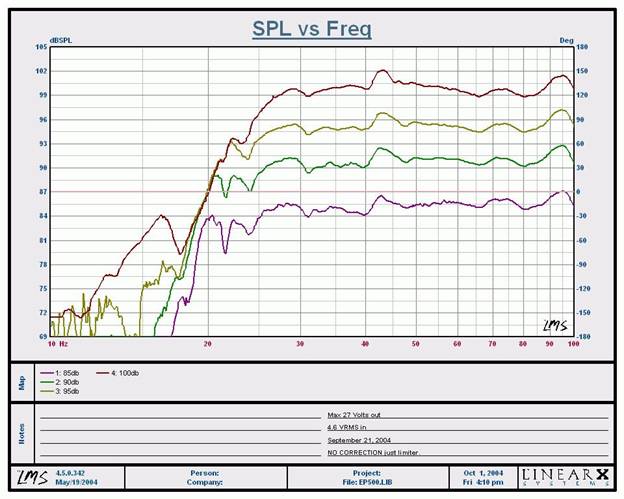
EP500 SPL vs Frequency Plots 1 meter 4pi measurements
Thus the Axiom Audio claim about maintaining +/-1.5dB 20Hz to 100 Hz for the EP500 through the entire range is in fact true providing that the SPL output is kept to around 80dB (anechoic) which equates to about 91dB in a real room or +/-3dB under 92 dB (anechoic) which equates to about 103dB or so in a real room.
Editorial Notes on 4pi and 2pi Steradians Environments
4pi steradians describes a complete sphere. 2pi steradians describes a half a sphere or hemisphere. Therefore, when we measure outside on a pole we say we're measuring in 4pi. Or if we've got an anechoic chamber with a wire floor so that we are completely surrounded on all six sides by big ole fiberglass wedges we say that's 4pi. If we have a chamber with a hard floor into which we put a baffle and speaker, with the other five surfaces being those fiberglass wedges then that's 2pi. This is one way to measure an in-wall speaker. Similarly, if we go outside, dig a hole and put a speaker-in-a- baffle over that hole and shooting up, then we're measuring in 2pi.
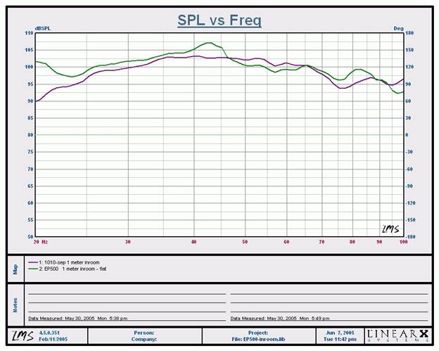
1 meter in room measurement (ground plane technique, unsmoothed)
The green trace represents the EP500 while the purple trace is from my reference sub, the RBH 1010-SEP. Notice the EP500 has significantly more output below 25Hz. You can see the slight dip at the box tuning frequency of 24Hz in the EP500, but then the driver response below tuning is linearized via DSP processing to help extend the low frequency range. I noticed a slight bump of about 3dB centered at 44Hz, the second impedance peak in the open port response. I am uncertain of its cause and could only speculate that it indicates slight system overshoot which isn't uncommon with high mass drivers such as the one used in the EP500.
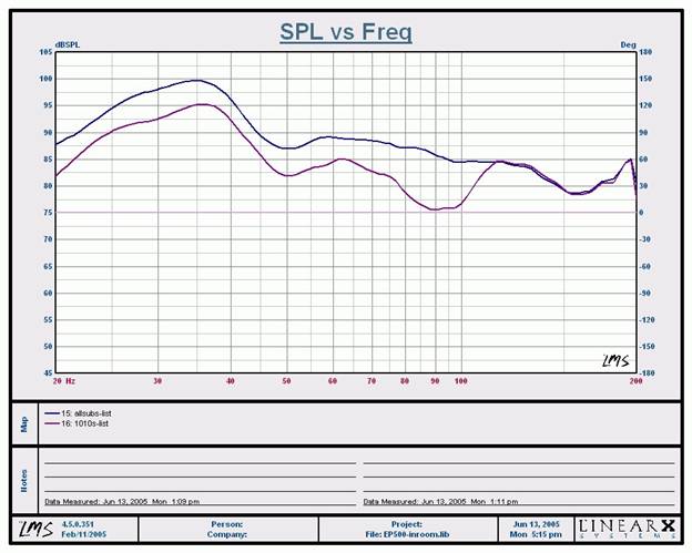
The purple traces represent the bass response of my dual RBH Sound 1010-SEP subwoofers while the blue trace represents all three subwoofers (dual RBH 1010-SEP's and the Axiom EP500). Notice the dip between 80Hz and 100Hz is virtually eliminated by adding another subwoofer into my system. Ideally four subwoofers strategically placed though out the room would yield bass nirvana for virtually all listeners, but three subs seem to do commendably well also.
Axiom EP500 Conclusion
The Axiom EP500 subwoofer is in my opinion the best value subwoofer in their product line. It gives up only a little performance (mostly low end extension) to it's bigger EP600 brother but it's also in a much more manageable form factor. After hearing both EP500 and EP600s side by side at the Colquhoun home, I actually preferred the more musical nature of the EP500. Cosmetically the design of this sub is a bit bland and boxy but if you tuck it in a corner or behind a sofa, it shouldn't be much of an issue. With Axiom's excellent customer service, tons of finish options and a generous return policy, you may just want to give it a try.The Score Card
The scoring below is based on each piece of equipment doing the duty it is designed for. The numbers are weighed heavily with respect to the individual cost of each unit, thus giving a rating roughly equal to:
Performance × Price Factor/Value = Rating
Audioholics.com note: The ratings indicated below are based on subjective listening and objective testing of the product in question. The rating scale is based on performance/value ratio. If you notice better performing products in future reviews that have lower numbers in certain areas, be aware that the value factor is most likely the culprit. Other Audioholics reviewers may rate products solely based on performance, and each reviewer has his/her own system for ratings.
Audioholics Rating Scale
 — Excellent
- — Very Good
- — Good
- — Fair
- — Poor
| Metric | Rating |
|---|---|
| Bass Extension | |
| Bass Accuracy | |
| Build Quality | |
| Fit and Finish | |
| Ergonomics & Usability | |
| Features | |
| Performance | |
| Value |
Gene manages this organization, establishes relations with manufacturers and keeps Audioholics a well oiled machine. His goal is to educate about home theater and develop more standards in the industry to eliminate consumer confusion clouded by industry snake oil.
View full profile