
Klipsch THX Ultra2 Loudspeaker System Review
Klipsch THX Ultra2
- Product Name: THX Ultra2
- Manufacturer: Klipsch
- Performance Rating:


- Value Rating:
- Review Date: May 16, 2006 20:00
- MSRP: $ 10,750
|
KL-650-THX LCR Speaker Sensitivity (2.83 V/1m,
averaged, from 300 to 3000 Hz):
|
97.0 dB spl |
|
KL-525-THX Back Surround Speaker Sensitivity (2.83 V/1m,
averaged, from 300 to 3000 Hz):
|
94.0 dB spl |
|
KS-525-THX Side Surround Speaker Sensitivity (2.83 V/1m, averaged, from 300
to 3000 Hz):
|
96.0 dB spl
|
|
KW-120-THX Subwoofer Rated Impedance:
|
8 Ω
|
|
KA-1000-THX
Amplifier
|
|
Pros
- Tonally neutral
- THX Ultra2 certified
- High efficiency
- Dynamic sound
- Authentic detail resolution
- Excellent placement flexibility
Cons
- Boxy-shaped cabinets
- Protruding binding posts on the KS-525 requires relief cutout to accommodate flush mounting
Klipsch THX Ultra2 Company History
For nearly six decades Klipsch Audio Technologies has held an enviably successful position in the American consumer audio industry. That sort of longevity (given the competitive, volatile nature of the speaker biz) is, in and of itself, a tremendous and rare accomplishment. That their success has come about with a product line focused on horn-loaded loudspeaker systems for both the pro and home audio use makes this achievement even more impressive. And Klipsch knows horns; some of the best & brightest loudspeaker engineers, both past & present have contributed their talents to the Klipsch product lines over the years. And it all began with one person, with an idea, and a rented tin shed in Hope, Arkansas.
Klipsch THX Ultra2 Build Quality
The Ultra2 arrived as a pretty impressive pile of boxes, comprising 10 shipping cartons. Packed inside the cartons were three KL-650-THX (LCR), two KL-525-THX, (back surrounds) two KS-525-THX (side surround) speakers, two KW-120-THX subwoofers and one KA-1000 power amp.
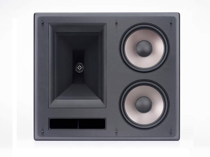
Figure 1: KL-650 THX without and with grill cover
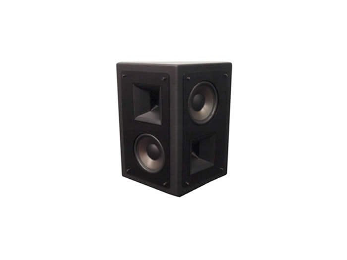
Figure 2: KL-525 back surround and KS-525 side surround, grille covers off.

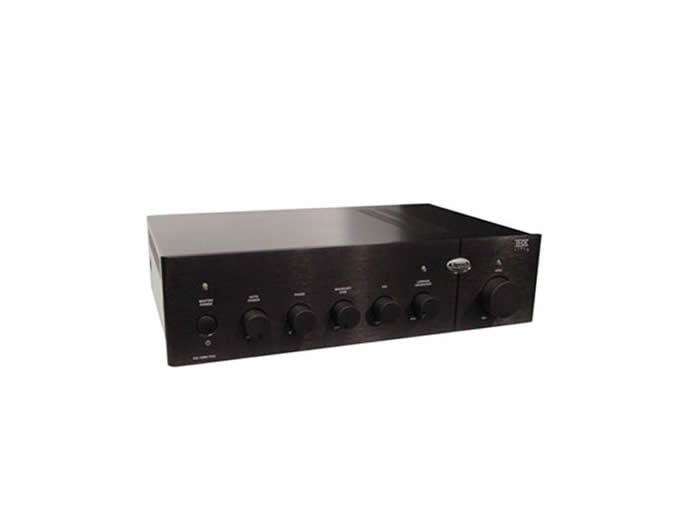
Figure 3: KW-120 subwoofer and KA-1000 2-channel subwoofer amplifier
Each item was shipped housed in its own carton, well-braced internally with Styrofoam and wrapped in a protective cover. In Figures 5a - e we see the unpack sequence for one of the KW-120 subwoofers, illustrating Klipsch’s approach to product packaging.


Figures 5a - e: Klipsch KW-120 Product Pack
 Note top & bottom
Styrofoam inserts stabilizing the KW-120 within the carton, cardboard edge
bracing, the essential plastic & foam wrap around the unit itself and the
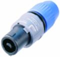
inclusion of the Speakon connector-tipped speaker cable. (More on the included
cable later).
Note top & bottom
Styrofoam inserts stabilizing the KW-120 within the carton, cardboard edge
bracing, the essential plastic & foam wrap around the unit itself and the
inclusion of the Speakon connector-tipped speaker cable. (More on the included
cable later).
Once out of their cartons you’re no doubt going to be impressed by the appearance of these loudspeakers. With or without grille cloth they look great! Industrial art would be an apt description. Surprised to read of a plain box cabinet being referred to as “art”? It’s the finish that makes all the difference in this case. The appearance of the Galaxy Black finish featured in the Klipsch THX Ultra2 system cannot be captured in a photo that does justice to its striking beauty. Both aesthetically pleasing and functional, the choice of this particular finish with this system was brilliant. How so?
Aesthetically speaking, the Galaxy Black finish has a subtle way of lessening the visual impact of having 9 speakers clustered together in a home theatre. The finish is somewhat lighter than straight piano or charcoal black, not uncommon colors in the world of loudspeakers. Less stark than either piano or charcoal black, the finish is nevertheless dark enough to ensure the speakers present minimal visual distraction.
Inside Look
For the inside look we’ll use one of the KW-120 subs as the specimen of interest.
Peeling off the grill cloth, the sub appears pretty much as seen in Figure 3 above. The four studs to which the grill cloth is attached are actually the heads of the 4 bolts holding the aluminum fascia in place. Removing the fascia we can then remove the driver.
I laid the KW-120 on its back and proceeded to remove the bolts securing the driver in place. Once I had removed them all, I found the driver at first wouldn’t budge. It seemed like the thing was stuck in place. As it turns out, it wasn’t stuck at all. In actuality I had encountered a driver that was far, far heavier than I had anticipated. I haven’t weighed the driver and cabinet separately, but it wouldn’t surprise me at all if the driver turned out to weigh more than the substantial cabinet into which it is normally bolted.
Figure 7a – b: KW-120 Subwoofer Driver
Figures 7a - b are a couple images of the driver extracted from the cabinet, now sitting on top of it. Once out of the cabinet it was easy to see why the unit was so weighty. The motor assembly is an interesting structure with an interesting history. Kerry Geist, an engineer at Klipsch, wrote in response to my question regarding the possibility the motor assembly was originally designed for use in a larger drive:
“Yes, the KW-120 uses essentially the same motor assembly as one of our 15" subwoofer drivers. However, the motor structure was further improved by adding a copper shorting ring to the yoke to reduce the distortion caused by variations in voice coil inductance. The advantage of using an existing motor design was simply a matter of using a design we already had experience with, and felt we didn’t need a huge engineering effort to develop into a 12” high-displacement version. We already had plenty of engineering hours wrapped up in the original 15” design...we were just using that “developed” platform as a jumping off point to develop the 12” THX version. The displacement and power handling requirements between the two drivers were very similar...it was an easy choice to make. Other than the shorting ring modification, I’m not aware of any other changes to the motor assembly itself. The soft parts of the driver (cone, suspension, dust-cap, etc…) and housing were different of course. As far as I can remember, the voice coil design is different, but they’re both based around a 3” diameter / 2” coil length format.”
Looking inside the now driverless cabinet, we get a great view of the interior. (Though not evident in any of the photos, the faceplate is double-thickness). There are a number of interesting features.
Figure 8a - b: Klipsch KW-120 Cabinet Interior
The cabinet is cross braced. The brace itself spans the top, bottom and side panels. It also serves to secure the substantial motor structure of the driver. The brace, along with the cabinets various panels, are reinforced with glue blocks placed throughout.
In the background of Figure 8a - b can be seen the interior end of the cabinets duct. The exterior end of the duct can be seen at the top of cabinet’s faceplate in Figure 3. The duct is in fact a collection of panels built into the interior of the cabinet, running parallel to the top and back panels. The interior end of the duct opens at a point just above the Neutrik input jack position on the back panel. The duct also serves as a useful handhold, which comes in handy when its time to move the cabinets around. The cabinets were not stuffed.
Klipsch THX Ultra Setup and Listening Tests
Each carton was maneuvered to a spot on the home theater floor approximately where each speaker would eventually find its final location. Each item was quickly & easily unpacked and the cartons stowed away elsewhere.
There are a number of guidelines (many available online) which provide ample
guidance for setting up a THX-certified home theatre system. In this case, you won't have to look
far for setup "How to's"
as the Owner's Manual provides all the basics in terms
of properly arraying the speakers around your listening space. The actual final position for the
various speakers making up the system was very much like that shown in Figure 9, with the exception of
the two subwoofers: In the end they were positioned directly beneath the front L
&
R
speakers.
If you plan on mounting the KS-525s flush against the wall be prepared
to carve out a relief cutout so as to accommodate the protruding binding
posts.
Figure 9: Speaker disposition as suggested by Klipsch Manual
Editorial Note on Subwoofer Placement
Subwoofer placement can be a tricky business. Fortunately, there are readily available many resources - codified as recommendations, practices or standards to assist in choosing the best location for your sub Of course, there' s always available the wherever-they-sound-best-to-you approach. But if you're interested in applying a more organized approach to subwoofer placement, have a look at:Subwoofer Placement Guidelines
Subwoofer Calibration - The Place for Bass Part 1
For helpful information about THX in general see also:
THX Select and THX Ultra2 Certification General Questions
Listening Tests
Walk into a Hard Rock café or a Malco, Krikorian, Harkins, Clearview, United Artists, or Regal cinema anywhere on planet Earth and you will likely hear Klipsch systems in action. Go see a concert in an arena or stadium and you will hear horns in action. It seems quite sensible - the idea of bringing the horn-loaded systems technology used in commercial cinemas into a home theatre setting. How well does it work in practice?
The 5 DVDs (and CD) listed below were chosen from several dozen disks that were used during the course of the review sessions; each chosen because in one way or another they demonstrated various individual performance characteristics that when taken together conveyed a sense of the system's overall performance.
 Top Gun
, sounded like, well, Top Gun, a movie made twenty
years ago. I happened to be living in southern California when the movie was first released and I saw
it a couple of
times in LA and Orange County.
Top Gun
, sounded like, well, Top Gun, a movie made twenty
years ago. I happened to be living in southern California when the movie was first released and I saw
it a couple of
times in LA and Orange County.
At one point in the movie there's an audio scene where the sound of a fighter jet pans overhead, crossing the listening area. In those LA and Orange County commercial cinemas the pan sounded clear, focused and smooth. Another words, it worked. My experience has been that lesser systems tend to botch the pan, typically sounding like the jet simply faded out in one part of the soundstage and faded in at another, without the audible sense of it crossing smoothly between the two points.
I was particularly interested to see how the Klipsch system would handle the pan, specifically because
 of the horns used in the systems - including the back
&
side
surrounds. Horns are synonymous with controlled dispersion, yet current surround sound thinking
indicates a diffuse sound field for the surround channels is essential for authentic rendering. It
would seem that controlled dispersion and diffuse sound fields are a means contradictory to the ends.
The Klipsch solution? Wide dispersion Sound Technology (WDSTTM). According to Klipsch, "By
aligning two horns at 90° with respect to each other, along with a front-firing woofer, WDST surrounds
smoothly cover a 180° horizontal arc. The surround points at you no matter where you are seated,
drawing you into the middle of the action
."
When put to the test, WDST worked and the
Klipsch sailed through this challenge with ease; the pan was just as clear, focused and smooth as it
was intended to sound.
of the horns used in the systems - including the back
&
side
surrounds. Horns are synonymous with controlled dispersion, yet current surround sound thinking
indicates a diffuse sound field for the surround channels is essential for authentic rendering. It
would seem that controlled dispersion and diffuse sound fields are a means contradictory to the ends.
The Klipsch solution? Wide dispersion Sound Technology (WDSTTM). According to Klipsch, "By
aligning two horns at 90° with respect to each other, along with a front-firing woofer, WDST surrounds
smoothly cover a 180° horizontal arc. The surround points at you no matter where you are seated,
drawing you into the middle of the action
."
When put to the test, WDST worked and the
Klipsch sailed through this challenge with ease; the pan was just as clear, focused and smooth as it
was intended to sound.
The Hendrix DVD was chosen for the dialog that runs throughout much of the movie. Dialog can be quite a challenge for any speaker system; particularly so for those systems that make use of horns. Lesser quality horns (or even top quality horns used incorrectly) impart a nasally, honky quality to dialog. Occasionally you'll even hear this in theatres that otherwise deliver superb sound to the listener.
I didn't hear the Klipsch system impart any sort of annoying nasality or honkiness to any of the dialog at any point in the movie. This was, of course, in part due to the decent gear upstream of the speakers. But the lions share of credit needs to go to the Klipsch speakers. With a respectably smooth response, the judicious choice of crossover points (measurements below) and the functional abilities of a Tractrix horn, its understandable how a horn-loaded system could deliver such a high quality subjective impression.
 The dialog was consistently natural, engaging, and very clean.
Top quality sound systems are ruthless in exposing poor quality media. Ask anyone who owns one and they will tell you how quickly such a system will reveal a particular recording's faults & flaws. Rush's R30 DVD is an example of just such a recording.
Prior to auditioning the DVD using the Klipsch system I had listened to it a few times on a very average system and the DVD sounded average; nothing especially good or bad about it. Played back on the Klipsch system and the impression was altogether different. The Klipsch revealed the audio tracks as sounding very, very heavily compressed, taking away much of the dynamics that are a critical part of the excitement of live entertainment - or attempts to reproduce the moment in a home setting.
Enjoy the Rails! is a CD that has lately become a favorite of mine for testing subs. It's an interesting disc, comprising a collection of well executed recordings of diesel locomotives, made at close range and with a bare minimum of processing. That's a combination likely to appeal to both audio purist and railroad enthusiast alike.
 If you've ever stood beside railroad tracks as a diesel locomotive
thundered by you'll be familiar with the earth-jiggling power of these mechanical giants. All the
recordings contained in the CD were made at a distance of 1 -
3m meters and carry sustained,
substantial amounts of just the sort of LF
&
ELF content that subs are made to reproduce. Even if
you're not a railroad enthusiast, these are exciting recordings to listen to.
If you've ever stood beside railroad tracks as a diesel locomotive
thundered by you'll be familiar with the earth-jiggling power of these mechanical giants. All the
recordings contained in the CD were made at a distance of 1 -
3m meters and carry sustained,
substantial amounts of just the sort of LF
&
ELF content that subs are made to reproduce. Even if
you're not a railroad enthusiast, these are exciting recordings to listen to.
Played back through the pair of KW-120s, the tracks shook the immediate vicinity just as you'd expect a diesel locomotive to do if it were passing by a few meters away. There was an almost palpable "realness" to the sound filling the listening space and the subs quite capably defined the presence of those hundreds of virtual tons of heavy metal trundling through the room.
Of all the loudspeakers comprising the Klipsch THX Ultra2 system, the subs were the biggest surprise of all. They look so utterly civilized , yet when called to duty they can kick & roar with masterful authority. As capable as they are at dumping eye-popping amounts of acoustical energy into a listening space, they don't overwhelm or overplay as some subs tend to do. They don't butt in to audio scenes where they don't belong. They integrate seamlessly with the rest of the system and having two cabinets helps immensely when it comes to finding suitable placement when dealing with room modes.
Klipsch opted to build the power amp separate from the subwoofer cabinet; the amp is a stand alone unit that jacks into the subs via the supplied 6m (20') long, Neutrik Speakon plug tipped, cables (See Figure 5b).
Providing a separate power amp is a major convenience, and especially helpful for those who opt to build their system into the walls of their home theatre. Even if you have no plans to build your speakers into or onto the walls of your home theater, racking up the KA-1000 along your AV receiver provides other benefits: If you've spent too much time crawling around behind your sub tweaking this or that setting, perhaps by flashlight, you'll especially appreciate having the sub's power amp close at hand. No more hanging out behind your sub in that forgotten zone where dust, lost toys and the occasional house pet gather while you tweak away in search of the perfect splice.
The cable that comes with the subs is worth mentioning in further detail. They cables sport, as already mentioned, Neutrik Speakon plugs. I see these connectors used all the time in pro audio situations. This, however, is the first time I have encountered them in a home audio application. Excellent! The cable is made up of four 16 gauge wires, paired at the connector end, resulting in a very flexible 13 gauge cable.
 The Neutriks are sturdy, pretty much foolproof, can handle prodigious
amounts of current (30 A!) and feature self-cleaning contacts. This is yet another example of the nice
(functional) touches found in the Klipsch Ultra2 THX system that help separate it from run of the mill
products.
The Neutriks are sturdy, pretty much foolproof, can handle prodigious
amounts of current (30 A!) and feature self-cleaning contacts. This is yet another example of the nice
(functional) touches found in the Klipsch Ultra2 THX system that help separate it from run of the mill
products.
If I had only one DVD by which to review this system Eric Clapton's Sessions for Robert J. would be my choice. The DVD from the two disk DVD/CD suite thoroughly explores the outer reaches of the Ultra2 THX system's performance envelope, giving the system the chance to showcase its talent to the max.
Each of the four previously mentioned discs illustrated individual components of the system's performance abilities. The Sessions for Robert J . DVD would help provide the answer to the all-important, over-arching question: how authentic a reproduction is this system capable of delivering? All the right ingredients were certainly in place for the magic to happen once "Play" was pressed.
The Sessions for Robert J. DVD/CD suite is a collection of material originally written & performed in the 1930's by Robert Johnson, an American blues musician, now performed by Eric Clapton and company. The production values found in this compilation are excellent, as is the musicianship. The tracks were recorded at four separate locations, a recording studio in England, a studio in Irving, Texas, a now-abandoned film distribution building in Dallas and a beach front hotel room in southern California.
Once I'd gotten hold of a copy of the DVD it went straight to the top of my play list. Simply put, no other DVD gave the Ultra2 THX system the chance to show off its stuff like this one did. The collection of tracks done at the top of the DVD sounded so authentically lifelike when played back through the Klipsch that I found myself viscerally reacting as though I were sitting through the zillionth sound check of my sound guy career in my home theater!
Right at the top of "Sweet home Chicago" track they set hi-hat levels with Eric shouting instructions back to the board op as the drummer tapped out measure after measure of kick/snare/high-hat. I kept listening to that segment of the track over and over at levels typical for a band playing in a space the size of the studio it was recorded in. The more I listened, the more apparent it became the Klipsch speakers were reproducing a musical event, in a way, that at times, sounded closer to the real thing than I've ever heard a home theatre system do before. All the benefits to be gained in using horns - controlled dispersion, higher than average sensitivity and low distortion (so long as they're not pushed to hard) - came into play here and contributed to the authenticity of the moment. What a tremendous technical achievement. My hats off to all at Klipsch who played a role in designing and/or manufacturing this superb loudspeaker system.
Now what about the "so long as they're not pushed to hard" bit? Any horn, pushed too hard, will spray the listening area with obnoxious amounts of distortion. You've probably been exposed to just this type of horn-pushed-too-far distortion last time you saw an arena concert played through a too-small system, paired back, perhaps, to keep expenses down. If management deems it necessary to leave half a semi's worth of FOH (front of house) speakers behind then everything that's left has to work all the harder to keep levels up. Ouch!
What about the Klipsch horns? Yep, they can be pushed into the obnoxious distortion zone, but only when driven at levels no one would want to expose themselves to for very long. Go back and look at those sensitivity figures again - this system knows how to play REALLY LOUD and enjoy every minute doing so - without having to be pushed into the obnoxious distortion zone. Indeed, in all the dozens and dozens of hours spent listening to this system I never needed to push the system into that particular zone. It was so capable of playing so loudly and cleanly without being pushed beyond its limits.
Klipsch THX Ultra2 Measurements

Figures 10 - 13 are impedance curves for the various systems making up the Klipsch Ultra2 THX home theater system. In Figures 10 & 13 we see the typical saddle-shaped curve at the left, with the impedance minimum (5.3 Ω @ ~ 56 Hz for the KL-650 and 6.7 Ω @ ~ 25 Hz for the KW-120) in each case indicating the vented box tuning frequency. In Figures 11 & 12, the closed box tuning frequency is indicated by the impedance peak (32.6 Ω @ ~ 83 Hz for the KL-525 and 41.6 Ω @ ~ 107 Hz for the KS-525). The second peaks, seen towards the right in Figures 10 - 12 typically arise as a result the interaction of the crossover network's high- and lowpass sections, setting up a parallel resonance.
The global impedance minimum for the KL-650, KL-525, KS-525, and KW-120 are (respectively): 3.2 Ω (averaged), 4.2 Ω , 3.6 Ω , and 6.7 Ω . The respective system nominal impedance (per IEC standards) are therefore 4 Ω , 6 Ω , 4.5 Ω , and 8 Ω . Obvious from the measurements, no system ever went below 3.2 Ω , as per THX requirements.
The impedance phase swings between +40° and -60° (KL-650), +41° and -64° (KL-525), +60° and -65° (KS-525), and -46° and climbing towards 90° (KW-120). The impedance minima might give cause for concern, but keeping in mind the phase angle at the minima and the high sensitivity of the KL-650, KL-525, and KS-525 the systems shouldn't prove to be a difficult load for most AV receivers, especially THX Ultra2 certified ones.
Klipsch THX Ultra2 Measurements (cont.)
Figures 14, 16, 17, and 18 show the amplitude response of the frequency response of the KL-650, KL-525, KS-525 and KW-120 systems, obtained by the application of gated, near field and ground plane measurements, as appropriate, scaled to 1m.
The relative flatness of the response curves (particularly with the KL-650 & KL-525s) underscores the tonally balanced & sonically accurate presentation of this very impressive system. It's easy to see how
the musicalness (ability to accurately render the timbre of individual instruments) of the system is as outstanding as it is.
The grill cloth used by Klipsch is, acoustically substantially, substantially transparent. Figure 15 shows a comparison between dB spl measurements made with and without grill cloth in place. A perfectly transparent grill cloth would have produced a ruler-flat line, centered at 0 dBr. As it is, the curve is very flat and better than some I have seen of systems costing far more than the Klipsch Ultra THX2.
The KW-120 were measured outdoors, using the ground plane technique. The initial measurement was made at 2.828 Vac drive level and increased incrementally. The dB spl curves showing in Figure 18 are for 1 sub, Figure 19, 2 subs. (Note: some of the curves look messy in the 10 - 15 Hz segment; this is due to environmental noise and should be ignored).Pairing 2 KW-120s and firing their combined acoustic output into 1/8th space (ie, 2 KW-120s placed side by side in a corner of a listening room) and the dB spl levels listed in the Klipsch spec sheet are reasonably obtainable.
Klipsch THX Ultra2 Conclusion
The THX Ultra2 is simply amazing in terms of sheer musicalness, its ability to deliver exceptional dynamics and clean, unadulterated detail. It's a system that proves once and for all you can bring, in an authentic way, the big-screen cinema sound experience to your home. It will again and again surprise you in ways that define the exceptional listening experience. The Klipsch Ultra2 THX 7.1 home theater system gives the consumer the opportunity to reap the benefits of a product built on 60 years of engineering expertise and technological refinement all in a package that can fit into your home theater.
With the THX Ultra2, Klipsch have managed to carry forward decades of home & professional cinema sound experience and bundle it all into one brilliantly executed system. If you're ready to move up to a THX Ultra2 system and plan on making the rounds of all your local audio salons with audition list in hand, put this system at the top of that list. You'll save yourself an awful lot of audition time.
Klipsch THX Ultra2 Home Theater Loudspeaker System
MSRP: $10,750 Complete 7.1 System
For more Information, visit:
Klipsch
The Score Card
The scoring below is based on each piece of equipment doing the duty it is designed for. The numbers are weighed heavily with respect to the individual cost of each unit, thus giving a rating roughly equal to:
Performance × Price Factor/Value = Rating
Audioholics.com note: The ratings indicated below are based on subjective listening and objective testing of the product in question. The rating scale is based on performance/value ratio. If you notice better performing products in future reviews that have lower numbers in certain areas, be aware that the value factor is most likely the culprit. Other Audioholics reviewers may rate products solely based on performance, and each reviewer has his/her own system for ratings.
Audioholics Rating Scale
 — Excellent
- — Very Good
- — Good
- — Fair
- — Poor
| Metric | Rating |
|---|---|
| Build Quality | |
| Appearance | |
| Treble Extension | |
| Treble Smoothness | |
| Midrange Accuracy | |
| Bass Extension | |
| Bass Accuracy | |
| Imaging | |
| Soundstage | |
| Dynamic Range | |
| Performance | |
| Value |