
Von Schweikert VR2 Review
- Product Name: Von Schweikert VR2
- Manufacturer: Von Schweikert Audio
- Performance Rating:

- Value Rating:

- Review Date: March 23, 2004 19:00
- MSRP: $ 2495
|
Engineering Principle |
Three-way, four driver system, with Transmission-line woofer design |
|
Size |
40" (102cm) tall x 8" (20.3cm) wide x 16" (40.7cm) deep |
|
Weight |
66 lbs (30 kgs) raw, 85 lbs (38.6 kgs) with sand, 95 lbs (43 kgs) with lead shot. |
|
Woofer |
Twin 165mm (6.5") composite cone Low-Distortion drivers. |
|
Tweeter System |
1" (25mm) fabric dome tweeter with soft resin damping layers, Low Distortion motor, Ferrofluid liquid cooling/damping, and long-throw voice coil and motor assembly. |
| Dampening System | Resonance Trap cavity provided for insertion of lead shot. |
|
Crossover |
Global Axis Integration Network, 4th order slopes using cascaded 1st order filters at 200 Hz and 2.2 kHz. Polypropylene caps and air cored inductors are utilized. All drivers are connected in phase. |
|
Ambiance Driver |
1" (25mm) soft dome tweeter with wave guide mounted at rear of the cabinet and Dimension Control for effects level adjustment, calibrated. |
|
Frequency Response |
25 Hz to 25 kHz, -3dB (+/- 1 dB in the midrange)? |
|
Sensitivity & Impedance |
87.5 dB @ one watt/one meter, anechoic. 90 dB in room. 8 ohms nominal, 7 ohms low to 20 ohms high. |
|
Power Handling |
20 watts minimum power, 200 watts maximum r.m.s., 500 watts peak. |
|
Wire Connection |
Five-way binding posts, fitted for 6mm spade lugs, with CE approved sheathing. Twin pairs are fitted, for bi-wiring or bi-amping. Jumper straps are supplied |
|
Enclosure Finishes |
Blond maple, dark red cherry, black ash, and African hazelwood |
Pros
- Excellent driver placement
- Well braced, stiff cabinet construction
- Mass loading chamber for lead shot
- Plinth, spikes and coins are standard
- Adjustable rear ambience driver
- Veneered front, bottom and top
- Fine Craftsmanship on the cabinet, especially the veneer
- Tight bass
- Low profile grill locks
- Reduced Cost based on lighter cabinet design
Cons
- Requires careful setup and placement to maximize performance
- Requires lead shot and decoupling from floor to optimize performance
- Mid-Range seemed forward sounding during very loud volume listening levels.
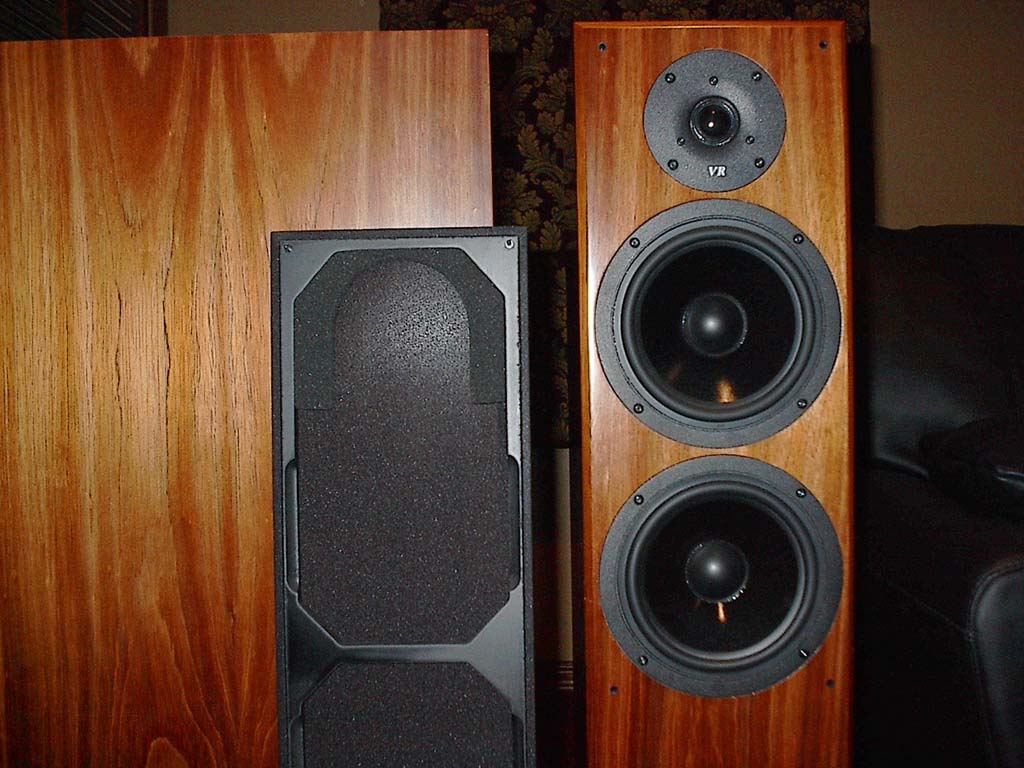
Von Schweikert Audio VR-2 Build Quality

The designers at Von Schweikert had some great goals in mind when creating the VR-2. Just to name a few, phase correction in the crossover, full frequency range, and my favorite, transparency. I wanted to remain as objective as possible in my approach to reviewing the VR-2 speakers so I did not read any reviews, entertain any user opinions, nor did I do any research on these speakers until I had experienced them first hand. On first sight I was very impressed with their appearance. Each speaker was covered with velvet to protect the finish and for us, it made them much more transportable as we moved them between Reference Systems . We unveiled the speakers from their velvet bag to reveal a beautiful African Hazelwood veneer. This was the same finish as the VR-1 Reference Studio Monitors which we reviewed several months earlier. Upon removing the grills I was happy to see that the people at Von Schweikert also covered the front baffle, top, bottom and back of the cabinet with matching veneer, especially since I listen to music exclusively with the grills off and away from the walls. The designers also used very small pin locks to fasten the grills which enhanced the beauty of these speakers even more because the pin lock holes were hardly noticeable from my sweet spot.
 The grills had a sturdy feel and the area around the tweeter has damping material for those of you who like to leave the grills on while listening. On the back of the speaker was a mid/tweeter which resembled a horn loaded dome and near the bottom was the adjustment for this ambience driver that allowed the rear ambiance tweeter to either be expressed loudly, or completely turned off. This made the speakers sound stage customizable to suite most tastes while also optimizing their performance to almost any given theater room. But we learned from first hand experience that these speakers do require time and care when installing in order to maximize their potential. This includes location, installing the plate and spikes to separate them from the floor, and adding the lead shot, all of which is outlined in detail in the 12-page owners manual.
Lead Bullets Anyone?
Under normal circumstances, we would question the need for adding the lead shot to a speaker. Upon lengthy discussions with Mr. Von Schweikert, it seemed we are not alone in questioning this requirement as many dealers and customers have asked the same. Based on our discussions with Mr. Von Schweikert and our own experiences with these speakers before and after the addition, we understood the logic behind this design concept.
The lead shot helped mass load the cabinet to the plinth which would normally done by a heavier cabinet like that found in our $10,000 Canton Karat Reference 2 DC Towers. Extra weight would in turn drive up the price of shipping, while also increasing the complexity to the cabinet design, which would drive up the labor and material cost of manufacturing. All these things would result in a much more expensive speaker to their customers. The lead shot was a reasonable and economic solution to mass load the cabinet and allowed Von Schweikert Audio to keep their entry level tower speakers at their $2,495 per pair intended price.
Mr. Von Schweikert informed us that more often than not, customers and dealers ask why Von Schweikert Audio doesn't sell the lead shot with the speakers. I loved his explanation where he stated that the shipping the lead shot would be more money then the lead shot itself, thereby resulting in the customer paying almost 3x the price compared to just buying it at a local gun store.
Leave the Sand on the Beach
Albert also indicated that there are reasons they recommend lead shot in place of sand. Sand has a significant amount of dust and traps water which could nurture mold, or even warp the cabinet over time.
VR 2 Speaker Construction
 At first look the VR-2's appear to be put together quite well. The front baffle was narrow which minimized diffraction. The tweeter was near the top of the cabinet at ear height and the midrange and bass drivers outer flange was right near the edge of the cabinet. This design should allow for excellent sound stage and imaging. Also note that the woofer was above the mid-point of the cabinet which helped avoid resonance's of the cabinet itself. After removing the midrange and bass driver I found several more good design practices implemented by Von Schweikert Audio for example, the interior walls all had damping material. There was also ample shelf type bracing in two different directions which stiffened the cabinet. I felt around inside and found that the crossover was placed on the bottom to minimize magnetic flux from the drivers interfering with the crossover circuitry.
Acoustic Paneling
One thing to notice from the picture is the white acoustical stuffing around all the drivers which was used to slow down the speed of sound. This technique made the cabinet appear larger to the driver effectively giving a better bass response. At first I thought that the designers at Von Schweikert Audio completely stuffed the box which would have been a bad design practice because the space between the woofer and the port should be left clear. Apparently some of the stuffing had fallen and blocked the port, so I pushed it back up and the space was then cleared. While I was feeling around inside the cabinet I found some surprising things. For example, there was no separate chamber for the midrange driver. Although from the outside of the cabinet it looked like two identical woofers they were not. In the picture notice the woofer on the left with a larger magnet and the midrange on the right with the vented pole piece, i.e. the hole in the magnet. 
I have never seen a design quite like this before. This type of design allowed low frequencies of the woofer to impinge on the midrange cone and the midrange frequencies to impinge on the woofer cone. This inteference is typically controlled by having separate chambers for each driver. Dome tweeters are typically sealed so they are not affected by this effect, as was the case with the VR-2's. But the woofer and midrange in this design were not the same driver or frequencies. Mr. Von Schweikert offered reasoning being their unique approach to minimizing performance issues which could result from interference and it can be read in its entirety in the addendum of this review.
Transmission Line
Von Schweikert Audio implemented a Transmission Line design in the VR-2's. Based on my initial understanding of this term, I searched internally for tapering within the cabinet. The most popular text book Transmission Line designs provided some type of channeling or labyrinth for air to flow from the woofer to the port. Upon further study, we have found that the actual purpose of a Transmission Line was to absorb energy, not necessarily set a line length. Furthermore, there are many different types of Transmission Line designs, one of which includes a Pipe Transmission Line.
The VR-2 design provided sufficient bracing and a separate chamber on  the bottom where the shot could be installed, however it did not follow the standard labyrinth type Transmission Line we were most familiar with. Instead, Mr. Von Schweikert informed us that the VR-2's were more of a hybrid design based on the Pipe Transmission Line concept which was covered at length on their website. For more information on the VR-2 Transmission Line design please feel free to check out their website with the following link: Von Schweikert Audio Transmission Line Design .
Internal Wiring
The internal wiring consisted of hookup wire about 16 gauge in size. Although the wire seemed small, given the short lengths, I doubt they would make an audible difference.
The drivers them self appeared to be  well made. The woofer and mid-range had an aluminum cast frame and as mentioned before the midrange had a vented pole piece which allowed for cooling the voice coil. The tweeter was a soft dome with ferrofluid which also helped cool its voice coil. We were pleased to see that all four drivers had magnetic shielding for placement near a television.
The terminals on the VR-2's were five-way copper binding posts plated with Rhodium. There were two pairs to make the speaker bi-amp ready by removing the bar that connected them. On the bottom of the cabinet was a removable panel for adding the suggested lead shot to the cabinet.
VR 2 Setup and Listening Tests

First I placed the VR-2s inside but in front of my current main speakers with plenty of distance from the wall behind them. I wanted to make sure the sound stage and imaging was maximized. I moved the speakers around quite a bit and listened again to the same music. I ended up pulling them 3 feet out into the room and about 5 ½ feet apart in order to give the rear driver plenty of room to breath without being impeded by my speakers. Connecting the cables was a little difficult since I used standard banana plugs and the VR-2s did not have typical industry spacing on their binding posts. At first I was surprised to see that the binding posts were not gold plated but upon further investigation I found that Von Schweikert Audio used copper binding posts plated with rhodium to decrease oxidation. Rhodium is part of the platinum group metals making it harder and more durable than gold. We removed the banana plugs from my speaker cables and barely fit the 10 gauge wire into the hole on the binding posts but because of the greater than industry spacing anyone could easily get their fingers around them for turning. We learned from Von Schweikert Audio that the reason for this spacing is to get UL approval for shipping the speakers overseas. It seems in some countries it would be possible to plug in an electric connection to the speaker posts had they been spaced to the "normal" US distance. As you know, a high voltage, high current AC signal is not a good thing for any speaker, so we can appreciate their approach. In stead of having two versions of speakers, Von Schweikert Audio opted to meet the overseas spacing, which helped them reduce costs thereby keeping the speaker competitively priced. In order to simplify connection we suggest that the use of spade type lugs for these speakers.
A few important items to note about our review are, lead shot was not added to the chamber and no plinth/spikes were used to isolate them from the carpet during our initial audition as we wanted to explore the benefits of implementing these elements. Our subsequent auditions of the VR-2s were conducted after the addition of the lead shot, plinth and spikes where we were able to note a worthy improvement.
Listening Audition
After connecting the speakers it was time to sit back and listen. We began with a few familiar tracks from Yes "Ladder" with the rear driver turned off. At first listen, the VR-2s didn't sound as open as other speakers we heard, but we knew that the rear ambience speaker was part of the Von Schweikert design, and for a good reason. After turning the rear ambience speaker only half way up we heard a tremendous difference in sound quality and the speaker seemed to open up quite a bit. The listening room was fairly large (at 3000 ft^3) and it required a great deal of energy and sound to fill it. I listened to the speakers for several days so I could get accustomed to their performance. This was prior to my experimentation with tweaking the rear driver. After playing with the rear tweeter, I found the best setting was more a function of the recording and source. The ambience speaker allowed the VR-2s to be extremely adaptable to different rooms ranging from large to small.
The Audition Material
 |
 |
 |
 |
 |
 |
My product reviews are complimented by my variety of musical tastes. During my listening test I like to start with a specific high quality recording from Terence Blanchard called "Malcolm Makes Hajj". This track is all instrumental and it exemplifies the sound stage and imaging of any speaker or system. The track first starts with a sax solo just to the right of the center stage and then continue with a drum solo to the back of the stage. After the drum solo finishes the trumpet player begins his solo which is played to the front left of the stage and finally the track finishes with a piano solo just behind the trumpet player. The VR-2's did a very nice job of placing these instruments side to side and front to back however, I felt as though the sax and trumpet player didn't sound quite as dynamic with perhaps didn't provide as much reverb as other auditions I've held, especially when compared with my own DIY speakers . But after adding the spikes to the plinths, repositioning the speakers and mass loading each speaker to their own plinth using 25-lbs of lead shot, and cycling through the same songs again, we audibly heard a notable improvement in mids, bass and treble frequencies also seemed to slightly improve while providing a more refined sound than our pintail audition. The tonality of the VR-2s was fairly even across the frequency spectrum as can also be seen in the nearfield frequency response curve in the addendum page . The treble and midrange were very smooth, perhaps a little overly smooth for my tastes, but never edgy or grainy. I could hear a fair amount of detail on this track. The drums were particularly crisp without any ringing or muddiness.
Next up was some female vocals from Enya. My "standard" test song for this type of music was her track titled "Marble Halls" from the Shepard's Moon CD. On my reference DIY speakers I normally heard a lot of open air sound on this track which seemed somewhat subdued on the VR-2's during our pintail shot free audition. After decoupling the speakers adequately from the floor, our second round of auditions seemed a bit more lively and exciting. Oddly enough, these very same procedures were all outlined in detail in the 12-page manual which came with the speakers, but being a typical American we opted not to read prior to listening.
During the Enya track, I listened for the great detail in her voice it was able to be heard very clearly on the VR-2's. The sibilance on these speakers was quite articulate and similar to my reference speakers . This sibilance actually comes from the recording and should not be confused with an over abundance of sibilance or hissing sound that results from playback on a poor tweeter. I tweaked the rear mid/tweeter to hear if I could open up the sound stage. As I turned it up, the sound stage did indeed widen and I could hear the sound coming from around the speakers and throughout the room, but they didn't become quite as transparent as I anticipated. At the same time all of the centering of Enya's voice seemed to be subdued to the point where the centering was mellower than my reference speakers. I tried the same experiment listening to Suzanne Vega and Annie Lennox where I experienced the same results. Suzanne Vega's acapella song, Tom's Diner, from the Solitude Standing CD is a great test song for any system even if you don't particularly care for the musical content or voice character. Because there are no instruments in this track, you can get a good sense of realism. It has quiet pauses that enable you to hear how your room reacts along with any noises that may be in the system. I also like to use Vega's voice for some of the lower midrange since I don't currently have any really good CD recordings with male vocals. The Annie Lennox song I listened to was the Oscar winning song "Into the West" from the Lord of the Rings, Return of the King CD. This song has a lot of crescendos for that "grab ya" feeling which played well through the VR-2s. I did not have quite the same involvement with the VR-2's as with my custom tailored and built Reference Speakers, but that would be expected especially considering the price difference. Overall, the VR-2' seemed to have extremely broad dynamics for terrific macro performance, with perhaps a bit of average feeling on the mid range, which ws then made up in the excellent highs through the main tweeter and ambiance tweeter. After runncing throud the tracks after doing the decoupling, our listened auditioners seeded the think it was worth the effort as the tight bass, and detailed highs with the ambiance tweeter turned half volume, opened up a whole new dimension with the VR2s..
I then tried some other jazz tracks that I particularly like for detail including Flim and the BB's. From their Big Notes CD I put on the Fun House track and although it is electronically produced it has great detail, frequency range, and pace. There is definitely imaging on this track but it is what I call "pseudo imaging" because there aren't any people actually on a stage playing instruments. Again, to increase the imaging, I turned down the rear drivers. The VR-2's did a good job with expressing detail, imaging, and pace. In addition, the bass attacks were tight and punchy. It did take several attempts at locating the VR-2 before we were able to adequately hear sufficient low bass. Standing waves can be a tricky thing to overcome and with the VR-2's we were faced with moving them from place to place in order to find their optimum performance location. We learned later that Von Schweikert Audio actually offers their customers an analysis of their room such that their speakers could be optimally placed. It's something they are even trying to implement online.
 Another type of music that I like to listen to is new age. Audiophiles always give me a funny look when I talk about new age because it is mostly electronically produced. It can't really be used for sound stage or instrument timbre but it can be used for other listening tests such as bass. New Age music can reach some really low frequencies and Patrick O'Hearn's Trust is one of them. The VR-2's are rated to go down to 25 Hz and the frequency plots found in the addendum page show a flat even response, however in our initial set up without the lead shot, without decoupling it from the carpet with the plinth and spikes, and without moving them around a few times, we were unable to hear the lower frequencies with authority. However after implementing these elements, we were able to accurately measure and hear how the VR-2's truly performed.
VR 2 Measurements and Manufacturer Comments
The following page is a very breif but informative excerpt from Mr. Albert Von Schweikert. This is extremely incomplete when considering the amount of experience and design efforts that Mr. Von Schweikert has implemented in his company. We posted this because we felt it was a chance to hear directly from Mr. Von Schweikert. We hope you enjoy this addendum to our article.
Mr. DellaSala,
Thanks for your magazine's interest in our products, including the VR-2 hybrid transmission line design Mr. Stein reviewed. I have enlosed a Manufacturer's Comment on the review and wish to thank you and Mr. Stein for the chance to show our products to your readers.
Before getting to my comments letter, I will address the questions you asked, listed above:
Yes, it's quite true that our design does NOT appear in any published text books, as this is a design I perfected over the years on my own -- it's not a copy of anything else. Why I decided to develop my own version was due to the production expense and heavy shipping weight imposed by the 16 foot folded line we built at Cal Tech back in 1977. We used professor A. Bailey's design published in Wireless world in 1964 to load a 12" Richard Allen bextrene woofer from the UK. This experimental line went well below 20Hz but had only 85 dB sensitivity, weighed 140 lbs, and took several several people a week to build. I wanted to develop a practical T-line that had the same electrical and sonic characteristics as our Cal Tech reference subwoofer, with the following ingredients for mass production:
-
Non resonant sound, i.e. "no one-note bass reflex boom."
-
Flattened impedance peaks, i.e. linear impedance transfer from the amp to driver.
-
No ringing in the transient response.
Using a computer simulation at Cal Tech, it appeared that the folded T-line we built from the Wireless World article could be simulated by a shorter path length, IF the right woofer with suitable Theile/Small (electrical and mechanical characteristics) could be found or built. Based on experiments conducted over 2 years, we determined that the main sonic feature of a transmission line speaker is the tight, controlled bass, combined with added frequency extension not possible with a sealed box. Hollow or understuffed bass reflex cabinets enable "ringing" due to the hollow cavity resonance and lack of mechanical resistance to damp the woofer's rear wave oscillation.
Our "triple chamber hybrid" is a combination of both bass reflex design, which specifies a particular "alignment" between the woofer, enclosure, and vent, and a tuned pipe T-line. The tuned pipe design suffers from lack of efficiency and also lack of deep bass extension unless the pipe is made very large, which would "kill" it in the marketplace. As everyone knows, bass reflex speakers often sound tubby, soft, and have a prominence of excess power in the midbass region. The trick is to combine the best qualities of both speaker designs, which requires me to develop the following technology:
I designed the two VR-2 woofers with very specific and unusual Theile/Small parameters, so that the system resonance appeared at 25Hz in the short line; this was accomplished by adjusting the free air resonance of the driver (Fs), the mechanical and electrical Q's (Qes and Qms) and finally, the suspension compliance (Vas). These T/S parameters are adjusted by varying the cone weight, voice coil resistance, magnet weight, flux density in the gap, stiffness of the spider and surround edge, etc. Note that these characteristics need to be balanced to each other, and that it's difficult to accomplish without a large lab and prototype facility. Our cabinet design will NOT work with off the shelf woofers!
With the suitable woofer design, we now need to develop a specific line length, stuffing material and density, and proper exit port location and tuning, as follows:
a. Line Length: This is also intertwined with the necessary volume of air mass required to resonate at the desired frequency to achieve the target bass response. We determined that 25 Hz was the practical limit for 2 - 6.5" woofers at a reasonable volume level with low distortion. The result was the 40" tall tower with 16" depth and 8" width, with an internal air volume of 1.85 cubic feet. This air volume was determined by a computer simulation using the Theile/Small parameters of the custom woofers.
Note that a labyrinth design uses a very long line path in order to simulate an organ pipe's resonant behaviour and does not require a specific woofer design, i.e., it can operate with almost any off the shelf woofer; the penalty for this universality is the extreme size and complication, which renders it less marketable and less unique to the efficiency of size versus cost. In other words, anyone can build a textbook T-line if the size, cost, and complexity is not an issue.
b. Stuffing Material and Density: Due to the high cost of wool, along with the difficulty of suspending it uniformly in the line, we utilize Dacron polyester in sheet blanket form. Several layers are used to develop the required thickness and density, and this in turn allows us to "tune" the air space cavity behind the woofers to absorb the rear wave at the required level of resistive damping. This results in a "triple chamber" design:
- the air space behind the upper midrange/midbass driver, which operates from 25 hz to 2200 Hz; this cavity needs to be really stuffed in order to absorb the rear wave in the midrange frequency band, for the best vocal clarity.
- the airspace behind the lower woofer, which operates from 25 Hz to 200 Hz; this cavity is not stuffed as tightly, as we don't feed midrange frequencies to this driver. We want a higher Q of resonance at low frequencies and thus don't need as much resistive damping at this point.
- the combined airspace of the above two chambers, along with the bottom portion of the cabinet. This is the chamber where the exit port is located, and requires even less stuffing, so that the port is not blocked. In current production, we are mechanically fixing the Dacron so that it will not block the port.
NOTE: In my hybrid design, the exit port cannot be located at one end of the line; I experimented to find the correct location by "mapping" the response inside the cabinet by placing a small measurement mic INSIDE the cabinet at various points. Also note that the Q of the vent has been modified by experimenting with the length, diameter, and foam lining; all of these factors are simulated by computer, with final tests verified on the prototype. Also please note that none of these methods are described in text books, they are proprietary to my research over the years!
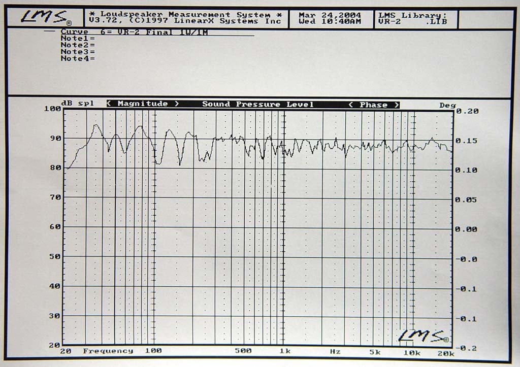
c. Kevin sent you a response measurement taken in our highly damped measurement/design room. That graph shows the entire response with an MLS measurement taken at one meter; this graph shows the typical dips and peaks caused by reflections from the boundaries. We include this graph to show the overall room response, which is quite flat!
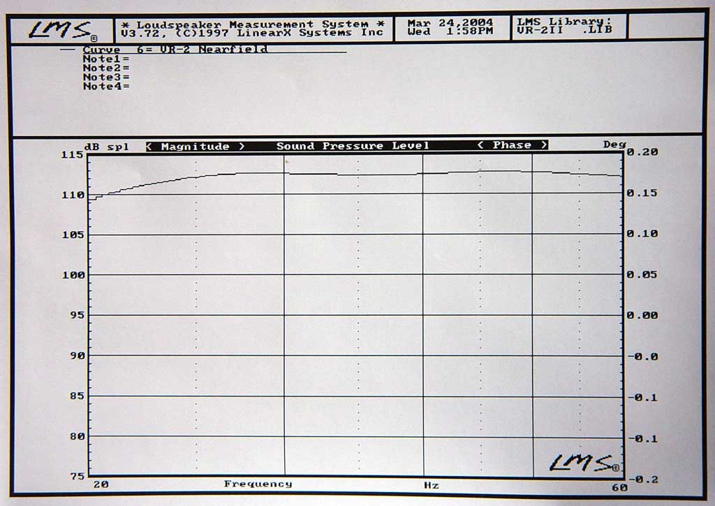
The second graph is a nearfield response taken without the room reflections, i.e. it is anechoic. Note that this clearly shows the VR-2 going down to the 25 Hz response
|
VR 2 Near Field Measurements in Design Room |
VR 2 Near Field Measurements without room reflections |
(Click Picture to Enlarge)
Real Time Analysis (RTA) from the Sencore SP295C Audio Analyzer ( updated 4/12/04 )
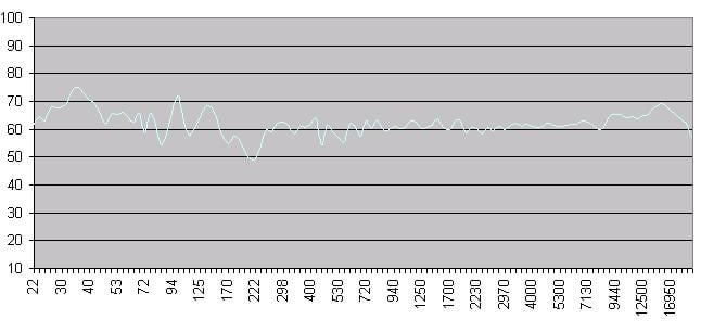
Figure 1. Quasi Nearfield (1 meter) 1/12 th Octave FFT Frequency Response
The overall frequency response of the VR-2 is uniformly flat and smooth with perhaps a slight emphasis in the highs. However, some of the bumps and dips in this response graph may be partially attributed to room acoustics especially since the room treatment is most effective in the mid bass to upper midrange area where the response is extremely smooth and flat, but de-emphasized slightly due to absorption.
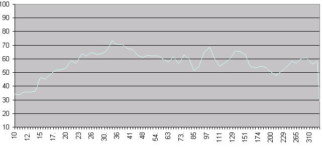
Figure 2. Quasi Nearfield (1 meter) 1/12 th Octave Low FFT Frequency Response
The VR-2's exhibited impressive bass response. However, since they seemed to be a bit energenic in the lower bass region (27Hz - 40Hz), I recommend placing them a few feet away from side and back walls to avoid excessive boundary gain. It appears the VR-2's had no problem reaching down to 25Hz and then some.
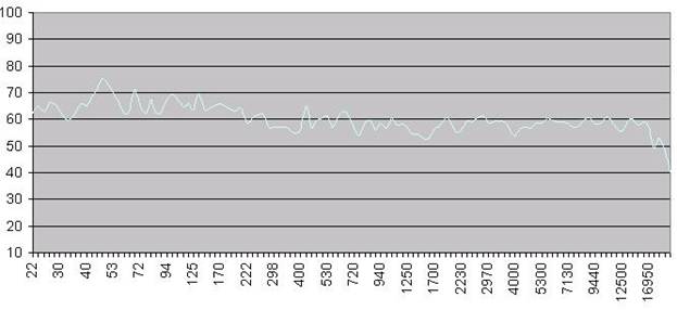
Figure 3. Listening Position 1/12 th Octave FFT Frequency Response
The VR-2's appeared to integrate well within our sound room with impressive low frequency bass response, smooth midrange and upper frequencies. I initially positioned the speakers with no toe-in (as in this measurement), thinking the slightly elevated high frequencies would best be minimized. However, it was apparent that they rolled off very smoothly off axis. If a little more energy at the high frequencies is desired, I recommend slight toe-in.
VR-2 Audition with the VR-S/1 Subwoofer
 At this point I decided to hook up the VR-S/1
subwoofers to see what they could do. The VR-S/1 sub includes a 10-inch down firing driver placed in a
very small box which would be great for an apartment with limited space. Keeping in mind that I have a
fairly large sized theater room with several strategically placed DIY sound panels and very dense pile
carpet these subs were not really able to provide a wave big enough to fill the room. They just aren't
made for this kind of set up as they are more tailored for small rooms or apartments.
So for a
quick test I turned them on their side so that the drivers were firing out into the
room.
At this point I decided to hook up the VR-S/1
subwoofers to see what they could do. The VR-S/1 sub includes a 10-inch down firing driver placed in a
very small box which would be great for an apartment with limited space. Keeping in mind that I have a
fairly large sized theater room with several strategically placed DIY sound panels and very dense pile
carpet these subs were not really able to provide a wave big enough to fill the room. They just aren't
made for this kind of set up as they are more tailored for small rooms or apartments.
So for a
quick test I turned them on their side so that the drivers were firing out into the
room.
We learned later that Von Schweikert Audio actually designed the VR-S/1 subwoofer to be front-firing as well. It was actually provided with stick-on rubber feet which was placed on the front baffle. When placed on the front baffle the amplifier was positioned on the top. This position ensured that the heat sinks could still ventilate upwards, allowing for proper heat transfer. This was an option for those individuals who were looking to install the VR-S/1 subwoofers within entertainment center cabinets. But if one wants this type of performance outside of such cabinets and does not mind the cosmetics of this type of placement, it was possible.
For our setup, which was in a very large room with
thick carpet, aiming the woofer driver toward the listening area provided more bass response although
it wasn't quite as predominate as needed for such a large room.
I then put them on small speaker
stands to decouple the subwoofers from the carpet. This position proved to clean up the bass
tremendously while the two (one for each channel) then became better bass contributors in this
setup.
Supplemental Info from Mr. Albert Von Schweikert
Mr. Albert Von Schweikert was kind enough to offer us his insight to the VR-2 design which can be read in our addendum . In addition to his comments, this page also includes near field measurement frequency plots along with an impedance plot. Please feel free to read this page as it provides behind the scenes in Von Schweikert's design objectives. Also keep in mind that the information provided by Mr. Von Schweikert is just a very brief summary of this design, as he tells us he could go on for weeks. We did feel that his letter to us did offer some very useful insight to his design philosophies. Even if you find this page incomplete, it should still provide some very useful and interesting information.
Conclusion
For being an entry level design for Von Schweikert priced at $2,495 per pair, the VR-2s are a notable performing tower loudspeaker speaker. Based on their design they do require more than just the drop and play approach. In an effort to make these speakers more affordable, Von Schweikert Audio implemented design concepts that require a bit more time and patience on behalf of the owner but the results are well worth the effort.
It is extremely important to decouple these speakers from the floor as is the case with most loudspeakers. The difference is that Von Schweikert Audio provides an aluminum plinth and spikes in order to do this adequately, but it still requires mass loading to the plinth. Based on recommendations from Von Schweikert Audio, lead shot seems to be the best alternative, especially when considering sand. Installing 25-lbs of lead shot will provide sufficient mass loading thereby preventing possible vibrations while helping to adequately load it on the plinth. Spikes mounted to the bottom of the plinth then decouple the speakers from the floor. Based on our multiple auditions this procedure provided a notable improvement in performance.
However, the items listed are not the only preparations the owner should consider. It's also important to optimize speaker placement within the room. What is interesting is that Von Schweikert Audio provides a very useful service to their customers which is uncommon. Their customers provide their room dimensions, and Von Schweikert Audio provides plots which outline where the speakers of the entire Home Theater setup should be located for best performance.
We found that the VR-2s presented a detailed sound with a smooth response along with sufficient imaging, especially with the ambiance tweeter engaged. The bass was tight, crisp and forthcoming and quite a surprise for a speaker this size. The VR-2s would serve quite well in a small or medium sized room. In larger rooms, such as the theater room used in our audition, it may be necessary to add one or two subs to further enhance the bass, especially if you are a bass-head.
Even though I am accustomed to a very big open sound which is a personal preference that I designed my own speakers to meet, I found the VR-2s to be a worthy contender especially when considering the price range and the competition. For those who prefer a smooth sound with ample dynamics, and tight bass, the VR-2s are well suited.
Von Schweikert Audio offered a stylish, well constructed cabinet with extremely fine quality wood veneers which added to their esthetic value. When considering their beauty and performance, the VR-2s are worth auditioning especially if you are looking for a speaker that will satisfy the audiophile in you while passing the Wife Acceptance Factor .
The Score Card
The scoring below is based on each piece of equipment doing the duty it is designed for. The numbers are weighed heavily with respect to the individual cost of each unit, thus giving a rating roughly equal to:
Performance × Price Factor/Value = Rating
Audioholics.com note: The ratings indicated below are based on subjective listening and objective testing of the product in question. The rating scale is based on performance/value ratio. If you notice better performing products in future reviews that have lower numbers in certain areas, be aware that the value factor is most likely the culprit. Other Audioholics reviewers may rate products solely based on performance, and each reviewer has his/her own system for ratings.
Audioholics Rating Scale
 — Excellent
- — Very Good
- — Good
- — Fair
- — Poor
| Metric | Rating |
|---|---|
| Build Quality | |
| Appearance | |
| Treble Extension | |
| Treble Smoothness | |
| Midrange Accuracy | |
| Bass Extension | |
| Bass Accuracy | |
| Imaging | |
| Dynamic Range | |
| Performance | |
| Value |
Ken Stein is a contributing writer and reviewer for Audioholics and he really REALLY likes his speakers (which he should, since he spent countless hours hand-crafting them himself.) Ken is an engineer with FedEx and applies his diligent attention to detail to his speaker and electronics reviews here at Audioholics.
View full profile