
Yamaha RX-V4600 Receiver Review
Yamaha RX-V4600 Receiver
- Product Name: RX-V4600
- Manufacturer: Yamaha
- Performance Rating:


- Value Rating:
- Review Date: July 22, 2005 19:00
- MSRP: $ 1899
|
|
Pros
- Three (3) HDTV-compatible component video inputs
- Accurate YPAO automatic speaker setup
- Presence channels & Yamaha DSP
- System memory with 6 storage options (2 on remote)
- Dialogue lift with Presence channels
- Independent volume trim for each input!
- Excellent fidelity in all modes of operation
- HDMI 1.1 Video and multi-channel audio
- Active i.LINK
- HD Radio
Cons
- Auto Setup had inconsistent results for PEQ and bass management
- No YPAO below 62.5Hz or on the subwoofer
- Remote button labels limit usefulness of backlight
- No analog video upconversion to HDMI
- Cannot engage Presence channels and Surround back channels even with the addition of an external amplifier
Yamaha RX-V4600 Introduction
It's been some time since a Yamaha receiver has graced my reference system. I still reminisce about the days of the DSP-A1, RX-Z1 and RX-Z9. Those were all class-leading products of their time providing some of the best fidelity and flexibility for home theater. But as of late, it seems the competition is fiercer than even. With other leading receiver manufacturers such as Denon, Marantz and Pioneer Elite bulldozing the competition with a line of products featuring all of the latest and greatest connectivity options, supportive formats, automatic setup & room correction, THX certification and processing, etc, it was only a matter of time before someone would shake up the status quo and offer these features in a product in the sub $2000 category. Enter the new Yamaha RX-V4600 - the 'does-everything-and-more' receiver at a price point that won't force users to refinancing their homes.
Yamaha RX-V4600 Overview
With our recent reviews of the RX-V2400 and its successor, the RX-V2500 , one wonders why we would review the new RX-V4600 which appears to be so similar, but at a slightly higher price? Truth be told there are distinct differences which we found to be invaluable for the additional $800 over the $1100 RX-V2500, such as:
- HDMI video switching (Ver 1.1)
- Active i.LINK
- HD Radio
- More robust amplifier section (see measurements and analysis section)
- Dedicated multi-zone remote control
- THX Select2 certification and processing
For those wondering about THX Select2 (the newest certification from THX) we have compiled a table illustrating its similarities and differences with the ultimate Ultra2 certification.
A Quick Comparison Between THX Select2 and Ultra2
|
Select2 |
Ultra2 |
|
|
Power Amplifier Comparison between THX Select2 and Ultra2
|
|
Select2 |
Ultra2 |
|
*Channel Loading |
4-ohm front
|
3.2 ohm |
|
Continuous testing |
Single channel only |
1,4 or 5 channels simultaneously |
|
Burst testing |
All channels (higher impedance lower voltage) |
5 channels |
|
Peak current |
12.5A front 6.2A surround |
18A peak |
*As you can see in our amplifier output impedance measurements, this requirement may be partly responsible for the RX-V4600's improved ability over the RX-V2500 for driving 4-ohm loads.
Yamaha RX-V4600 Setup, Configuration and YPAO
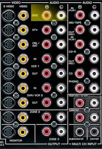
With all of the major I/O connectors on board, the RX-V4600 is as ready for the future as humanly possible at this price point. Two HDMI inputs, one output, dual active i.LINK, and EXT multi-channel analog inputs ensures all of the major formats are compatible with the RX-V4600. In the event of the emergence of newer surround formats such as DD+, the RX-V4600 sports an 8-channel external analog input. The receiver back panel was a bit crammed, but well arranged nonetheless with all of the digital audio and video connections on the far left, followed by analogue connections, then the speaker level connections, trigger connections and lastly the power cord and AC level connections.
Editorial Note About the External Analog Inputs on the RX-V4600
In order to utilize the 8CH inputs you must route the front outputs of your 8CH source into the DVD Inputs, and the Surround Back Outputs of your 8CH source into the Front/SB EXT Inputs. Then properly configure the Multi CH assignments in the GUI of the RX-V4600 for "8CH". Otherwise use the standard 6CH EXT analog inputs labeled on the back of the RX-V4600 for DVD-A/SACD, assuming your universal player doesn't have an active i.LINK / IEEE 1394 interface connection.For more information about this interface, see our Yamaha RX-Z9 review.
Editorial Note about the Impedance Selector Switch
I recommend the "Minimum 8-ohms" setting even for 4-ohm speakers of moderate efficiency ( > 89dB SPL). Yamaha includes a" 6-ohm" setting to satisfy UL heat dissipation requirements when driving 4-ohm loads, as well as easing consumer concerns about driving low impedance loads. These switches step down voltage feed to the power sections which can limit dynamics and overall fidelity. My advice is to keep the switch set to "Minimum 8-ohms" regardless of the impedance of your speakers and ensure proper ventilation of the Receiver. To illustrate this point further, I have tabulated my measured differences between the 8-ohm and 6-ohm setting for driving 8-ohm and 4-ohm loads.8-ohm setting: 134wpc into an 8-ohm load @ 0.1% THD; 210wpc into a 4-ohm load @ 0.1% THD
6-ohm setting: 95wpc into an 8-ohm load @ 0.1% THD; 180wpc into a 4-ohm load @ 0.1% THD
Automatic Configuration
Just as most of the latest generation Yamaha receivers, the RX-V4600 features their YPAO system which automatically checks and/or configures:
- Wiring
- Distance
- Size
- Equalizing
- Level
YPAO Parametric Room EQ Settings
YPAO allows you to set equalizing to the following parameters intended to aid in correcting the system for both room anomalies and differences in loudspeaker frequency response. One thing I found odd was the wording of the EQ modes. Wording in the manual almost suggests that Yamaha's YPAO is focused on taming the anomalies associated with mismatched and non-flat speakers, rather than compensating for room deficiencies. This is largely semantics as 50% of what reaches the microphone is coming from the room. However in our desire to educate consumers, it's always important to maintain the perspective that EQ is attempting to compensate for the loudspeaker to room interaction and not solely to attempt to linearize the loudspeakers' response. The available modes are:
-
Check: Natural
This mode averages out the frequency response of all speakers so that higher frequencies are less emphasized. This setting is only recommended if the Flat setting (or EQ off) seems too subjectively bright for your tastes.
Evaluation Summary: This mode seemed to provide a warmer sound quality to my system, with more emphasis in the lower bass region, but at the expense of sounding a bit bass heavy and compromising vocal intelligibility.
-
Check: Flat
This mode is supposed to average the frequency response of all the speakers and is recommended to be used if all of the speakers within your system are of equal quality.Evaluation Summary: This EQ mode seemed to provide a more aggressive sound quality in my system, depending on source material, sounding a bit forward and sibilant in the highs.
-
Check: Front
If your main speakers are of significantly better quality than the rest of the system this setting will attempt to adjust the frequency response of the other speakers to more closely blend in with the front channels.Evaluation Summary: This mode preserved the front soundstage but seemed to make the center channel sound a bit nasally or congested.
I didn't particularly care for the system response I was hearing with any EQ mode and was a bit disappointed in how little YPAO has evolved since its inception in the RX-Z9 . While PEQ seemed to evoke a more intimate listening experience, it made the sound seem more forced and unnatural. The Natural response seemed to muddy up the mid-bass while the Flat setting seemed to sound overly bright with too much bass boost which caused some source material to overload the woofers in my satellite speakers since YPAO incorrectly identified them as large and didn't apply bass management to them.
Recommendations on Auto Set-Up
Depending on your room characteristics, linearity of your speakers and listening preferences, you may have different preferences than what I noted here. Ultimately, I felt that no PEQ worked best in my setup since every EQ mode seemed to compress the soundstage or compromise the very open nature that my reference loudspeakers exhibit. As with any auto EQ, I recommend experimenting to determine what works best for your situation.
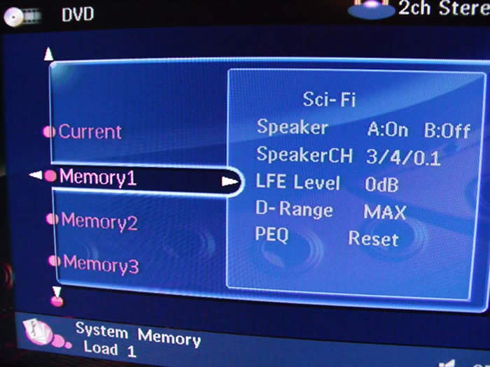
What really took me by surprise was the difficulty of defeating the PEQ. With prior YPAO Yamaha products it was a relatively easy matter of toggling between PEQ, GEQ or no EQ. In contrast with the RX-V4600 you had to enter each particular channel's audio setup and select "reset" to disengage the PEQ settings making it virtually impossible to do an A-B comparison and even more difficult for audiophytes to determine if it is even enabled or not. I even tried to engage the "Straight" mode to see if that would disable PEQ, but unfortunately t did not. In the end I did find a decent work around. By using the System Memory Settings feature (up to 6 storable allocations) of the RX-V4600, you can store independent Sound field program parameters, PEQ, Dynamic Range, LFE and speaker configuration settings. At this point it was a matter of toggling between Memory settings (#1 and #2 accessible on the remote) to do on-the-fly comparisons, though I would have preferred a single button toggle on the remote without the need to engage different memory banks.
 Comparing the auto level trim settings via the internal test tones, I found channel to
channel balance to be matched within +-0.5dB, while speaker distances were pretty much dead on or
closer than I could have gotten with a tape measure.
But double check the subwoofer distance is
accurate within a few feet as I have often found auto systems tend to incorrectly set the distance,
especially if the sub is placed in close proximity to the listening position.
YPAO was no
exception and set my subwoofer distance to 22ft when it was actually only about 12ft away.
Speaker sizes and crossover settings varied each time I ran the auto setup, thus I recommend taking
your results with a grain of salt.
Know your speakers and determine if the size and crossover
settings are appropriate or not.
If you aren't sure, consult your dealer and/ or loudspeaker
manufacturer.
At the very minimum, I would suggest using the auto setup feature for speaker level
and distances since for the most part, they are at best relatively accurate and a good starting point
for tweaking more accurate system performance.
If you decide on using PEQ, Yamaha provides user
flexibility to contour its response to your liking (a new feature not found on previous generation YPAO
enabled receivers).
Comparing the auto level trim settings via the internal test tones, I found channel to
channel balance to be matched within +-0.5dB, while speaker distances were pretty much dead on or
closer than I could have gotten with a tape measure.
But double check the subwoofer distance is
accurate within a few feet as I have often found auto systems tend to incorrectly set the distance,
especially if the sub is placed in close proximity to the listening position.
YPAO was no
exception and set my subwoofer distance to 22ft when it was actually only about 12ft away.
Speaker sizes and crossover settings varied each time I ran the auto setup, thus I recommend taking
your results with a grain of salt.
Know your speakers and determine if the size and crossover
settings are appropriate or not.
If you aren't sure, consult your dealer and/ or loudspeaker
manufacturer.
At the very minimum, I would suggest using the auto setup feature for speaker level
and distances since for the most part, they are at best relatively accurate and a good starting point
for tweaking more accurate system performance.
If you decide on using PEQ, Yamaha provides user
flexibility to contour its response to your liking (a new feature not found on previous generation YPAO
enabled receivers).
Editorial Note on YPAO
It's important to note that the YPAO system does not perform any corrections to frequencies below 62.5Hz, and does no correction whatsoever to the subwoofer channel meaning that it really cannot correct for many bass peaks caused by room modes. The best methods of dealing with room modes are: speaker/subwoofer location, listener location, adjustable PEQ. For more speaker calibration tips, please check out our System Set-Up and Configuration Tips.
Yamaha RX-V4600 HD Radio and Remote Controls
Listening to HD Radio on the RX-V4600
Radio seems to be the lost format in the home theater and music realm these days. Only a decade or so ago, tuner fanatics used to tweak and mod their AM/FM tuners for higher performance (see Yamaha T-80 Vintage Tuner Review ). With tuner performance becoming less of a priority in preamps and receivers these days, this further caused a loss of focus on FM radio being taken seriously as a high quality source. Luckily the digital era we embraced seems to have addressed this. Enter HD Radio from Ibiquity Digital Corporation.
Some of the Key Benefits Touted About HD Radio technology include:
-
Enhanced sound quality and reception over standard FM radio.
- Application services offering new features and information.
- Easy upgrade path to convert from analog to digital radio without service disruption using existing radio channels and bandwidth.
- Elimination of static noise and fading associated with conventional analog broadcasts due to multipath, noise and interference.
- Allowing radio broadcasters to send audio and data content via digital signals on the existing AM/FM bands.
- No subscription fee.
The last bullet certainly strikes points with me. At last - a high resolution broadcast format free to the general public. To get started, I advise checking out Ibiquity's website to locate HD Radio-capable channels in your area. I selected Florida, my home state, and got this list:
|
Station |
Band |
Frequency |
Format |
|
WBVM |
FM |
90.5 MHz |
Christian Contemporary |
|
WPOI |
FM |
101.1 MHz |
80's Hits |
|
WSUN |
FM |
97.1 MHz |
Alternative |
|
WWRM |
FM |
94.9 MHz |
Soft AC |
|
WFLA |
AM |
970 kHz |
News/Talk/Sport |
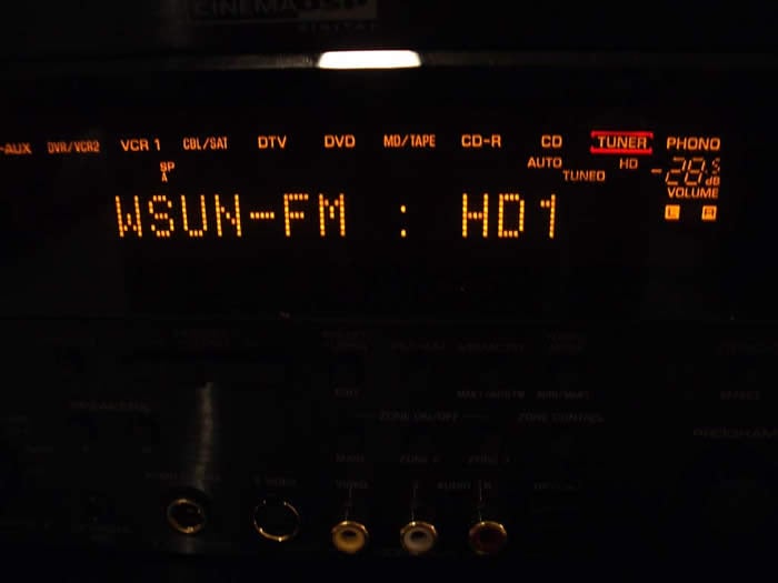 Using nothing more than the dental
floss monopole FM antenna wire supplied with the RX-V4600, I began tuning in stations.
The
strongest station in this list was 97.1MHz which, from my home, could be picked up on a decent tuner
without the use of an antenna (or a teenager's braces when they open their mouths.)
Within a
second or so, the RX-V4600 locked onto the 97.1MHz HD Radio signal.
My initial impressions were
that I must have been listening to one of the music channels on my satellite receiver, because I was
hearing no static or noise associated with AM/FM broadcasts.
It wasn't until I heard the DJ and
annoying commercials that my brain convinced my ears I was listening to a local radio station, though
with CD-like fidelity.
The HD Radio signal sounded much clearer and more detailed than standard
FM making radio almost bearable.
The AM HD Radio station was a bit too weak for me to lock onto
which was a shame since I would have loved to listen to my favorite talk radio - the
Phil Hendrie Show
noise free.
I am not a big fan of radio,
but if bubble gum pop or two-chord so-called "alternative rock" is your game, than you will certainly
dig listening to it using this system. Best of all, it won't cost you anything other than purchasing a
good antenna, though the Yamaha supplied ones may do you just fine.
Using nothing more than the dental
floss monopole FM antenna wire supplied with the RX-V4600, I began tuning in stations.
The
strongest station in this list was 97.1MHz which, from my home, could be picked up on a decent tuner
without the use of an antenna (or a teenager's braces when they open their mouths.)
Within a
second or so, the RX-V4600 locked onto the 97.1MHz HD Radio signal.
My initial impressions were
that I must have been listening to one of the music channels on my satellite receiver, because I was
hearing no static or noise associated with AM/FM broadcasts.
It wasn't until I heard the DJ and
annoying commercials that my brain convinced my ears I was listening to a local radio station, though
with CD-like fidelity.
The HD Radio signal sounded much clearer and more detailed than standard
FM making radio almost bearable.
The AM HD Radio station was a bit too weak for me to lock onto
which was a shame since I would have loved to listen to my favorite talk radio - the
Phil Hendrie Show
noise free.
I am not a big fan of radio,
but if bubble gum pop or two-chord so-called "alternative rock" is your game, than you will certainly
dig listening to it using this system. Best of all, it won't cost you anything other than purchasing a
good antenna, though the Yamaha supplied ones may do you just fine.
 Multi-Zone / Multi-Source Audio
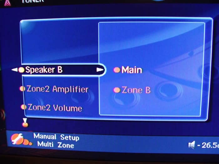
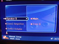
As with most receivers in this price class, the RX-V4600 features Zone2 and Zone3 multi source audio with the option of Zone2 being amplified by the Surround Back / Presence channels. In fact, if you are running a full fledged 7.1 speaker arrangement in the main room, make sure you pick up a 2CH amp and set the Zone2 amp is to "EXT" otherwise the back channels will not function. Zone2 and Zone3 will only allow analogue audio connections, so don't forget to run analogue interconnects for the source components connected to these zones. If you need an additional zone of audio, you can also configure SPK B for "Zone B", turn off SPK A and turn on SPK B. This will automatically disable the sub and surround speakers allowing you to use the Main preamp zone with digital audio inputs for another speaker location.
Video Set-Up
Alas, finally a Yamaha receiver with HDMI I/O connections (a feature lacking even on their flagship RX-Z9 ). The RX-V4600 is compliant to HDMI ver 1.1 which covers video up to 1080i and all audio formats except SACD (with SACD's almost universally-slow adoption rates we're starting to think that's less and less of a big deal.) I opted to use i.LINK for audio and HDMI for video for most of my testing of this receiver.
Editorial Notes about HDMI (especially for computer folks)
For more information on HDMI, we recommend our articles on HDMI and our Audio & Video Connections Guide.
You cannot connect display devices (such as presentation displays) that are NOT HDCP compliant. The result if you attempt this will be no picture. The RX-V4600 currently does not support analog video upconversion to HDMI, however it does support component video upconversion so it's a good idea to use this feature when handling composite, s-video and component video connections.
Yamaha RAV354 Universal Remote & RAV18 Zone Remote
The RAV remote controls are easy to operate, and have powerful feature sets. Now all we have to do is get Yamaha to fully backlight the RAV354 and we can retire the clapper.
Pros
- Very easily programmed
- Fits nicely in the hand, new thinner design
- Dedicated receiver volume
- Source switch for controlling inactive components
- Powerful Macro Features
Cons
- Seafoam button labels unreadable in dark, even with backlight
- Backlight barely lights up keypad
- Keypad does not adhere to standard layout
The Yamaha RAV354 Universal Remote Control
The RAV354 fits easily in the hand so that most commonly used keys are positioned within easy reach of the thumb. This includes volume, channels, menu, navigational and the enter button. Even DSP functions are within easy reach without having to maneuver the remote control, though when using to the receiver in a dark room you better make sure you have the control selector set to "amp" otherwise you will wind up changing the channel rather than the DSP mode. The fact that all keys are now backlit (activated via a button on the left side of the remote) would be cause for small celebration except that the remote stopped just short of the first down and opted to include "sea foam" colored labels on many of the primary buttons - rendering them nearly invisible in the dark, even when backlit. One other thing to note is that the numeric keys (which are not arranged in the familiar 4 rows of 3 format) are also poorly and unevenly backlit. I suppose I am spoiled with my Universal MX800 remote, but I feel that all of the buttons should light up when you engage the backlighting even at the expense of battery life, which today is less of an issue with rechargeables being commonplace.
Programming the remote is about as easy as it gets, short of using mental telepathy. The only difficulty I had, which was remedied with a paper clip, was accessing the programming buttons. This is understandable since you don't necessarily want these buttons to be easily accessible to the spouse or kids. I also liked the feel of the buttons themselves. The no-slip texture is easy on the hands and helps ensure you select the right buttons. Users of previous Yamaha remotes will need to get used to flipping the new AMP/SOURCE/TV switch which is a nice development that instantly directs remote control commands between the receiver, currently selected source, or television (as programmed into the DTV source.)
Separate power buttons for the receiver, source and television help ensure that you'll never mistakenly turn off the wrong device. I also appreciate the "Audio Select" button, which was incidentally backlit and allows the user to toggle between formats of a particular source (i.e. Auto, PCM, Analog). The numeral 7 "Select" button allows the user to toggle between different surround modes (i.e. PLIIx Music, Movie, DTS Neo:6, CSII, etc), a feature I most commonly utilized, really begged to be backlight. I am hopeful Yamaha reconsiders this for future iterations of this fine remote. Until then, my clapper remains plugged into the lamp in my listening room.
The RAV18 Zone Remote Control
The sole purpose of this remote is to operate the Zone2 and Zone3 sections of the RX-V4600. I really liked having a separate remote for these features as it helped eliminate an inexperienced user messing up your system's primary settings while trying to make the outdoor speakers louder at a pool party. This is the remote (if any) you let your guests use. It isn't backlit, but considering people using the Zone2 and Zone3 features likely never do so in the dark, I don't see this as being an issue.
Yamaha RX-V4600 Listening Tests
All the features aside, it all boils down to sound quality in the end. For without it, we would all be happy with our clock radios or cube speaker systems.
Two-Channel CD / SACD

First up was my usual listening sessions with my trusted Patricia Barber SACD's Café Blue and Modern Cool. With i.LINK engaged between the RX-V4600 and my Denon DVD-5900 it was smooth sailing. I enjoyed her melodic overtures and the bands instrumentals with full bass management. I didn't detect any noise issues like I did on the Integra Research RDC-7.1 , nor did any distracting artifacts present themselves. Kicking off my shoes and opening a nice Belgium Lambic I popped in some Michael Franks Burchfield Nines which quickly evaporated my worries of daily life activities. The RX-V4600 had no qualms driving my reference speakers and did especially well at low listening levels indicating very good Signal to Noise (SNR) system performance.
I also tried two-channel sources in Circle Surround (CS) II Music Mode and found my results to vary depending on source material. In best case scenarios it added vocal clarity and expansiveness to two-channel sources. On the flip side, it either added no discernable improvement or a slight loss in stereo separation. CSII is certainly a value added tool in setups having only a primary pair of speakers for stereo. However, in the end I either listened to two-channel music sources in "Source Direct" or in PLIIx Music Mode. Had I only been using the RX-V4600 with two speakers, I would have likely taken more advantage of this processing feature.
Multi-channel Audio
A couple of months ago, I had the distinct honor of interviewing one of my all time progressive rock bands - Marillion. During our interview of the band , we learned many insightful things such as the history of their music, the inside stories surrounding the meaning of the lyrics and much more. You could imagine I was tickled pink to get a signed copy of their latest concert tour titled Marbles on the Road.
I switched off the Surround Back channels in favor of the Presence channels knowing I would want to take advantage of Yamaha's Cinema DSP modes, which in my opinion truly shine for concert videos and DVDs. I toggled between The Roxy Theatre and The Bottom Line music DSP modes but settled on the latter after toning down some of its adjustable parameters. It provided the most spacious sound field without sounding artificial or overbearing.
The first track "The Invisible Man" is a strong opening for this DVD. It really demonstrates the versatility of the band's music and the power of Steve H's vocals. With Cinema DSP engaged, it brought me closer to the "live" experience providing a very expansive and reverberant surround field while still maintaining a great deal of vocal intelligibility and focus. Listening to the live rendition of " Bridge", the title track from the album Brave, was truly an awesome experience. The enveloping surround effect, of course the passion in Steve H's voice, prompted me to pop in the Brave CD after he finished this performance. I found myself halfway into this CD before I realized it was nearly 2am! I actually preferred listening to the studio CD of Brave in PLIIx Music Mode. As with prior Yamaha receivers, I have found their music DSP modes to work best with live reverberant program material such as concert videos, but for normal music, I usually prefer either stereo or PLIIx Music Mode. In any event, Cinema DSP is a good tool to have in your audio bag of tricks which can enhance your listening experience with the right source material. For all other scenarios, Yamaha sports the standard surround processing or plain vanilla stereo bypass.
Home Theater
I know The Fifth Element isn't exactly a "current" title, but come on, this movie is a classic. It's funny, surprising, loaded with cool visual effects and action and best of all it has Milla Jovovich. Adventure Mode overlaid with PLIIx Movie was most enjoyable. Though, I wished Yamaha would have provided an independent preamp output for the Presence channels so I could have engaged a full 7.1 + 2 speaker configuration with an additional two-channel amp. Engaging the Presence channels really makes Cinema DSP modes shine. As with their previous 7.1 receivers (i.e. RX-V2400/2500) Yamaha missed the boat on this. The only current Yamaha receiver that can engage 7.1 EX with the additional two Presence channels is their $4,500 super receiver - The RX-Z9.
Space battles from The Fifth Element and flight scenes from The Aviator sounded spectacular on the RX-V4600. Channel to channel separation was excellent, panning fluid, and surround field envelopment a hallmark of Yamaha since the days of their first Dolby Digital-enabled receivers. Power and dynamics were never an issue in my listening experiences, especially since I had all reasonably efficient speakers ( > 89dB SPL @ 1meter) crossed over at 80Hz with the very potent Axiom Audio EP500 subwoofer handling all of the starship and airplane explosions.
Whether I listened to straight DDEX, PLIIx or Cinema DSP, the RX-V4600 provided a 'better than movie theater' surround experience allowing me to enjoy my favorite movies in the comfort of my home theater room and absence of a crowed and sticky cinemaplex with overpriced and over-salted popcorn.
Suggestions for Improvement
As good as the Yamaha RX-V4600 is, there is definitely margin for improvement which we would like to see in future model iterations such as:
-
Single button toggle ability to engage/disengage PEQ
-
More accurate and consistent auto speaker size and crossover configuration
- Subwoofer PEQ or an adjustable notch filter with variable gain and Q.
- Analog video upconversion to HDMI with OSD Display
- Easier accessibility of channel trim adjustments via the remote
- Fully-backlit remote control with standard keypad layout
Yamaha RX-V4600 Power Measurements and Analysis
Preamplifier Tests
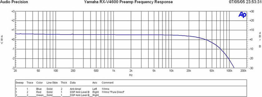
Frequency Response
The frequency response out of the preamp
was ruler flat in the audio band (20Hz to 20kHz +-0.1dB) with a -3dB point around 120kHz.
I also
observed no measurable difference between "Straight" and "Pure Direct".
FFT Distortion Analysis
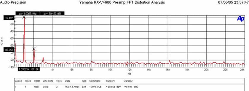
When the analog preamp was driven at 1Vrms (typically ½ signal strength to achieve ½ of max power of most power amps with voltage gain of 29dB) distortion levels were (+0.497 + 88.955 = 89.452dBv) or 100*alog(-89.452/20) = .00337% This is certainly a commendably low distortion figure.
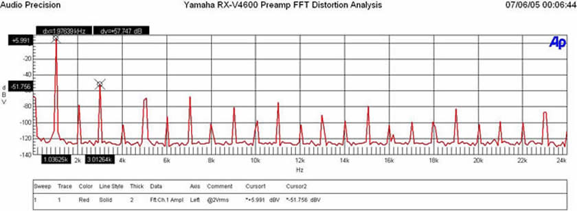
At 2Vrms, the preamp section of the RX-V4600 faltered. This is because Yamaha was likely using only a single rail 5V supply for the preamp section. I would prefer to see a preamp have the ability of driving 2Vrms undistorted to accommodate a wider assortment of power amplifiers. Though this didn't present any audible nasties when I used the RX-V4600 as a preamp to my Emotiva MPS-1 power amp, my advice here is to choose a power amp that can achieve maximum power output with about a 1.5Vrms input should you decide on buttressing your system with external amplification.
Signal to Noise Ratio
- The Inputs can handle 3Vrms unclipped!
- Outputs Deliver nearly 2Vrms output unclipped! But FFT distortion becomes very high once output exceeds 1.5Vrms.
Ch-A Signal to Noise Ratio (SNR)
-
-106.85 dB below 4.23 dBV Reference Level (at 0.10 % THD+N)
-
< 10 Hz - 22k Hz bandwidth , no option filter and no weighting
With a 200mV Input Signal, I adjusted master volume for 1Vrms out, preamp gain (Av=5 or 14dB), I measured as follows:
- 18.5dBrA with signal
- -74.6dBrA without signal
- SNR: 93dBrA (commendable performance for a preamp at any price class)
RX-V4600 Power Amplifier Tests
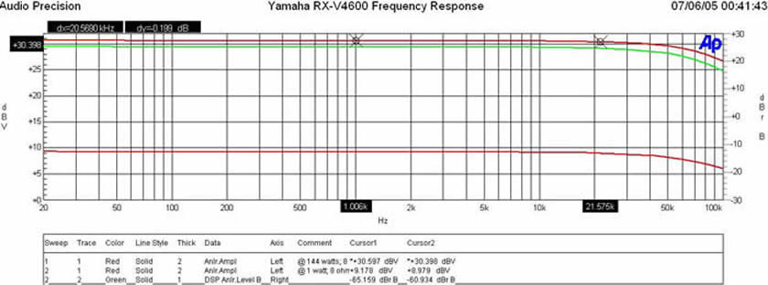
Frequency response uniformity over all power levels was excellent (within +-0.1dB from 20Hz to 20kHz).
RX-V4600 Distortion Tests
|
of Channels |
8-ohms
|
8-ohms
|
4-ohms
|
4-ohms
|
|
RX-V4600 1 CH |
134 wpc |
144 wpc |
210 wpc |
225 wpc |
|
RX-V4600 2 CH |
116 wpc |
128 wpc |
175 wpc |
184 wpc |
|
RX-V2500 1 CH* |
NA |
146 wpc |
NA |
199 wpc |
|
RX-V2500 2 CH* |
NA |
135 wpc |
NA |
119 wpc |
*Line voltage was lower during testing of the RX-V4600 which accounts for the negligible edge to the RX-V2500 in 8-ohms. We did not test the RX-V2500 at 0.1% distortion so those measurements are unavailable.
Upon first inspection it would appear the RX-V4600 delivered similar power measurements to the RX-V2500 (see measurements and analysis ), until you take a closer look at the RX-V2500 power into 4-ohm loads. In the case where 2CH are driven into 4-ohms, the RX-V4600 delivered 184wpc @ 1% THD (onset of clipping) while the RX-V2500 delivered about 119wpc under the similar testing conditions. What's most impressive is the RX-V4600's apparent better handling of low impedance loads when compared to the lower priced RX-V2500 as can be seen in our output impedance and damping factor measurements.
RX-V4600 Signal to Noise Ratio Tests
With 200mV in and 2.82Vout into an 8-ohm load,
- < 10 Hz - 22k Hz bandwidth , no option filter and no weighting
Measured at 1 watt: 200mV input: Master Volume: -3.5dB
- At 1 watt: -21.69 dBrA
- At idle: -103.46 dBrA
- SNR: 81.7dB at 1 watt This is very good performance
Yamaha RX-V4600 Power Measurements and Analysis - Part 2
Amplifier Output Impedance and Damping Factor Measurements
Test Notes:
- All amplifier power references were conducted under load and compared to open circuit voltages to determine output impedance as per our Basic Amplifier Measurement Techniques Guidelines.
- All max power tests represent 0.1% THD at 1kHz as a reference
- Distortion at 20Hz and 20kHz was also checked to ensure THD was always under 1%
- Line Voltage was monitored to ensure no sag was present (115Vrms recorded)
- Reference 1 watt = 2.82Vrms into an 8ohm load
The output impedance of the RX-V4600 was commendably low for a single pair transistor push-pull amplifier stage. It also appeared to be more uniform than what we have seen in the RX-V2500 indicating that the series output inductor after the last output stage to increase stability may have been eliminated or its value reduced.
Damping factor remained stable and uniform at into an 8-ohm and 4-ohm load. Based on the principle of voltage divider, we see roughly a little less than ½ the damping factor for the 4-ohm load. Ideally it would have been exactly ½, but this is certainly better performance than we have seen with the RX-V2500. The damping factor remained close to our minimum recommendation of 50. For more information on this topic, read our article on Damping Factor: Effects on System Response .
Amplifier output impedance and damping factor at full power (128wpc 8-ohms, 200wpc 4-ohms; respectively) remained highly linear. The RX-V4600 excelled on this test in comparison to the RX-V2500.
Yamaha RX-V4600 Conclusion
As with the tradition of all Yamaha A/V receivers I have had the pleasure of reviewing, the RX-V4600 lives up to the Yamaha name. Its feature packed, excellent processing capabilities stand out at this price point. Its improved amplifier performance over the RX-V2500 ( see test results ), particularly when driving low impedance loads, opens it up to a bigger loudspeaker market while also making it somewhat more predictable sounding when driving the tougher loads. While there were some items I would have liked to see improvements on, they certainly didn't take away from the quality, value and enjoyment of this product. Whether used as a dedicated pre/pro or a full-fledged receiver, the RX-V4600 will likely satisfy the needs of all but the most elaborate home theater installations. As with all prior Yamaha receivers I have reviewed, their forte is truly home theater, but this doesn't imply slouch performance for music. On the contrary, its arsenal of processing features to enhance music (ie. CSII, PLIIx, etc), i.LINK for high resolution formats such as DVD-A/SACD, and its improved amplifier performance makes it right at home for your music needs. It's always a difficult task to pack up a Yamaha receiver after my review is over and I almost always miss the Presence channels for use with cinematic and concert movies. The RX-V4600 is certainly no exception in this instance. Until then, I leave my extra speakers in place and an open theater chair for their next round.
6660 Orangethorpe Avenue
Buena Park, CA 90620
(714) 522-9105
Yamaha RX-V4600
MSRP: $1899
www.yamaha.com/yec
The Score Card
The scoring below is based on each piece of equipment doing the duty it is designed for. The numbers are weighed heavily with respect to the individual cost of each unit, thus giving a rating roughly equal to:
Performance × Price Factor/Value = Rating
Audioholics.com note: The ratings indicated below are based on subjective listening and objective testing of the product in question. The rating scale is based on performance/value ratio. If you notice better performing products in future reviews that have lower numbers in certain areas, be aware that the value factor is most likely the culprit. Other Audioholics reviewers may rate products solely based on performance, and each reviewer has his/her own system for ratings.
Audioholics Rating Scale
 — Excellent
- — Very Good
- — Good
- — Fair
- — Poor
| Metric | Rating |
|---|---|
| Frequency Response Linearity | |
| SNR | |
| Output Impedance | |
| Measured Power (8-ohms) | |
| Measured Power (4-ohms) | |
| Multi-channel Audio Performance | |
| Two-channel Audio Performance | |
| Video Processing | |
| Bass Management | |
| Build Quality | |
| Fit and Finish | |
| Ergonomics & Usability | |
| Ease of Setup | |
| Features | |
| Remote Control | |
| Performance | |
| Value |
Gene manages this organization, establishes relations with manufacturers and keeps Audioholics a well oiled machine. His goal is to educate about home theater and develop more standards in the industry to eliminate consumer confusion clouded by industry snake oil.
View full profile