
Denon AVR-5805 AV Receiver Review
Denon AVR-5805
- Product Name: AVR-5805 A/V Receiver
- Manufacturer: Denon
- Performance Rating:

- Value Rating:

- Review Date: May 15, 2005 19:00
- MSRP: $ 6000
|
|
Pros
- Phenomenal performance & fidelity
- Unprecedented Power Reserves
- (see measurements)
- Independent Multi Room Surround
- Excellent trigger options
- HDMI & IEEE 1394
- Awesome Audyssey room correction
- Upgradeable architecture
Cons
- BIG
- Complex
- No OSD for HDMI (available summer 05)
- No analog video up-conversion to HDMI (also available late summer '05)
Denon AVR-5805 Introduction
There are pivotal moments in our society where we make quantum leaps in progress. Whether it pertains to civil rights or technology innovations to improve our lifestyle isn't the point. As a people, we strive to be better than ourselves and this may be our one endearing quality as a species which differentiates us from other primates. Ironically, this same concept can also be applied to home theater, though on a much smaller and perhaps less significant scale in the grand scheme of life. It's not often that a manufacturer makes a product under the guise of a certain category that absolutely shatters its stereotype and redefines the category or elevates it beyond the status quo. Lately, this appears to be a more common occurrence than not with Denon Electronics. Enter the AVR-5805, a 10CH AV receiver masterpiece. Read on to find out why.
Denon AVR-5805: The Ultimate One Box Separates Solution
About a year and a half ago we reviewed Denon's flagship A/V receiver, the AVR-5803 . At the time this was one of the best receivers on the market, outgunning many dedicated pre/pros, not just because of its stunning performance, but because of its intelligent and complete bass management solution, host of innovative features - most of which were captured in our detailed review and A/V Processor Checklist (which this product was partly responsible for us revamping since it raised the bar on performance and feature expectations). In fact, the AVR-5805 managed to score 100% of our critical features and nearly all of the bonus features on our list, not to mention having a host of features not even listed in our checklist (time to update again)! See the Denon AVR-5805 Checklist Scorecard .
The major additions of the new AVR-5805 over its predecessor, the venerable AVR-5803, are almost too numerous to list but here are a few key ones that stand out:
|
|
Our First Look article offered a glimpse into what I refer to as a Multi Function A/V Control Center since it's so much more than what we normally think of when we hear the word "receiver". In this review we plan on going much deeper into the primary functions of this product for a dedicated multi-channel surround solution. In later articles, we will follow up on its multi-room, multi-source capabilities as well as upgrade functions when they are made available by Denon.
When I first got news on the concept of the AVR-5805 and its subsequent price tag I briefly pondered if Denon had finally gone off the deep end in home theater lunacy until I actually envisioned the purpose and endless possibilities of this product. The idea on having a one-box solution that could not only give separates a run for their money, but also distribute independent multi-channel audio into two unique zones while also distributing up to 22 channels of audio into an entire house became quite an ingenious concept in my mind. Throw in some other goodies such as the Audyssey room correction system, support for the latest audio and video formats and you have a unique product solution that would typically require 3-4 boxes from their competitors and still may not offer the entire gamut of features this single box solution possesses!
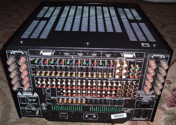
Denon AVR-5805 Back Panel - Got Cables?
Denon AVR-5805: Build Quality
Pretty much every current conceivable A/V connection (except for balanced and AES) is represented on the back panel of this baby. The speaker terminals are very high quality WBT binding posts that snugly fit even the most challenging banana plugs such as my 10AWG Cobalt Cables that slip off typical conventional plastic binding posts. Considering the complexity of this back panel, I found the arrangement to be well thought out and organized. I liked the fact that all of the toslink, coax, and HDMI connections were not assigned to any particular input. I found it useful to take note of what component I connected to each interface so I could later properly configure the settings in the OSD and eliminate the trial and error process of finding the right designations. Note the dual IEEE 1394 connections at the bottom center for digitally passing DVD-A and SACD from Universal DVD Players. Denon also provisions their own higher bandwidth D.Link ver 3 proprietary connection to function with their own Universal players (SACD transmission still pending approval). Also notice the Ethernet connection on the back. According to Denon, the Ethernet port upgrade later this summer will provide the ability to stream audio content from a PC with control and OSD by the AVR-5805 as well as Internet Radio access (no PC needed for this, only Broadband Internet access). Note, there is no access to the Internet or online service provided by Denon or the AVR-5805, it merely functions as a 'client'. Also coming is Web Browser functionality to permit off-site access to the AVR-5805 for diagnostics or updates.
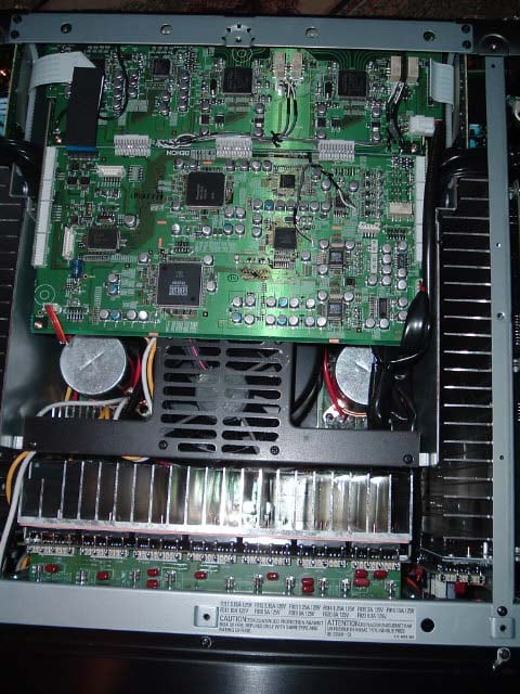
Inside view of the Denon AVR-5805 AV Receiver
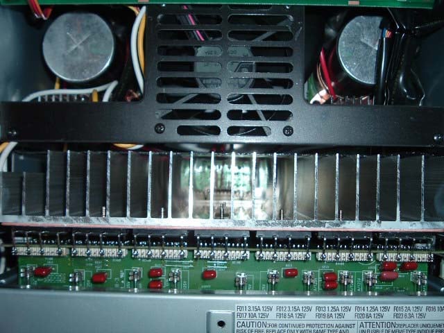
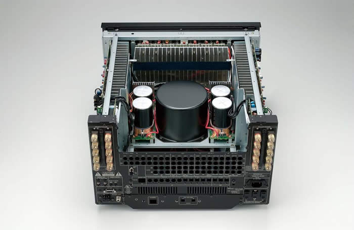 Inside the AVR-5805 is a marvel of technology including three of the latest 32 bit DSP chipsets from Texas Instruments (main zone) and one 32 bit analog SHARC borrowed from the AVR-2805 for Zone2. Top of the line Burr Brown DACs and ADCs, which by themselves cost more per chip than entire multi- channel DAC solutions from most costlier manufacturers of so called high end separates components. Silicon Image HD M I transceivers, Genesis I/P scaling and video processing are some of the other goodies found under the hood of this battleship. The power amps utilize robust power transistors in push pull configuration that, based on my measurements and listening tests, can go toe to toe with many dedicated multi-channel power amps in the $2-3k price range. There are plenty of heatsinks spread out across the front and side of the chassis to provide cooling. Two internal fans (which I only heard turn on briefly during my power torture tests) are mounted towards the center of the chassis and are used under extreme conditions to provide forced cooling, drawing heat away from critical components such as the transistors, chips and electrolytic capacitors. With over 10,000 components inside (more than 3 times that of the AVR-5803), this product certainly garners the respect of fellow engineers and the fear of service technicians.
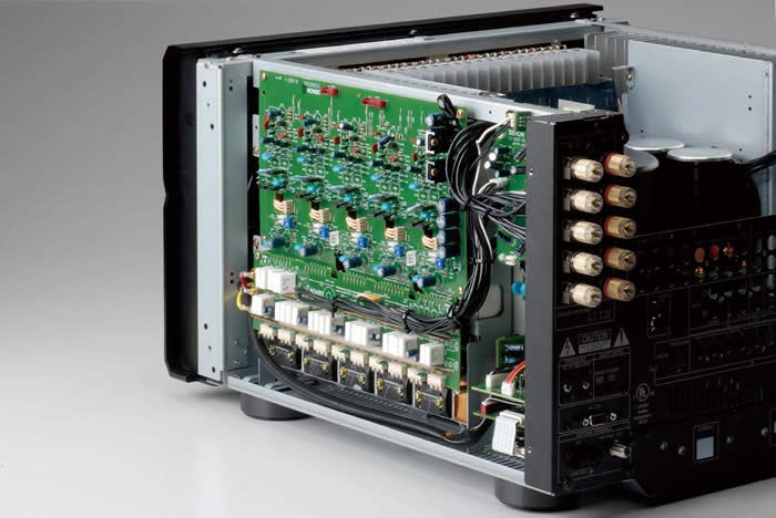
The layout follows the proud tradition of the 5800 series of Denon receivers. The power supplies are located dead center, actually two additional E-core transformers (borrowed from the AVR-2805) are located on the backside of the receiver to provide additional power capability for the 10 internal 170wpc amplifiers. The power supply capacitance is more than double that of the AVR-5803! The power supply in the AVR-5805 rivals all other flagship receivers to date. Whether you are driving 2 channels or 10, the AVR-5805 is certainly up to the task at utilizing all of the current from a 15A wall outlet, so make sure you run a dedicated line for this monster.
Editorial Note on the AVR-5805 Amplifier Design
- Two high current complementary output power BJTs per channel (with smaller cascaded devices) - paralleling multiple BJTs is a good method of ensuring amplifier output impedance is low enough to deliver high current while driving low impedance loads. It's also an effective way of minimizing frequency response variations which can occur when driving highly reactive speaker loads and exotic cabling. While the AVR-5805 doesn't have the real estate to sport multiple sets of power devices typically found on dedicated amps, it does have a single and conventionally much larger pair per channel that are top notch and as you can see in our measurements , perform commendably well.
- Multiple high voltage (80V) capacitors (4 x 33,000uF = 132,000uF, or 66,000uF per rail). In order to do 170wpc, a minimum recommended cap voltage of sqrt(2)*34.64 + 5 = 57V should be used. Using 80V gives them plenty of design margin and added headroom since the rails can swing much higher.
- A massive torodial transformer (borrowed from the AVR-5803) and dual E-core transformers (borrowed from the AVR-2805) ensures this amp can utilize the full rated power from the wall outlet (120V,15A) if called upon.
Denon AVR-5805: Set-Up and Configuration
 One of my biggest fears (other than physically moving this unit onto my shelf) was the overwhelming configuration possibilities that I thought would require a PhD to properly operate. Realizing the complexity of this receiver, Denon opened up a certification training class for their Custom Installers and were nice enough to invite me to one of the first classes. This course, about 8 hours in length, runs you through all of the configuration and setup options of this receiver. It first teaches you the difference between assigning and configuring the channels and power amplifiers and then guides you through the most important sections of configuration. Perhaps the most important lesson in this class was that many of the settings in each menu directly affect other settings. For example, assigning channel configurations will alter the options you have for power amp assignments. Another example f this shows up when assigning audio and video inputs. The AVR-5805 will set priority to HDMI configurations, so if you inadvertently configure your video options after assigning audio options for a particular input, it will default that input to HDMI for both audio and video. Because of this, my advice would be to configure all of your video options before setting up audio. In fact, listed below are my recommendations for configuring the AVR-5805 for the first time.
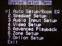 Recommended Initial Set-Up Configuration Procedure for the AVR-5805:
Step #1: Enter Menu Option 4: Video Setup and assign your video inputs and connectivity.
Step #2: Enter Menu Option 3: Audio Input Setup and assign your audio inputs and connectivity.
Step #3*: Enter Menu Option 7: Option Setup and configure your channel setup and power amp assignments, followed by Trigger options.
Step #4: Enter Menu Option 1: Auto Setup/Room EQ , connect the Denon supplied microphone and begin auto calibration following the prompts on screen.
Step #5: (optional) Enter Menu Option 2-2: Subwoofer Setup and configure Subwoofer Mode to "LFE+ Main " if you desire subwoofer output derived from Main channels set to "Large" as well as Menu Option 5: Advanced Playback to enable subwoofer output in 2CH mode.
* Alternatively you can configure channel and amplifier assignments in the Auto Setup menu from Step #4 before engaging the auto mic calibration.
After the auto calibration completes, you still have to enable your desired EQ response (if any). There are two ways to accomplish this: 1) via the OSD menu under the 1.2 screen, and the other via a hot key on the remote labeled "EQ". I prefer the former since you can toggle the Audyssey EQ on/off on the fly while listening to determine your preference as opposed to toggling though the gamut of EQ options. In menu option 1-2 Room EQ Setup you can assign what surround modes have the EQ applied. You can even enable the EQ for Pure Direct mode in option 1-3 Direct Mode Setup.
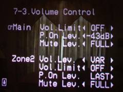
The channel configuration options seem endless and are certainly the most comprehensive in a single box solution to date. In my setup I chose 7.1 with dual subwoofers configured as Left and Right stereo pairs. This is ideal for stereo two-channel and is an excellent choice for home theater since the LFE and channel info from all other channels set to Small gets equally split into the two subwoofers. You can also configure the two subs for front/back and LFE/ Main. What is icing on the cake is the fact that the AVR-5805 offers independent channel level and distance compensation for all three of the subwoofer outputs! This is essential for properly integrating a multi subwoofer system short of making these adjustments via the subwoofer amplifiers (except for distance compensation). Zones 3 and 4 can be configured as stereo or mono and even employ an optional HPF set for 80Hz. Remarkably, the main zone can be shut off via the remote so users operating other zones can't fool with the settings. We will revisit Zone2 5.1CH in a future article when we exercise the AVR-5805's full multi function capabilities in a new home theater environment.
Editorial Note on Subwoofer(s) Configuration of the Denon AVR-5805
The AVR-5805 is the most versatile product on the market not only for bass management, but for subwoofer integration and configurability, particularly when dealing with multiple subs. It allows you to assign up to three subwoofers for the primary zone, designate channel assignments for each sub, and sports independent distance and level compensation and crossover frequencies. With this much sophistication comes careful planning and configuration by the end user or installer. Following these basic guidelines will help ensure your subwoofers are properly managed and configured:
- Identify how many subwoofers are in your system.
- Identify their location(s).
- Assign them the proper output composition as shown in the table matrix on page 99 of the user manual.
- i.e. for 2 sub systems your choices include L/R, F/B, LFE/ Main.
- *For 3 sub systems your choices include L/R/LFE (an option we will explore in a follow up article), F/B/LFE.
- *Note you cannot use 3 sub configurations if you plan on setting up a 5.1 system for Zone2.
- Identify your speaker configuration to determine subwoofer connection pre outs as per the connection tables on page 100 of the user manual. This is important as the subwoofer connection pre outs are different for 5.1, 7.1 and 9.1 speaker configurations.
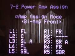 Next up is power amp assignment, touted by Denon as the industry's first fully assignable amp section. There are several standard configurations to choose from, including the pictured Bi-Amp Front mode which is what I used in my set-up, as well as a custom mode to let you assign exactly what channels get amplified. In order to Biamp prior Denon receivers such as the AVR-5803, it required a fairly comprehensive and methodical procedure to ensure proper level matching and assignability. Not anymore! Now all you have to do is select this function and the amp gains in Biamp mode are perfectly matched. I even checked them with an R M S meter and found each amplifier to be within 10mv (.008dB) of each other. Now that is excellent channel matching! I could have opted to biamp the center channel as well with the extra available amp but found little use for it and decided against it.
Just like with the AVR-5803, the AVR-5805 provisions for two types of surround speakers labeled SPK A and SPK B. The idea here is to allow the user switchability of the rear channels between direct radiators for music and dipole/bipole for movies. It even remembers the proper calibration for each and, if you prefer, you can have two sets of speakers running off of SPK A and SPK B simultaneously. Talk about having your cake and eating it too! To take it one step further, Denon also incorporated an independent trigger with assignability for each type of surround mode allowing the audiophile and home theater aficionado the option of altering driver configurations on hybrid speakers that accept triggers to take advantage of such functionality.
OSD of Denon AVR-5805
Denon AVR-5805: Audyssey and System Set Up
Before diving into the set-up of the new Audyssey MultEQ system, I thought it would be prudent to interview Audyssey regarding it operation and calibration to ensure I would maximize its potential in my system.
Interview with Chris Kyriakakis from Audyssey on MultEQ
Audioholics: How does the Audyssey system differentiate between first arrival and reflected sound?
Chris: MultEQ does not "differentiate". It uses long impulse response measurements that account for the combined effects of first arrival and reflected sound. The challenge in doing that is to create filters that are short enough in length to be practical for consumer applications. MultEQ uses novel signal processing methods that are based on psychoacoustics to reduce the filter length without sacrificing correction accuracy.
Audioholics: How is this system different than others on the market that typically use a variable PEQ?
Chris: There are two fundamental differences:
(i) MultEQ is not a parametric method that uses IIR filters for a number of bands. Instead it uses FIR filters. The advantage is that this allows both time and frequency domain correction, whereas IIR-based PEQ methods can only correct the magnitude response
(ii) MultEQ combines the measurements from several listening locations in the room. Furthermore, it does so not by averaging, but rather by a weighted combination of the responses that results in a much more precise representation of the room problems. Spatial averaging methods suffer from the fact that a peak at a certain frequency in one seat might be a dip at the same frequency in a nearby seat. Averaging will smooth the peak and dip into a response that is nearly flat and thus tell the filter to not perform correction at that frequency. M ultEQ clusters responses throughout the listening area using fuzzy logic rules. This method assigns "importance" weights to each response and combines them appropriately. As a result, peaks are moved down and dips are moved up for all locations.
Audioholics: What are the recommended room conditions to obtain accurate calibration results (i.e. NRC level, RT60 time, etc)?
Chris: MultEQ adapts to noise in the room by measuring it. The test signal is then repeated at a higher SPL level until the desired SNR is achieved to guarantee good response measurements. RT60 has been taken into account in the design of the Audyssey target curve.
Audioholics: What are the max/min boosts of the Audyssey system?
Chris: These are determined by careful consideration of the gain structure in the host system. In the Denon AVR-5805 the maximum boost is 12 dB and maximum cut is 20 dB. MultEQ is designed to not attempt to drive loudspeakers beyond their capabilities just to correct a room mode.
Audioholics: How does this system avoid digital and analog clipping the Denon AVR-5805? IE (a 6dB boost at particular frequencies will result in doubling the power demand, etc).
Chris: Same answer as above. The system headroom is known and we apply limits to the filter gains so as to not exceed this. It is important to know what, if any, processes come after MultEQ so that we accommodate for those gains as well.
Audioholics: If your primary listening positions are less than 8, can you simply calibrate remaining positions by placing the mic in close proximity to the primary spots already measured to increase sampling accuracy?
Chris: Actually, the best use of the 8 positions allowed in the Denon AVR-5805 is to sample the listening area at regular intervals. It is not really intended to be "one measurement per listening position".
Audioholics: Should the system be recalibrated any time room parameters are varied? (ie. furniture moved/changed, etc)
Chris: Yes
Audioholics: What happens to the system when higher sampling rate audio signals are presented?
Chris: After the filters are calculated, a version of the filter for each channel is created for each of the supported sampling rates in the host system. So, a 96 kHz signal is filtered with filters optimized for 96 kHz.
Audioholics: Is the Audyssey system calibrated to work optimally for a Specific SPL level (ie. THX reference level)?
Chris: No, MultEQ operates optimally at all listening levels.
Audioholics: This system accounts for absolute phase of the speaker system. What can cause absolute phase problems? (ie. speaker placement, acoustics, or a phase inversion somewhere in the amplifier gain structure, etc).
Chris: Absolute phase can be flipped in the electronics or the wiring to the speakers (internal and external). It is a common problem in in-wall installations. Speaker placement and acoustics would not cause a phase flip. It can also be flipped in the microphone used to make the measurement, but then that would show up for each speaker in the system.
And Now on to the Setup...
 Setting up the Audyssey system is a bit more involving than the typical run of the mill auto calibration systems, but as we learned in our first look of MultEQ this isn't your typical run of the mill room correction system. Be warned that calibrating your system with Audyssey (if done correctly) certainly isn't as speedy as fast food service. But if done, right it you will savor it like a good steak dinner. I decided to be patient - as my love for quality food is only equaled by my love for audio.
To begin, there are some basic guidelines you must follow to ensure accurate results:
- Be certain the noise floor of the room is as low as possible (recommended below 45dBA). This means turn off air conditioning, phone ringers, ceiling fans - even the fish tank.
- Map out the eight most common listening positions at a minimum of 2 feet apart. Use all 8 calibrations even if you don't have eight seated positions by placing the mic midway between the primary positions, or sampling different heights for line arrays or ESL type speakers.
- Place the mic on a tripod at seated ear level (not on the sofa). If you run speakers with long vertical baffles such as electrostats or line arrays, it is advised to calibrate at various vertical mic positions for the main listening areas so Audyssey can better map the response of the speakers.
- Don't make any sudden noises during calibration.
- Don 't run this calibration with small children around or any ex naval war veterans.
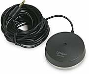
Editorial Note About Positioning the Denon Microphone ( Model# DMS-305) for Audyssey Set-up
It is strongly advised that the microphone be placed on a fixed tripod pointed straight up in the air for each listening position, or for greater accuracy pointed towards each speaker under calibration for every mic position. Because of the hockey puck shape of the Denon mic, it doesn't have a true omni directional response, thus any obstacle in its path or underneath it may adversely affect its ability to accurately read your loudspeakers. Placing the microphone on a couch or sofa may, depending on the material of the furniture, cause too much absorption or reflection, causing the Audyssey filters to excessively boost or cut certain frequencies - adversely affecting the calibration results.
I placed the hockey puck shaped microphone (optional accessory DMS-305 MSRP: $65) at my primary listening position and followed the prompts from the OSD.
Dealing with Error Messages During Calibration
 Any avid reader of Hitchhikers Guide to the Galaxy would tell you, " Don't Panic" if an error message pops up. Typical error messages include: L/R: None, L/R: Phase, Ambient Noise is too High. I personally received the L/R Phase error and was actually surprised to see it. Typically these systems will incorrectly identify a speaker out of phase if one of the drivers within the speaker is wired out of phase (this is typically done on the bass portion of 3 way systems to achieve proper integration at the crossover points). Oddly all of the drivers in my speaker system were wired in phase so I was unsure as to why I was getting this message. I decided to entertain the Audyssey system and wired my front speakers out of phase. To my surprise running Audyssey again revealed that my center channel was now out of phase. Still experimenting, I wired it out of phase just like I did with the fronts and reran the first step of Autocalibration. Bingo, no more phase error message. Recalling the article on MultEQ we wrote, I quickly realized that the Audyssey system was getting hung up on the absolute phase of each speaker which, to my knowledge, is an ability no other current room correction system possesses
There are two probable conditions which could cause this; 1) the speaker is electrically wired out of phase, or 2) the signal between the preamp and power amp has somehow been inverted. Since my situation didn't fit either of these two criteria, I was again perplexed by this, but decided to proceed with my front three speakers wired out of phase to make Audyssey happy.
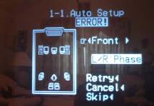
After calibrating for all eight microphone positions and allowing the AVR-5805 to process the information (this took about 5 minutes) I eagerly popped in a known reference disc to take a quick listen. I was a bit disappointed to hear very little bass impact or slam and wanted to get to the bottom as to why this was occurring. I took a quick frequency response measurement with my LMS measurement device and noted almost a 10dB suckout at the crossover point. I quickly realized that by changing the phase of the front three speakers without doing so with the subwoofers I had caused this suckout. I was puzzled as to why Audyssey didn't pick this up, especially since it allegedly can delineate absolute phase for all speaker groups. After running extensive phase sweeps between channel pairs using the Avia setup disc I determined that wiring all speakers (including the subs) in phase was the best course of action for my application and I rewired the system accordingly.
As a side note, I temporarily hooked up three two-way bookshelf speakers in place of my main front and center channels and reran the Audyssey test. It didn't report any phase errors. I could only conclude the unique driver array of my RBH Sound T-2 System was confusing Audyssey with respect to determining phase. When this occurs, Audyssey recommends wiring your speakers normally and skipping this test which is exactly what I did.
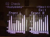 The OSD showed what at first appeared to be dismal one octave equalization curves. How could this be and where are the subwoofer curves? This system is far more sophisticated than that, isn't it? Thus I polled Chris on this and he told me that " in order for the correction curve to be accurately represented pictorially it would have required significant amounts of processing power from the Denon. Instead they opted for a basic display solely for illustrative purposes. Although it doesn't show curves for the subwoofer channel, the Audyssey system does function on that channel. Again, Denon didn't provision for a display on their OSD for this ." Satisfied and relieved with these answers, I proceeded with the calibration with an overwhelming anticipation to finally hear the results of this system in all of its glory in my own home theater environment.
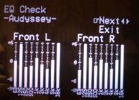 A quick listen revealed a more expansive soundstage, but also an overly energetic upper frequency response. The first time I ran Audyssey, I tried to take the easy way out and plop the mic down on the head of my couches at eight different listening positions. The end result was the system over EQ'ed my speakers, making them sound too aggressive and bright. The second time around I carefully held the mic and pointed it at each speaker for the primary four listening positions and then mounted it on a tripod for the other 4 positions firing straight up. In addition, since my speakers feature a truncated line array with a very large vertical baffle, I took a couple of measurements 2-3 feet above the two primary seated listening positions so Audyssey could better map the response of my front speakers. The end result was a much more natural and non obtrusive sound. Even the crude graphical depiction on the AVR-5805 showed less boost at high frequencies (especially in the 8kHz region).
Editorial Note on Post Calibration of Audyssey for Advanced Users / the Anal Retentive or Both
I highly recommend that experienced users check the EQ and calibration results with an Audio Analyzer or, at the very minimum, an SPL meter. I found the auto channel balances to be off by as much as 2dB if the mic wasn't carefully placed away from reflective surfaces, and nearly dead on (within +-1dB) if greater care was applied in the calibration process. Using the internal test tones of the Denon AVR-5805 won't be entirely accurate if you plan on using any of the EQ settings since the test tone mode bypasses all post processing. M y suggestion would be to use calibration discs such as Avia or DVE with your desired EQ mode engaged during the procedure to fine tune your response. Personally, I prefer a little bass boost in my response and nudged the subwoofer levels up about 4dB for more impact. If you only have 5.1 channel test disc such as Avia, you cannot calibrate the surround back channels, but you can swag it by interpolating the results of the 5 channel calibration between auto setup and the Avia or equivalent.
Note: Once Audyssey is engaged, a little green light will illuminate on the front panel display of the AVR-5805. If you alter any parameters of auto calibration, the light will change to red. If you wish to re-engage the auto calibration settings you can do so in the Auto Set-Up results parameter menu. The AVR-5805 even provides for three independent memory banks which can store auto calibration results and receiver settings and are accessible from the front panel.
Denon AVR-5805: Channel Calibration and Audyssey Measurements
|
Channels |
AVR-5805 |
DVE |
DVE |
Final Trim |
|---|---|---|---|---|
|
FL |
75.0 |
75.1 |
75.3 |
0.0 |
|
C |
75.0 |
75.5 |
75.5 |
-0.5 |
|
FR |
75.0 |
75.0 |
75.0 |
0.0 |
|
SRA |
75.0 |
75.0 |
75.2 |
0.0 |
|
SBR |
75.5 |
75.8 |
76.0 |
-1.0 |
|
SBL |
75.5 |
75.7 |
75.9 |
-1.0 |
|
SLA |
74.5 |
74.1 |
74.5 |
+0.5 |
|
*SWL |
78.0 |
78.0 |
80.0 |
+2.0 |
|
*SWR |
77.0 |
77.0 |
78.0 |
+3.0 |
|
Notes |
No Audyssey |
No Audyssey |
Audyssey Engaged |
Relative to Auto Cal |
*Difficult to read accurately on an SPL meter since results fluctuate more with bass frequencies.
I arrived at the final trim adjustments based on more advanced measurements using my Sencore SPC295 FFT Audio Analyzer and my ears (for the subs). While I am a fanatic about proper calibration, the Denon Auto Setup with Audyssey provided the most accurate auto setup I have yet to see in such a product. It correctly identified the speaker sizes, crossover points, distance compensation and approximate level trims which is great news for the non techno geek that wants instant gratification at the push of a button. As a reminder, following the calibration guidelines established herein will achieve the most accurate results. Take your time to do it right and you will be rewarded. Don't forget that any time your room undergoes a major change in orientation (i.e. furniture move, adding curtains, etc) you must recalibrate to achieve the best results. M y advice is to store the mic in a safe place for future usage.
Audyssey Measurements
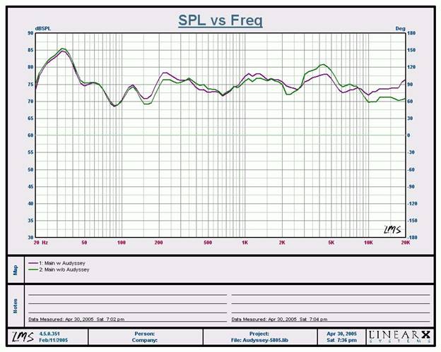
In room, on axis measurement at the primary listening position, 1/3 octave smoothed
The Green trace represents the summed frequency response of my main channels and subs without Audyssey, while the Purple trace represents the same measurement with Audyssey engaged. As you can see the high frequency response past 8kHz is greatly improved and extended while the midrange performance between 3kHz to 6kHz is flattened out to match the overall response. I was surprised to see very little difference in low frequency performance, especially since I did hear an improvement in my listening tests. I can only attribute this to the fact I am using an analog input of the AVR-5805 and the Audyssey LFE filters may not be engaged when this type of signal is present.
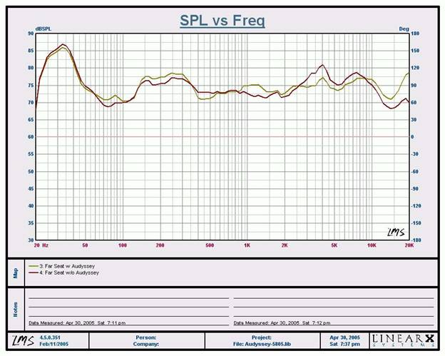
In room, on axis measurement at a far listening position, 1/3 octave smoothed
The red trace represents no Audyssey, while the gold trace represents Audyssey engaged. As you can see the overall frequency response is smoother and better extended with Audyssey engaged. What's most interesting here is that this mic position wasn't even placed at the exact position Audyssey calibrated for. Basically the spatial mapping of Audyssey was also improving the system's frequency response even at areas in between calibrated microphone positions.
Note: We are checking with Japan to verify that the latest firmware version has been installed. In conversations with Audyssey, their results indicate we should be seeing more effective bass correction than these measurements reveal. A review addendum will follow once we have more information.
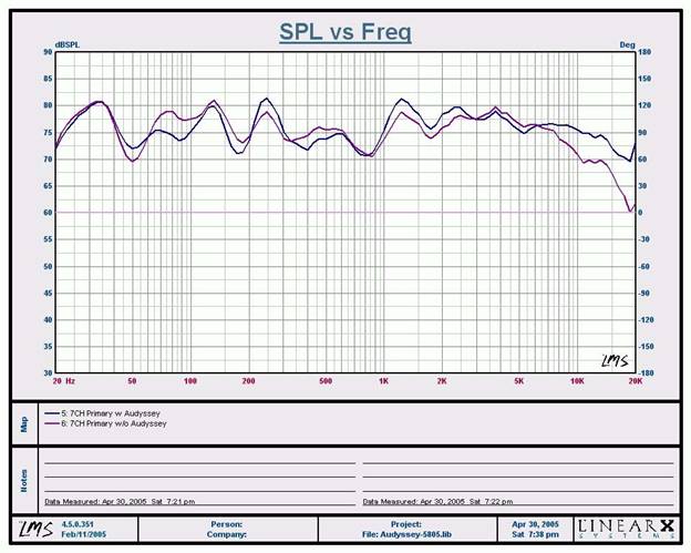
In room, mic vertically oriented at primary listening position, 1/3 octave smoothed
Just for fun I pointed my LMS mic straight in the air at my primary listening position and engaged 7CH Stereo mode on the AVR-5805. The purple trace represents no Audyssey, while the blue trace represents Audyssey engaged. It's quite impressive as to how much flatter and more extended the system's high frequency response from 5kHz to 20kHz is when Audyssey is engaged. The overall low end response also seems a bit flatter, probably due to the summed flattened response of all the channels.
Denon AVR-5805: AV Configuration
Configuring the audio and video sections was fairly straightforward. All of the audio and video I/O's are user assignable. Each input has priority settings for audio and video signaling along with auto detect. The most outstanding feature I found was the receiver's ability to remember surround modes for each input and source type independently!
For example, on the DVD input, I selected PLIIx Movie mode for Dolby Digital Sources and PLIIx Music mode for DTS. The AVR-5805 remembered this configuration each time I toggled between different formats and inputs. If the surround mode doesn't work well for your particular disc you a reusing, don't sweat it. The remote control has hot keys for toggling between surround modes. This even works for two-channel sources. I would have really liked the option of permanently storing PLIIx modes for each input and source type like on the Integra Research RDC-7.1, rather than it just remembering the last setting. But, I am nitpicking here, especially given the flexibility the AVR-5805 has and the fact that the user is likely to select different surround modes depending on the source material anyways.
Configurable Power Up Volume and More
 Alas, Denon has finally included a configurable power up volume control and max limiter feature. This was a necessary feature missing on their receivers until now. They also provided for independent master trim settings for e a ch input. This feature is important when two different sources of significantly different signal levels are utilized in the same system. This ensures you won't get blasted out of your couch when switching between a music CD and your CableTV, for example. Another useful feature (especially if you have kids or estranged visitors frequenting your home theater room) is the ability to enable a max volume level setting as well as a stored power up volume setting. I can't tell you how many times a family member tried to operate my system while I wasn't present, couldn't get any sound, and figured the only cure was to keep pumping the volume up only later to happen on pressing the right input and getting scared out of their pants while almost blowing out a speaker or, in my case, tripping a circuit breaker. Denon recognized this and made a failsafe option to prevent your system from self destruction caused by the neophytes attempting to operate something they shouldn't. This is the best solution short of electric shock treatment.
For all you video buffs, you will be happy to know the AVR-5805 has independent A/V Sync in 1ms step sizes (up to 200ms), so you can resolve any lip-sync issues that may arise when using the scaling and video processing capabilities of front projection systems or external processors that may delay the video signal.
Got Triggers?
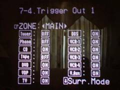 One of the biggest contentions I have with many of the receivers and processors on the market is their anemic trigger system. Sure most of them have the standard 12V trigger, but read the fine print. In most cases, they supply 12V to 20mA or less. This is not enough current drive to operate most power centers and motorized screens. Refreshingly, Denon supplies four (count them 4) high current 250 mA triggers configurable for Zones, inputs and even surround modes which is useful for toggling trigger-enabled speaker systems between dipole, bipole or monopole assignments making it the most comprehensive trigger system ever conceived in a home theater receiver. Denon really did their homework here and I am sure many custom installers are as delighted as myself about this.
Note: Be sure to enable "on" for all inputs if you require certain devices to be always on whenever the receiver is powered up. I forgot to do so for my CD player and found it kept shutting off each time I toggled to a different input until I realized why.
Video Setup
Yet another cool new feature of the AVR-5805 is the inclusion of HDMI video switching and audio processing. The AVR-5805 is one of a scarce few receivers or dedicated processors that offer this feature. In fact it is the world's first HDMI 1.1 consumer compliant product (a point which Denon doesn't tout as much as they should). While we're certain others will eventually catch up, currently, Denon has the only commercially available product line of HDMI 1.1 compliant receivers and DVD players via the latest Silicon Image chipsets,. Considering the fact that HDMI 1.1 has yet to receive approval for digital transmission of SACD, IEEE 1394 is still the only all-inclusive digital interface for all mainstream digital multi-channel formats. Thus the best solution in this case is HDMI for video and IEEE 1394 for audio.
Editorial Notes about HDMI (especially for computer folks)
You cannot connect display devices (such as presentation displays) that are NOT HDCP compliant. The result if you attempt this will be no picture. Note: A firmware update (this summer), will remove HDCP compliancy from the AVR-5805, so it will pass non-HDCP encoded material to non-HDCP compatible sets. The AVR-5805 currently does not support analog video upconversion to HDMI (a feature currently supported only by Denon's new AVR-4806 and as an upcoming upgrade this summer to their AVR-5805). However, the AVR-5805 does support Component Video Up Conversion so it's a good idea to use this feature when handling composite, s-video and component video connections.
I was thrilled that Denon included I/P conversion and scaling video processing for zone 1. They even provided for video conversion, but no scaling for Zone 2. Denon realized that many of today's antiquated recording devices such as VCRs require Time Base Correction (TBC) circuitry to operate properly when engaging video processing. Many of the newer econo box VHS machines no longer offer this as a standard feature. With this in mind, Denon provided this feature which I found to work flawlessly on my JVC VCR (yes I still use it). TBC will help video sync the signal for such instances.
Video Processing
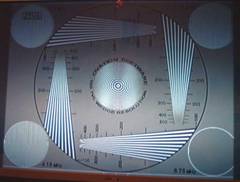 Denon offers some very unique video processing features in their latest flagship receiver found only on a few competitor super receivers. Digital video upconversion and DCDi processing is powered by Faroudja. The integrated digital processing in the AVR-5805 lacks the picture adjustments (brightness and contrast, sharpness, saturation, 3D NR and cross color suppression found on the Yamaha RX-Z9 . But, considering the RX-Z9 applied this globally for all inputs, it almost made these features impractical to use. Since most modern displays have independent picture settings per input, it's better to do all of your picture adjustments at the display. The AVR-5805 also does video scaling and upconversion of interlaced 480i signals to 480p/576p, 720p and 1080i as well as aspect ratio control or pass-through for both PAL and NTSC display types. Be advised however that copyrighted signals such as DVD, will not be processed above 480p via the AVR-5805 even if you select higher resolution settings. If you have a DVD player such as the Denon DVD-5900 which does video upconversion to 1080i via DVI, you may be better off going that route to your display. In fact, I found that when the Denon Video Processor was enabled (1080i), the Avia resolution test was now displaying resolution limits of about 480 lines, as compared to over 500 lines of resolution when the DVD-5900 did the de-interlacing via its component analog outputs at 480p. The 6.75 M Hz test window was displaying discernible vertical lines, but not as sharply as when the DVD-5900 was used as the de-interlacer. There was however a tad less jitter with the AVR-5805 deinterlacer, but only when engaged in 1080i mode. Since component video outputs of compliant DVD players are limited to 480p, this wasn't an apples to apples comparison. The end result is use the AVR-5805 video processing features on poor quality video sources and/or DVD players with sub par deinterlacers. I used the AVR-5805 for all of my composite video and s-video sources. For progressive video sources such as those from progressive scan DVD players, the digital processing of the AVR-5805 is bypassed, as it should be, even if you have it set to a particular scaling mode.
 Even on old VHS tapes such as one of my favorites, Mars Attacks, I noted a slightly more dynamic and smoother, almost film-like picture with the AVR-5805 video processing engaged. M ars Attacks was a great demo tape to really show off the AVR-5805's ability to transform an old VHS classic into a modern day pseudo 7.1 surround sound spectacle approaching DVD picture quality. In contrast, my daughter's tapes such as Cinderella looked equally as bad. Luckily no flickering was introduced into VHS tapes with the AVR-5805 video processor engaged as it was when using the RX-Z9. The TBC feature on the AVR-5805 was responsible for eliminating this as an issue.
I found the HDMI video switching to work flawlessly . My only gripe was the AVR-5805's inability to support OSD via HDMI. However, this will soon be remedied with a firmware upgrade late in the summer of 2005. When using HDMI check to see if your DVD player provides squeeze modes to this format - many players do not. Squeeze mode is essential to properly play back 4:3 DVD material on 16:9 displays. Thankfully the newer DVD-5910 (review pending) has an auto squeeze mode that also works for HDMI. It was a bit of a pain each time I viewed a 4:3 source on my 16:9 display to go into the user control menus to select the correct aspect ratio. I am hopeful that all new HDMI-enabled DVD players will offer an auto scaling feature via HDMI to eliminate this inconvenience.
Editorial Note on HDMI (High Definition Multimedia Interface)
HDMI (High Definition Multimedia Interface) is a trademark of HDMI Licensing, LLC. Developed by Sony, Hitachi , Thomson (RCA), Philips, Matsushita (Panasonic), Toshiba and Silicon Image, HDMI was created as a digital interface standard for the consumer electronics market.The HDMI protocol combines high-definition video, multi-channel audio, and inter-component control in a single digital interface. This lone interconnect has the ability to transmit uncompressed digital video and up to eight channels of audio from source to display. Even more, the HDMI connection enables audio/video components to share data and commands, thus unifying an oft-disjointed collection of "boxes" into a real, working system. Based on Silicon Image's TMDS technology, HDMI is also fully compatible with PCs and display devices incorporating the Digital Visual Interface (DVI) standard.
For more information on HDMI Connections check out Audio & Video Connections - Definitive Guide
Denon AVR-5805: Surround Processing and Bass Management
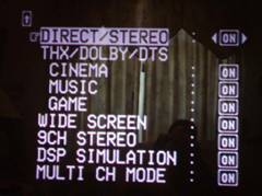
The AVR-5805 is fully armed with all the latest surround modes including PLIIx, DTS Neo, DTS 96/24, THX Ultra 2 as well as their own proprietary surround modes which I found to be unusable especially after hearing some of the awesome modes that Integra Research and Yamaha offer in their flagship products. Denon realizes this and has no desire to offer a multitude of artificial DSP modes. While I can see arguments from both camps on this topic, to be honest I only utilize such DSP on rare occasions such as when viewing older concert DVDs and VHS tapes which usually benefit from a good DSP mode. In those instances I found partial salvation using PLIIx M usic M ode. What's re a lly cool is that you c a n overl a y PLIIx over virtually any audio signal or format (i.e. Dolby Digital, DTS, DVD-A a nd SACD tr a nsported through IEEE 1394!) Now you can have your cake and eat it too by taking advantage of all 7 speakers in your setup regardless of what format is being decoded.
All of the THX options are also present, including Ultra 2 Music, Cinema , EX, and the newest THX Games mode. But be warned, engaging any of these modes automatically restores the bass management to a global 80Hz crossover setting. Thus, if Audyssey determined more optimal settings for a better splice between your speakers and subwoofers, it will be lost when engaged in THX post processing modes.
Learn More About the Different Levels of THX Certification at:
THX Certification Levels Explained
Bass Management
 The AVR-5805 bass management system is by far the most sophisticated and flexible system we have seen in a receiver or even a dedicated processors for that matter. In fact, it uses one dedicated 32 bit TI chipset just for that function! It allows user adjustable speaker group crossover frequencies independently of each other from 40Hz to 250Hz and independent subwoofer delay and level settings for up to three subwoofers! It even allows for independent subwoofer crossover settings for two-channel audio. I proceeded with caution based on my past experience with systems that attempted, but failed, to successfully offer this type of multiple crossover system. The problem with most multiple crossover systems is when you configure one speaker group's crossover to a much higher setting than the main channels, the bass from those speaker groups don't get recombined to the sub and are lost entirely. This is because most systems only incorporate one fixed LPF setting for the subwoofer channel which is usually derived from the main channel's setting. Knowing the kind of company Denon is, I didn't suspect the AVR-5805 truncated the bass like this, especially since it has a separate LFE crossover setting.
To test my assumption, I used the Audio Precision SYS 2722 Audio Analyzer to run some measurements via the analog two-channel inputs of the AVR-5805 configured in two-channel and multi-channel surround modes. What the SYS 2722 told me was that the LFE crossover setting only affects LFE info as stated in the menu. This is a good start, implying if you set all other channels to a lower frequency, critical LFE info will NOT get truncated. Many processors unfortunately do truncate LFE bass under this circumstance but thankfully the AVR-5805 is not one of them.
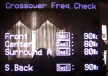
Discrete Multi Channel Measurement
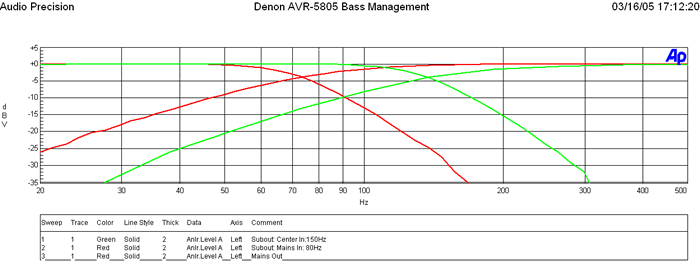
Red Traces: Main CH set to 80Hz and corresponding subwoofer output
Green Traces: Center CH set to 150Hz and corresponding subwoofer output
This is a plot of the subwoofer LPF and Main Channels HPF when set to the THX recommended 80Hz crossover setting (in red) and the center channel set to 150Hz along with its corresponding subwoofer output (in green). Notice in the red trace the HPF is down -3dB at 80Hz with a 12dB/Octave slope while the subwoofer is -6dB down at 80Hz with a slope of 24dB/Octave as per THX. Similarly for the center channel and corresponding subwoofer output at 150Hz the -3dB point of the HPF is 150Hz and the -6dB point of the LPF is 150Hz. Basically the AVR-5805 bass management is intelligent enough to have discrete LPFs corresponding to the HPF settings of each channel group. For 2CH sources, the LPF of the subwoofer is based on the HPF setting of the main channels as it should be.
A few notes about bass management logic for the AVR-5805:
- If you set Mains Small, all other speakers default to Small
- If you set any speaker to Large, the bass will not go to the subwoofer, except if you select "LFE + Main ".
- If "LFE + THX" is selected then bass from the Mains will not be directed to the subwoofer if the Mains are set Large, even in 2CH mode.
- The AVR-5805 has completely independent bass management settings (ie. crossover, distance compensation, level, etc) for 2CH mode. Not since the days of the Aragon Soundstage have we seen this sort of flexibility, especially in a receiver!
Editorial Note
The reason for asymmetric filter responses between the HPF and LPF is to account for the natural roll off of the satellite speakers which is typically 12dB/octave. This allows the best blend between the subwoofer and satellite system.
PLIIx Measurement with Analog Two Channel Source
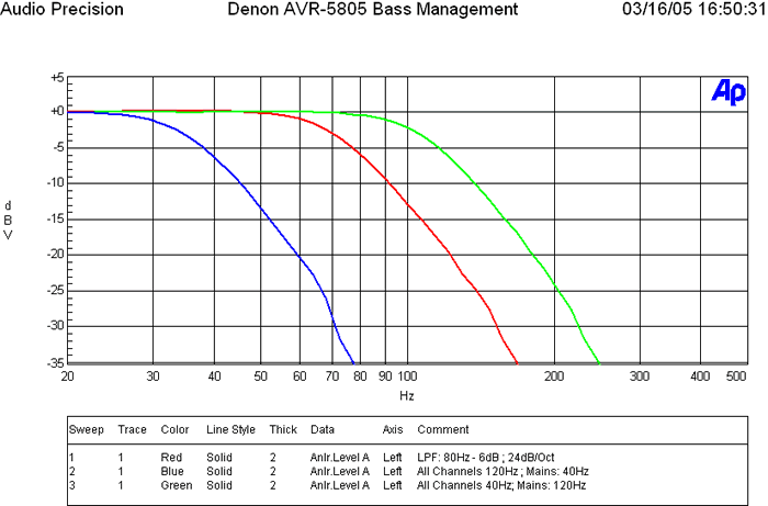
The Green Trace represents the subwoofer output while the main channels are set to 120Hz while all others are set to 40Hz.
Notice the subwoofer output that appears to be rolling off at 120Hz which is based on the main channel setting.
The Red Traces represent all channels set to 80Hz. Again notice the subwoofer crossover point remains at 80Hz based on the main channel setting.
Let's take a closer look at the subwoofer output while varying the multiple crossover settings between the main speakers having high and low crossover settings, while the other speakers have low and high crossover settings, respectively. The AVR-5805 is configured in PLIIx Music Mode.
In the Blue Traces, we set all channels but the mains to 120Hz (extreme case), while the mains were set to 40Hz. Notice how the subwoofer crossover -6dB cutoff remains at 40Hz based on the main channels setting and we see no weird summing like we did in the Integra Research RDC-7.1. Granted, ideally it should have extended to the frequency of the satellite speaker with the highest crossover setting (in this case 120Hz), but I suspect Denon limited the cutoff of the LPF of the sub to the main channels setting to avoid excessive bass energy from a single source which is localizable at frequencies above 80Hz and to avoid having too much overlap of the speakers with HPFs set to a lower value.
Essentially the bass information from any speaker groups set above the main channels crossover point will not recombine bass back into the subwoofer. In other words, that information will be lost or extremely attenuated. In actuality the function is proper since the AVR-5805 was receiving a two-channel source and deriving a multi-channel surround output. It was defaulting the LPF of the subwoofer to whatever setting the main channels were configured too.
Overall, this multi-crossover system is the most flexible bass management system to date (a requirement for properly integrating the Audyssey MultEQ room correction system), and can be very effective if used within confined limits. We would suggest to always select satellite speaker systems with a -3dB point of 80Hz or lower, especially when using a product of this caliber in a full-blown high performance home theater system. We also suggest maintaining a difference of no greater than 20Hz between crossover settings of all speaker groups and using caution when setting the main channels' crossover setting too low (especially when listening to two-channel sources in surround sound) to avoid loss of bass information from the other channels. Always start at the 80Hz reference point and only deviate when absolutely necessary for your particular situation. In my system, I set all channels, including the LFE, to 80Hz (THX setting) except for the main channels which I set to 100Hz because I achieved better acoustical bass integration with my subwoofers and main satellite speakers.
Denon AVR-5805: RC-995 Electroluminescent (EL) Universal Remote Control
 Pros
Pros
- Automatic wake/sleep mode that works really well
- Super easy learning remote functions and presets
- Punch-through support for programmed/learned functions
- Adjustable backlight time
- Lighted volume and channel keys
Cons
- Very difficult to see display in sunlight (even at brightest setting)
- Hard to push Coleco Vision style functions keys
- Limited function control of manufacturers' equipment
Denon employed a very similar retro styled remote from the AVR-3805 . It features an Electroluminescent display which is essentially the same technology employed by LCD backlights. Electroluminescence is simply light (radiant energy) created by an electrical field that does not result in heat. In fact, ELDs could be thought of as inefficient capacitors that lose energy in the form of light. Current ELD life expectancy is around 100,000 hours at 75% of original luminance - that's probably longer than you will use this receiver!
The luminous blue color of the buttons is merely the backlight being allowed through the insulating surface that covers the remote's functions. Each function, or button, has its own parent EL area and the EL backlight is configured so as to allow different buttons to become lit when certain modes are engaged. The remote feels big in your hand, and indeed it is over 9" long and nearly 3" wide at its top and bottom. There is no real ergonomic shape to the remote, except for a slight taper around the midsection. The physical buttons available on the remote are channel up/down, volume, channel select/enter and a 4-way cursor/menu control button. I am not a particular fan of LCD-style remotes, and the Denon RC-995 shares the same downfalls in that it commands your attention in order to use functions not related to volume or channels. For example, want to record/watch a show on DVR, change the display mode of your HDTV, or bring up the guide on your cable box? With the EL remote, you have to look at the screen after the backlight comes on, and select the correct function. A tactile button-based remote allows you to simply navigate by feel to your more commonly-used functions.
Source Switching
Pay attention to the source buttons or they may throw you. At first glance you'll wonder how on earth your fingers will select between the amp and tuner buttons (perhaps a plastic pointer stick commonly used at shopping checkouts with LCD touch panels would be appropriate.) I couldn't help but have flashbacks of my childhood gaming days playing on systems such as Intellivision and Colecovision, remembering my frustrations the flat panel keypads evoked at the time, probably one of the reasons I gave up gaming long ago.
In actuality, the source buttons "toggle" between two or more devices each time they are pressed. Pressing VCR/12 activates VCR1 on the first press, and the screen visually references VCR2 if pressed again. The same is true for ZONE2/ZONE3, CD/CDR, DVD/DVDR, TV/DBS/CABLE, AMP/TUNER, and TAPE MD. All in all, the remote control enables easy control over all equipment once you program it, which is an easy process - one of the more straightforward methods I've seen. Controlling unusual functions such as the variable "aspect ratio" on my Sony 51WS-500 HDTV means you'll have to assign a function to whichever available button you can find. This problem isn't unique to EL remotes- it also exists on remotes with physical buttons. Going back to my earlier statement, however, at least with an LCD remote you can customize the display.
Alas an added and much needed feature absent on the AVR-3805 remote control is a "Video Select" option which is also found on the front of the AVR-5805 receiver. This feature allows you to select a different video source while listening to the current audio signal. This function effectively allows the user to do things such as listen to a DVD or CD while you browse the web on an H TP C (assuming you connect all video through the Denon's switching video inputs.) I was glad to see this option on both the remote and front panel display. As I previously mentioned, the SRC On/Off buttons on the LCD panel below the main on/off push button power is an excellent feature and safety precaution. This allows you to turn off the main zone to prevent users of other zones of messing up your primary settings. This is a very useful and thoughtful feature that I am sure many users will be thanking Denon for when they configure the AVR-5805 as a full multi-zone controller.
The remote is not perfect, but in defense of Denon, they are not in the remote control business. In addition there are great cost effective solutions from companies such as Harmony or Universal Remote that will get the job done - and then some. Anyone plopping down 6000 clams on a product of this caliber can probably afford to spend $200-$500 on a good remote control. Hey, it's a much better investment than battery powered exotic cables (with exception to the Audioholics GLOB Cable of course) :)
Denon AVR-5805: Sound Quality Tests
What good is a feature packed receiver (or any A/V gear for that matter) if it cannot deliver the goods in sonic performance? Our viewpoint is sound first, features second. With that, here is my subjective impression of the AVR-5805 for the gamut of playback modes I put it through.
Two-Channel Audio
 I always begin my initial listening tests in two-channel since I am a two-channel audioholic at heart. I always tweak my system to get the front soundstage optimized prior to getting into any multi-channel listening sessions. I began my review with some familiar tunes from a CD I picked up in Canada visiting Axiom Audio called "Mediterranean Nights" by Vehkavaara & Piltch. I took note of the smooth and melodic melodies of this CD with an extremely low noise floor. The bass extension was very pronounced both with and without the Audyssey system turned on, though I felt the integration between my satellite speakers and subs was improved with it on. Toggling the Audyssey system on and off I could hear a dramatic improvement in detail and focus with it on. With my initial calibration of the mic placed on the couch, I found the results to be a bit bright, though it wasn't raspy or ear piecing like I experienced with other room correction systems. My second calibration in which I extended far more care and time achieved much more musical and unobtrusive results. Audyssey excelled here nicely. I certainly liked what I was hearing - so much so that I found myself disappointed each time I switched it off. It sounded as if the music was somewhat deflated and dull without MultEQ engaged.
 The amplifier section of the AVR-5805 proved to pack what seemed to be much more punch and weight than its published specifications. I was able to really crank this CD for long periods of time in both two-channel and PLIIx M usic modes without the amp even giving indications of being stressed. Switching over to one of my favorite Pat Metheny CDs Off Ramp , I skipped over to track 2 "Are You Going with Me?" and waited for his synthesized guitar solo where he wails for several minutes. It sounded so darn good that I got lost in the moment and just kept pumping the volume up. Here I was with 9 channels (front channels in bi-amp mode) driving me to oblivion in my 28' x 18' living room with vaulted ceilings, showing peaks on my SPL meter in excess of 106dB - yet the AVR-5805 had more power to spare. For those riding the "all channels driven" bus, this should more than satisfy your concerns that the amp section in this receiver is powerful. With this power comes a penalty - heat. The heat build up was rather dramatic after about 1 hour of sustained high power output. This is a potential problem even when the amp sits idle which is why plenty of ventilation and free flowing air is recommended.
Two-Channel SACD
My true fidelity test is how well a product can stand up to some of the well-recorded SACD discs from Premonition Records. Listening to SACD via IEEE 1394 was a luxury afforded only by two other products we have reviewed to date - the Yamaha RX-Z9 and the Integra Research RDC-7.1 (though this was unfortunately problematic with our review unit).
For those worrying about the AVR-5805 passing subwoofer information in two-channel mode - fear not, as it does handle bass management via its IEEE 1394 interface much like when decoding DD/DTS. While some would argue converting DSD to PCM to facilitate this may result in sonic degradation, I would counter with "But can you really hear a difference?" If implemented properly, there shouldn't be any ill effects and, in my opinion, the benefits of having bass management and digital delay compensation in this case far outweigh such concerns.
SACD: Patricia Barber - Café Blue
This, as well as the other three Patricia Barber recordings by Premonition Records, remains one of my benchmark SACDs for good reason - it features lumpy jazz in a smooth jazz environment free from compressive artifacts. You won't find repetitive and annoying saxophone scales, single stroke drumming, and simplistic guitar rifts. Instead you're showered with snappy jazz and provocative lyrics, slamming drums, and memorable instrumental solos. The SACD layer of Track #2, " Morning Grace " sounded phenomenal, especially with Audyssey engaged. Listening to the AVR-5805 via IEEE 1394 for SACD was nothing short of stellar. The noise floor was virtually nonexistent and the system bass integration was worthy of a standing ovation.
Some Notes About IEEE 1394 / Firewire1) IEEE 1394 is a balanced interface. The modern "low voltage differential serial" interfaces are *all* based on the original work done to develop Firewire back in the early '90's. The low level interface is a pair of LVDS signals (2 pair) in addition to very aggressive grounding for those systems that are not galvanically isolated (the "b" form of 1394 supports both copper and optical connections, and the copper connections can be transformer coupled if necessary).
2) The amount of jitter for audio applications is arbitrarily small. The IEC 61883-6 transport method used for IEEE 1394 allows each audio source to provide its own sample clock, and the sync can follow that clock with arbitrary accuracy and stability. It's totally up to the system cost budget how stable the PLL must be. For more information on this, suggestive reading material on this topic can be found at: http://www.1394ta.org/Press/2003Press/january/White_paper.pdf
3) The AES (Audio Engineering Society) has been working with IEEE 1394 specs for some time, and the experts there have no problem with the quality of 1394-based transports. There are a few AES specs based on IEEE 1394 networks.
Note: IEEE-1394 / Firewire / IEEE 1394 / Lynx are all names describing various manufacturers' depictions for cables belonging to the IEEE 1394 standard. IEEE 1394 is the new, extremely fast external serial bus standard that supports data transfer rates of up to 400 Mbps (400 million bits per second). It is used primarily for multimedia devices such as camcorders, computers, digital audio recording workstations and, in this case, a digital transport for high resolution audio.
Multi-channel Audio
DTS CD: Steely Dan - Gaucho
I always start off with my base DTS CDs for a quick sanity check. The reason is because I intimately know how these discs should sound, and they usually provide me a clear indication of when I have configuration issues. Steely Dan's Gaucho is one, the Alan Parsons Project On Air is the other.
When I hit play, I immediately heard the classic DTS fizzle sound that has been pretty much absent in most products for the past several years. I was surprised that the AVR-5805 didn't include a muting function during DTS lock on and search. I also found this issue with the Integra Research RDC-7.1 we recently reviewed and wondered if it was somehow attributed to the Texas Instruments chipset. Further investigation is needed here.
Audyssey extracted the detail of multi-channel recordings bringing an elevated sense of realism but didn't offer much assistance with already bright recordings such as Porcupine Tree's In Absentia. Certain tracks of this recording are almost intolerable at high volume levels and Audyssey did not help in this capacity. Thankfully it can be turned off on the fly in situations like these or you can increase the bass levels using the on-the-fly channel adjustments to compensate.
DTS CD: Eric Clapton - One More Car One More Rider
Overlaying PLIIx Music Mode on the wonderfully recorded DTS soundtrack of Eric Clapton's One More Car One More Rider concert DVD was an enthralling musical experience. Audyssey really squeezed out all of the nuances and details of the recording, though the audience clapping after each song became a bit overbearing and I found myself lowering the volume after each song in anticipation. But Eric Clapton's guitar seemed to fill my living room while Steve Gadd's brush strokes on the drums seemed ever so closer and more intimate with Audyssey engaged. I really dug how the tracks "Reptile" and "My Fathers Eyes" sounded with Audyssey engaged and found myself progressively increasing the volume control to ludicrous levels until my wife intervened. I was truly impressed with the dynamic capabilities of the AVR-5805. With my RBH T-2 System biamped off the AVR-5805 I had 9/10 channels of the receiver belting out high SPL levels with no signs of distress, compression, or nasty edginess found on most A/V receivers when pushed beyond their limits. If there were limits to the power capabilities of the AVR-5805, I haven't found them yet.
Listening to DVD-A via IEEE 1394, Audyssey MultEQ and PLIIx Music mode was simply awesome. The percussions of Blue M an Group were very enveloping, especially with Audyssey engaged. Graham Nash's " Chelsea Hotel " is one of those songs you find yourself continually increasing the volume simply because it sounds so good. I loved watching the screen on my RPTV resonate each time the bass waves slammed in my room. With Audyssey engaged, the splice between the speakers and subs seemed more fluid and natural sounding.
7 CH Stereo
 Ever since I married into a Colombian family, the word "Party" took on new meaning. In my experience, nobody parties like them. Lots of people, food, dance, and extremely loud music into the early hours of the morning is their norm. With that, I found the most appropriate mode on the AVR-5805 when entertaining such events was the 7 CH Stereo mode. Whether we were listening to Carlos Vives or a personal friend of our family Larry Duran (master accordion player and vocalist), the Denon rocked the house. Listening to Larry's title track "El Merendon" revealed the true workhorse nature of the AVR-5805. The accordions and vocals filled the room with sound and evoked the 'spirit of the dance' with our family and guests. We were able to hit the insane SPLs that these party goers crave without sensing any loss in headroom or compression from the internal amps. Personally, I feel 7CH Stereo can be a bit overpowering, but thankfully Denon understands this which is why they incorporated a feature for shifting the balance of sound from rear to front and vice versa (essentially a fader control) simply by tapping the enter key on the remote and scrolling through the OSD speaker level adjustments until you reach that adjustment.
Home Theater
My movie watching experience hasn't been this enjoyable since I first discovered discrete surround sound! I felt as if I reached the next evolution in high performance home theater when engaging the Audyssey system. The amount of detail and the realism of the panning from the front to back sound field was stunning to say the least. But Audyssey can't take all the credit. The processing and amp sections of the AVR-5805 are simply phenomenal. It's dead quiet when it should be, bold and dynamic when called for. As with many other modern 7.1 receivers and processors, I loved the fact that I could transform standard 5.1 DD DVD's to 7.1 via PLIIx processing and felt it really added a sense of realism and envelopment to the movie watching experience. If you are contemplating on whether you wish to integrate the extra two back surround channels, just do it! Find a way to make it work as it will be worth your while. Denon actually allows you to add an extra pair of surround speakers and has the amps to power them to boot. This is an awesome advantage for very large rooms that have many rows of seating requiring more coverage.


The action scenes from The Incredibles are simply awesome. This disc has quickly become one of my reference DVDs, not just because of the stellar sound and video quality, but for its awesome story line and fun-factor. Engaged in DD EX mode, I toggled between Audyssey and no Audyssey during the jungle chase scenes with Violet and Dash and with Audyssey engaged, the scenes were far more enveloping. The surrounds seemed to come alive both in realism and in uniform coverage throughout all of the primary listening positions. Dialog intelligibility was also enhanced with Audyssey engaged. I noted similar experiences during the collision scene between the Enterprise and Shimitar in Star Trek Nemesis. Oceans Twelve was a cool DVD to further demo Audyssey's prowess during intensive dialog and music scenes.
I found Audyssey to do well with music, but truly shine with movies. Anyway you look at it, it's a great tool to ad to your bag of tricks for improving system performance and increasing playback enjoyment.
Denon AVR-5805: Measurements and Analysis: Preamp Section
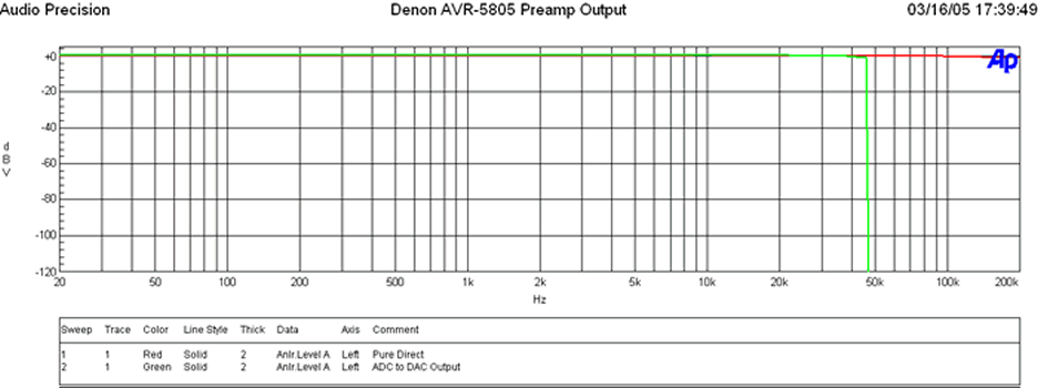
The green trace shows the frequency response via the analog inputs when engaged in a DSP mode and going through ADC and DAC conversion stages. As you can see, the frequency response is ruler flat past 20KHz followed by a sharp brickwall filter response rolloff at ½ nyquist frequency of 48kHz (96kHz sampling rate). The Denon upsamples all 44kHz signals to 96kHz / 24 bit as per their AL24 bit process. In fact, Denon's Advanced AL24 Processing handles up to 192kHz and 24 bit extension with real time interpolation.
Denon Advanced AL24 Processing Benefits (according to Denon)
- Frequency response expansion
- In addition to the bit extension by conventional AL24, the amount of information of music reproduction is expanded by performing interpolation on a real-time axis with original high-speed signal processing technology.
- Real time variable filter
- In order to perform reproduction optimal to high sound quality, Advanced AL24 detects signal changes in real time, where a trigger is generated to change dynamic filtering
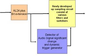
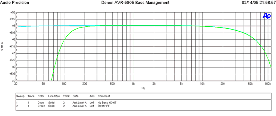
The light blue trace represents analog output frequency response of the main channels via analog input signal with no bass management applied. The green trace represents the bass management applied with a crossover setting of 80Hz. Notice that no A/D to D/A conversion stage took place to apply bass management as indicated by the lack of brickwall filter response at high frequencies. At first, I didn't understand this until I pinged Denon and they informed me of a completely independent bass management system done in the analog domain to ensure a true analog signal path was maintained. Audiophiles and fanatics can rejoice. Now you can have a true analog bypass with proper bass management (if needed). This is a truly incredible and thoughtful feature.
Note About Pure Direct Mode
When configuring Pure Direct mode, I recommend setting it to the "Basic" bass management option first so it copies the front channel distances that were established during auto setup. Afterwards, you can select "Custom" if you desire to change the crossover setting or even the distance compensation. Note however that distance compensation in Pure Direct mode and all modes for that matter can be fine tuned to 0.1ft increments if you enable this accuracy in the main speaker distance set-up menus, otherwise it will default to 1ft resolution (the typical limit of most costlier processors).
Denon AVR-5805: Preamp Measurements Cont
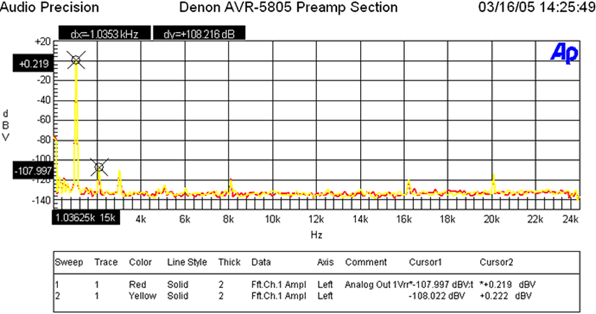
When the analog preamp was driven at 1Vrms (typically ½ signal strength to achieve ½ of max power of most power amps with voltage gain of 29dB) distortion levels were (+.0219 + 107.997)dBv = 108.216dBv (about 7dB better than what I measured on the Integra Research RDC-7.1 Processor ) or 100*alog(-108.216/20) = .000388%! The yellow trace represents "Pure Direct" mode, while the red trace represents normal stereo. As you can see they are virtually identical in performance which is testament to the excellent noise mitigation and layout of the receiver even when all functions are active.
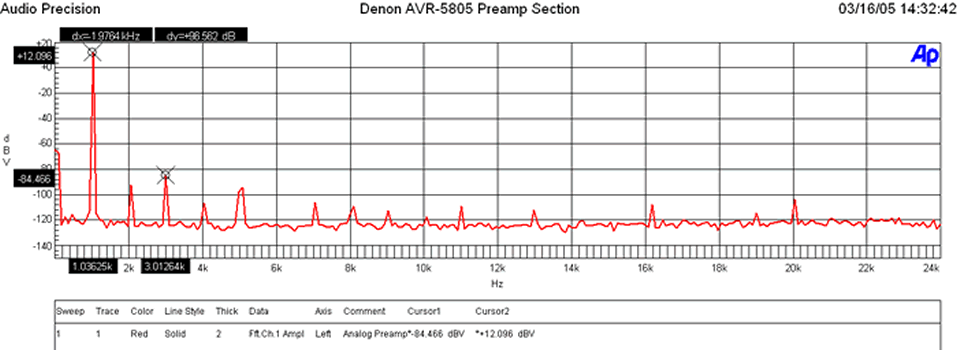
When I drove the analog preamp to over double the voltage required to achieve max gain of most power amps (4Vrms) distortion levels were very commendable (+12.096 + 84.466)dBv = 96.562dBv or 100*alog(-96.562/20) = .00149%!
Note: The preamp section of the AVR-5805 is benchmark regardless of receivers or processors. The Inputs can handle 10Vrms unclipped while the outputs can deliver 8Vrms unclipped! The preamp gain is (Av = 5.78) or 15.2dB. Most consumer equipment (i.e. CD players, VCRs, etc) drive 1-2Vrms max via their analog outputs so there shouldn't be any compatibility problems here. If for some reason you find the input levels too high, causing clipping, the AVR-5805's independent level trims for each input will come in quite handy.
This is great foresight on their part, though in all likelihood the expected use of this feature is more for level matching sources than eliminating preamp clipping given the awesome headroom of the Denon preamp section.
Ch-A SIGNAL to NOISE RATIO
- -116.62 dB below 18.49 dBV Reference Level (at 1.04 % THD+N)
- < 10 Hz - 22k Hz bandwidth , no option filter.
- This is out of the preamp out. Thus at 8.4Vrms -116.6dB SNR
With a 200mV Input Signal, I adjusted master volume for 1Vrms out, preamp gain (Av=5 or 14dB), and measured as follows:
- -20.452 dBrA with signal
- -116.419dBrA with signal
Thus the SNR was 96dBrA which is phenomenal performance and rarely achieved by high end preamps let alone receivers! Typically we see #'s at 90dBra or less.
Power Amplifier Section
The AVR-5805 amp section delivered a whopping 195wpc into 8 ohms at .97% THD and 340wpc into 4 ohms at 1% THD with two-channels driven and about 170wpc into 8 ohms at 0.1% THD for four channels driven (mains limited, see notes)! This is definitely the most powerful amp section we have seen in a receiver and appears to keep up with many of today's multi-channel dedicated amps in the $2k and up price range.
*Ch-A SIGNAL to NOISE RATIO 8 ohm test:
- -110.87 dB below 31.94 dBV Reference Level (at 0.97 % THD+N)
- < 10 Hz - 22k Hz bandwidth , no option filter.
- This equates to 39.54V or 195 watts at .97% THD (onset of clipping)
- 110.87 - 22.93 = 87.9dB @ 1 watt (calculated from full power)
*Ch-A SIGNAL to NOISE RATIO 4 ohm test:
- -110.08 dB below 31.31 dBV Reference Level (at 0.98 % THD+N)
- < 10 Hz - 22k Hz bandwidth , no option filter.
- This equates to 36.77V or 338 watts at .98%THD (onset of clipping)
- 110.08 - 22.30 = 87.8dB @ 1 watt (calculated from full power)
*Measured at 1 watt: 200mV input: Master Volume: -3.0dB:
- At 1 watt: - 24.566 dBrA
- At idle: -112.482 dBrA
- SNR: 87.92dB @ 1 watt (actual measurement)
* SNR tests were conducted unweighted with no LPF or HPF engaged.
This is excellent performance especially since the preamp section is also included here! These SNR measurements certainly demonstrate this receiver delivered more than spec'ed power, and more importantly, had an extremely low noise floor which is critical when listening at low power levels to preserve detail ensuring all of the musical nuances maybe heard.
Denon AVR-5805: Power Amp Measurements
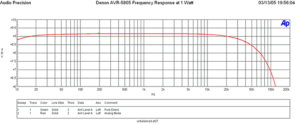
Frequency Response at 1 watt was ruler flat within the audio band with a -3db point of about 125kHz.
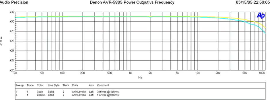
Whether driving at 1watt or full rated power, frequency response uniformity of the AVR-5805 amp section was exceptional.

When driving the AVR-5805 at around 157wpc into 8 ohms, I ran a frequency response sweep against a 4 ohm load under the same test conditions where it happily delivered exactly twice the power (315wpc).
This indicated two things:
- The Denon amp had a low enough output impedance and enough power supply reserves to act like an ideal voltage source to double down its power delivery as the load impedance halved.
- While doing so, it maintained excellent frequency response uniformity (falling well within our preferred +-.25dB deviation window) indicating excellent gain product bandwidth and lack of slew induced distortion when driven hard.
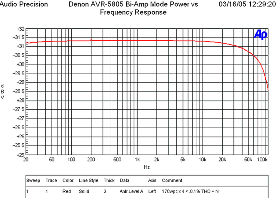
Since the AVR-5805 sported a cool "Bi-Amp" mode, I wanted to see if it could deliver the goods in this scenario. I configured the AVR-5805 front channels for biamping and tested for maximum unclipped power.
Editorial Note on Power Measurements
We do NOT hold the line voltage constant like some publications do, as we believe in testing for real world conditions. Consumers typically don't have the luxury of stabilizing their power and/or providing enough wall current to source max power with all channels driven (a very unrealistic test condition and a very idealistic test load we might add). In any event, I was able to achieve a 170wpc at 0.1% THD with four channels driven but noted that my dedicated 20A line sagged from 124V to 119V under this test. In reality, the AVR-5805 probably could have delivered an extra 10wpc or so in a more sterile lab environment. This test certainly proved the AVR-5805 was a true powerhouse. For the fun of it I reran this test for five channels driven and was able to achieve about 145wpc at 0.1% distortion but again watched the line voltage sag down to 110V during this test. Thus again, this amp is certainly able to deliver the full capabilities of a 15A outlet and then some! Based on the amount of power reserves available in this receiver I would venture to say if you had a stabilized dedicated line to run this receiver, it could probably drive up to 7 channels simultaneously at full bandwidth unclipped at its rated 170wpc into 8 ohms assuming an internal fuse doesn't blown first. Before you actually declare your set-up can achieve this power, consider this: The efficiency of a typical class A/B amp, such as the ones found in this receiver, is around 35-40%. Let's assume 40% in this instance. In order to deliver 170wpc x 7, it would require: 170*7/.4 = 2975 watts! For a 120VAC system your line would be required to deliver 25 amps! Unless you are running 3 phase power, or convince the power company to run 6AWG romex and up the circuit breaker from a standard 15A to a hulking 25A, this simply isn't gonna happen (no, not even with name brand separates). Not to mention the fact that UL certified products such as this one are limited to 15A power consumption at the interface connector for safety reasons. Remember this next time your friend boasts about his dedicated 7CH 200wpc Class A/B amp which sports a single line cord connection.For more information on this, check out The All Channels Driven (ACD) Test Fallacy
In reality, the power supply and amp section of the AVR-5805 are not the limiting factors for maximum power delivery for all channels driven, the outlet and power receptacle are.
Food for thought for power freaks that think they will actually use this much power in all channels at the same time.
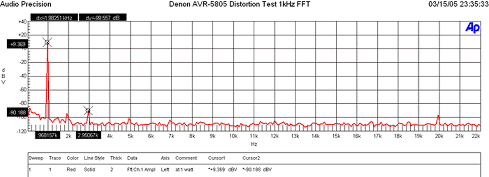
Distortion at 1 watt was practically nonexistent. A quick glance at the AVR-5805's distortion profile at 1 watt revealed excellent results (+9.369+90.188)dBv = 99.557dBv (about 5dB better than the Integra Research RDA-7.1 ) or 100*log(-99.557/20) = .001%.
Denon AVR-5805: Power Measurements Cont
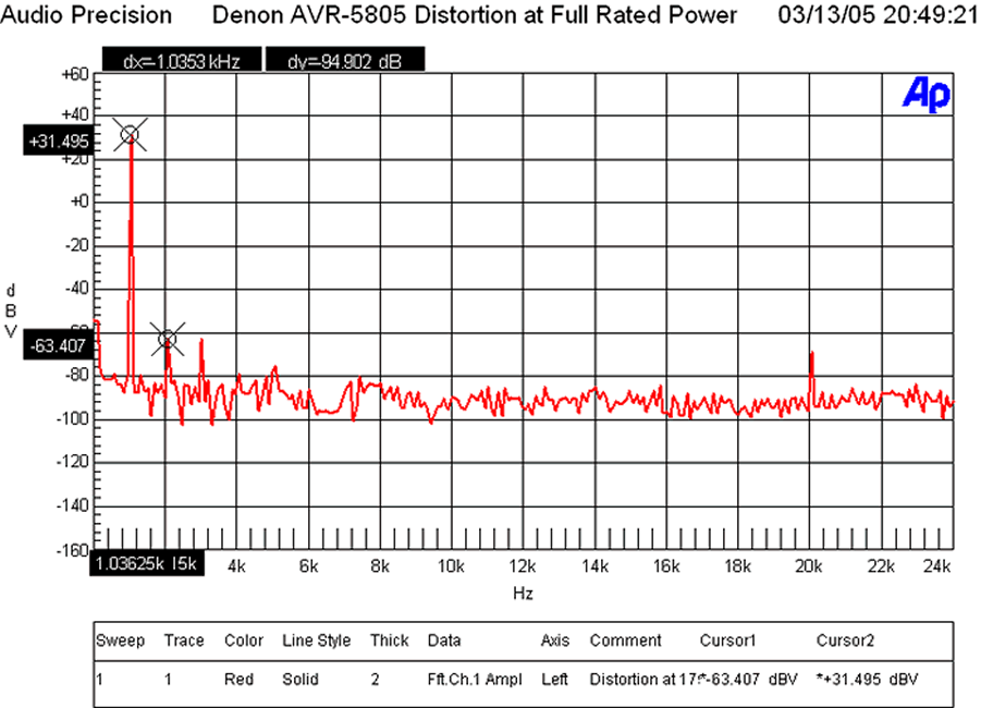
At 175wpc our FFT distortion analysis again revealed stellar results. (+31.495+63.407)dBv = 94.902dBv (almost 10dB better than the Integra Research RDA-7.1) or 100*alog(-94.902/20) = .002%
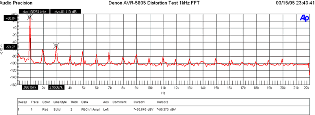
At 303wpc into 4 ohms, the AVR-5805 did commendably well, though you could see the onset of higher order harmonics kick in. The (30.84+50.27dBv)dBv = 81.1dBv (about 1.1dB better than the Integra Research RDA-7.1 ) or 100*log^-1(-81.1/20) = .009%
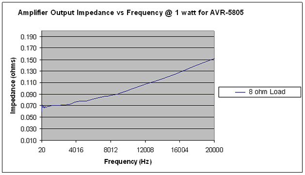
The output impedance of the AVR-5805 is commendably low for an amplifier with a single pair of very powerful and well designed power transistors per channel. By weight of comparison, it's about 2x that of the Integra Research RDA-7.1 that featured 8 complementary output devices per channel and subsequently measured two feet deep. I consider this the ultimate compromise in performance, space, and budgetary constraints. The reason we emphasis so much importance on minimizing amplifier output impedance is because the lower the impedance, the less chance of system frequency response variation when driving reactive loads such as speakers and/or many exotic cables.
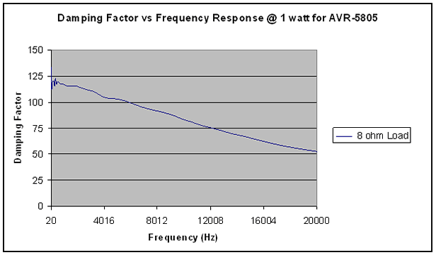
An amplifier that exhibits low output impedance will also exhibit excellent damping factor. The AVR-5805 maintained an impressive damping factor of over 50 throughout the entire audio bandwidth. These type of measurements are uncharacteristic of tube amplifiers or budget receivers which is where they usually fall apart when attempting to drive low impedance, inefficient speaker loads. This design is a far departure from that design characteristic.
At full power we see the AVR-5805 maintains its composure into an 8 ohm load with a meager increase in output resistance of 10mohms and almost identical damping factor. An excellent achievement!
The true test is how well an amp will hold up into low impedance loads. Ideally and amplifier should act like an ideal voltage source meaning power will double as load impedance halves since output voltage will remain constant. In order to do this, the amplifier output impedance must maintain a low enough level to not be the limiting factor.
As you can see, the output impedance is very similar to the 8 ohm full power test! Based on the principle of voltage divider, we should see about ½ the damping factor from our 8 ohm case.
No surprises there! This amp delivered the goods.
Denon AVR-5805: Suggestions and Conclusions
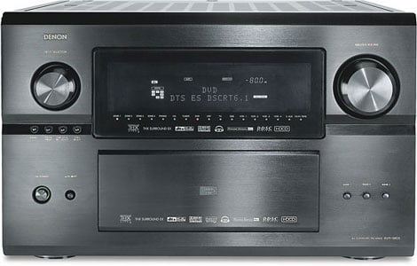 Let's face it, nothing is perfect, though the AVR-5805 comes pretty darn close. In fact, out of all of the products I have ever reviewed, this one was the most difficult to write a laundry list for. After some thinking, however, I came up with a short list of areas in which I would like to see updates and/or improvements:
- Analog Video Upconversion to HDMI with OSD support (firmware upgrade coming soon).
- More representative graphical depiction of the Audyssey results (instead of the cheesy one octave bar graph readouts, and these should include the subwoofer channel).
- Provide mute during search and acquire on PCM DTS bitstreams from DTS CD's.
Recommendations
The Denon AVR-5805 is not for everyone. Serious home theater aficionados and music lovers are what this product was bred for. Unless you are an experienced home theater hobbyist, we strongly encourage having your dealer and/or certified custom installer set-up and integrate this product into your system. This is why Denon doesn't ship the receiver with the calibration mic like they do with all of their other products featuring auto setup. Care must be followed, as per the guidelines in this review, when setting up Audyssey to achieve the maximum benefits. Denon recognizes this product requires a knowledgeable Installer to reach its maximum potential. Their dedication is most obvious by the existence of their extensive mandatory eight hour training course for authorized dealers and installers.
This receiver is enormous at almost a foot in height, but redeems itself by maintaining a manageable depth of about 20 inches. Most standard home theater racks will accommodate the width and length of this product, but you may find the need to remove a shelf or two above this receiver to provide plenty of air flow. Unlike the AVR-5803 that ran relatively cool under all but the most extreme conditions, the AVR-5805 runs hot, even during idle. Considering it has double the power supply, three more power amps, over 3 times the amount of components, and more than double the processing power of its predecessor, this should come as no surprise. My advice is to provide plenty of open ventilation (at least 6 inches above and either an open front or back for steady airflow.
Conclusion
The Denon AVR-5805 is truly the most innovative product of the year and certainly (currently) the most advanced receiver or processor for that matter on the market. I can think of no other product that better exemplifies the bleeding edge in technology, fit and function than the AVR-5805. At first glance the $6k price tag may seem a bit steep until you consider this single box solution essentially takes the place of three with so many added goodies (i.e. Audyssey, HDMI, I/P scaling, etc) that no separates solutions currently offer. Throw in state of the art processing, and the ultimate in bass management flexibility, along with the most robust amplifier section we have ever seen in a receiver, and this product clearly reins supreme. I cannot convey in words how much enjoyment this product has added to both my music listening and movie watching experiences. And all this despite that fact that I have yet to tap into all of its capabilities. With that in mind, it is our intention to make the AVR-5805 one of our mainstay processor platforms in Staff Reference System #1 . I feel there is so much more potential to unleash in this platform and I look forward to supporting hardware and firmware upgrades (especially analog video upconversion to HDMI) so long as Denon supplies them. Towards the end of the year when my new home theater room is completed, I will consider integrating a Denon AVR-5805 into my primary reference system. In this configuration it would also be used to drive a full fledged second zone 5.1 surround system in a master bedroom with distributed audio in other rooms. This would certainly allow me to see and hear first hand the full capabilities of this masterful machine.
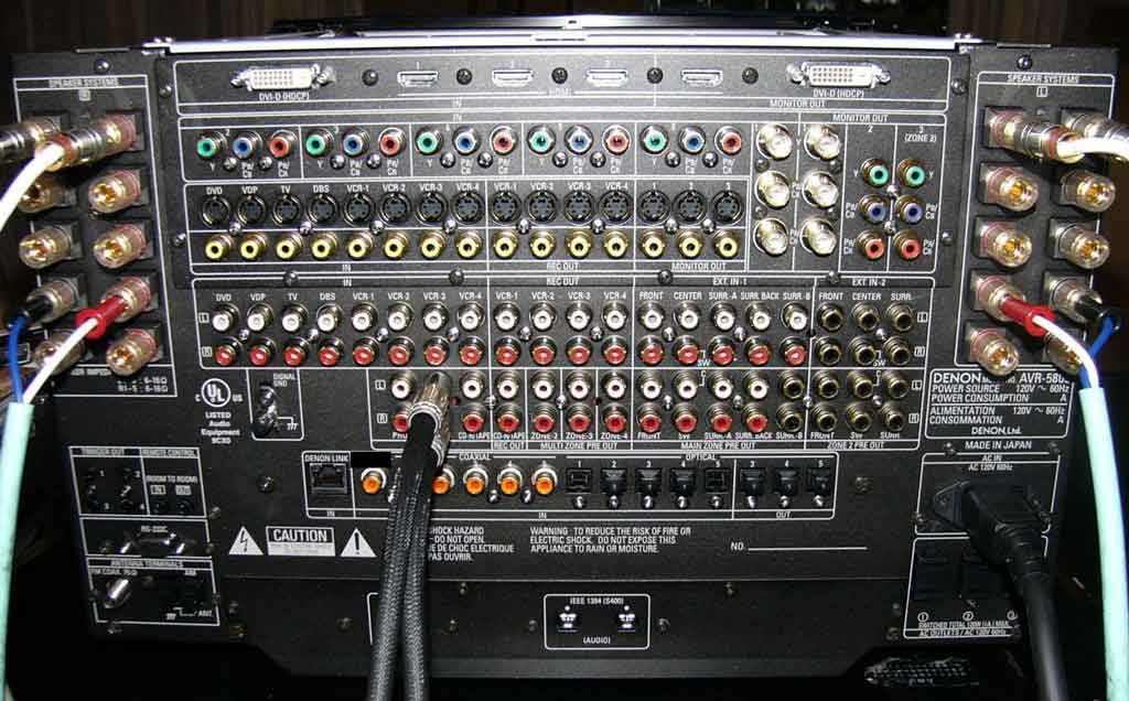
Denon AVR-5805 Backpanel connections
Don 't let your snobby audiophile friends or forum cult hobbyists dissuade you from purchasing a receiver. This is truly a state of the art and, equally important, an audiophile product that if properly set up will rival the performance of most separates solutions regardless of price. It is a highly flexible piece that can fit the bill for almost any conceivable home theater or audio application. Its upgradeability path ensures years of enjoyment and manufacturers support to keep it current for the next big wave of technological progress. The Denon AVR-5805 truly is the ultimate one box separates solution that represents a quantum leap in technological achievement which will surely birth a new trend in home theater with respect to home system integration and room correction.
The Score Card
The scoring below is based on each piece of equipment doing the duty it is designed for. The numbers are weighed heavily with respect to the individual cost of each unit, thus giving a rating roughly equal to:
Performance × Price Factor/Value = Rating
Audioholics.com note: The ratings indicated below are based on subjective listening and objective testing of the product in question. The rating scale is based on performance/value ratio. If you notice better performing products in future reviews that have lower numbers in certain areas, be aware that the value factor is most likely the culprit. Other Audioholics reviewers may rate products solely based on performance, and each reviewer has his/her own system for ratings.
Audioholics Rating Scale
 — Excellent
- — Very Good
- — Good
- — Fair
- — Poor
| Metric | Rating |
|---|---|
| Frequency Response Linearity | |
| SNR | |
| Output Impedance | |
| Measured Power (8-ohms) | |
| Measured Power (4-ohms) | |
| Multi-channel Audio Performance | |
| Two-channel Audio Performance | |
| Build Quality | |
| Fit and Finish | |
| Ease of Setup | |
| Features | |
| Remote Control | |
| Performance | |
| Value |
Gene manages this organization, establishes relations with manufacturers and keeps Audioholics a well oiled machine. His goal is to educate about home theater and develop more standards in the industry to eliminate consumer confusion clouded by industry snake oil.
View full profile