
Denon AVP-A1HDCI AV Processor Review
- Product Name: AVP-A1HDCI 12CH Home Theater Processor
- Manufacturer: Denon Electronics
- Performance Rating:

- Value Rating:

- Review Date: June 16, 2008 23:50
- MSRP: $ 7,500
|
|
Pros
- Unprecedented benchmark level of performance and refinement
- Virtually unlimited configurability options
- Lacks nothing in features to minimize obsolescence
Cons
- Audyssey and other processes can limit max volume
- Complex setup
- Expensive
Denon AVP-A1HDCI Introduction
 Maybe you should wait another 3-4 years until Denon
comes out with a replacement to the AVP-A1HDCI
A/V processor / preamp. While you’re at it, you
might as well wait on purchasing a new car.
By then, the car industry would be releasing an affordable sports sedan
that gets 100mpg running on plant algae with a 0-60 time in under 5 seconds and
Denon would have added yet another must have feature not currently found on
this model. After all, this bad boy won’t
network with your “smart” refrigerator or stove top despite it has an Ethernet port
and is WiFi capable, nor will it run on solar power as going “green” hasn’t hit
the A/V marketplace yet as it’s barely reached out to the car industry. You can wait, and wait or be content with the
fact that the AVP-A1HDCI will
decode and process every current A/V format unadulterated and leave room for
future ones via external inputs and/or firmware upgrade options to ensure what
you buy today won’t double as an expensive door stop tomorrow or the days that
follow shortly thereafter. As for the fuel
efficient sports car….don’t hold your breath….
Maybe you should wait another 3-4 years until Denon
comes out with a replacement to the AVP-A1HDCI
A/V processor / preamp. While you’re at it, you
might as well wait on purchasing a new car.
By then, the car industry would be releasing an affordable sports sedan
that gets 100mpg running on plant algae with a 0-60 time in under 5 seconds and
Denon would have added yet another must have feature not currently found on
this model. After all, this bad boy won’t
network with your “smart” refrigerator or stove top despite it has an Ethernet port
and is WiFi capable, nor will it run on solar power as going “green” hasn’t hit
the A/V marketplace yet as it’s barely reached out to the car industry. You can wait, and wait or be content with the
fact that the AVP-A1HDCI will
decode and process every current A/V format unadulterated and leave room for
future ones via external inputs and/or firmware upgrade options to ensure what
you buy today won’t double as an expensive door stop tomorrow or the days that
follow shortly thereafter. As for the fuel
efficient sports car….don’t hold your breath….
Denon took a hiatus from making dedicated pre/pros for longer than I can remember. Instead, their focus was on bringing to market some of the most feature packed performance receivers in efforts to become one of the dominant players in the receiver market. Their efforts have paid off and they proved they could dominate market share at all price levels and even push the envelope with their introduction of the $6k AVR-5805 multi functional “super receiver” which to date, in my opinion, is still one of the best performing A/V receivers ever built! The AVR-5805 had a good run for 4+ years but has since than been replaced by a scaled back successor – the AVR-5308CI. While the AVR-5308CI has virtually all of the same features found on this processor, it lacks the balanced circuitry design, class A audio drivers and a host of other component upgrades (some of which I found measurable differences during my preamp testing of the two units). Considering the AVR-5308CI sells for about $2k less than this preamp and has nine respectable built-in power amplifiers, I’d say it makes it quite a bargain.
Denon has aimed its sights higher with the introduction of their AVP-A1HDCI (A/V pre/pro) and POA-A1HDCI (10 channel power amp) separates solution which goes up against the likes of Krell, Lexicon, Classe, etc. These are not value products, but instead statement pieces to show off Denon’s engineering prowess and legitimize their brand into the high end market segment. The question remains however, will this separates solution deliver the goods and carry enough prestige to justify the $14k price tag? Read on to find out….
Denon AVP-A1HDCI Design Overview
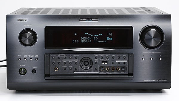
 Weighing in at nearly 60lbs, the AVP-A1HDCI is more massive than most flagship
receivers, including their very own AVR-5308CI. Typically when I pop the cover off a so
called “high end” processor, I see a lot of empty space. This is not the case with the AVP-A1HDCI.
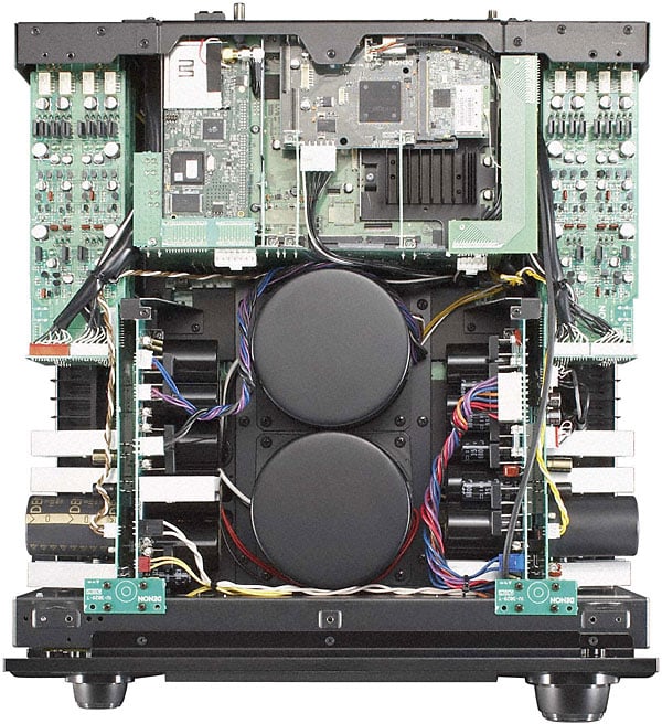
This baby is packed full of
components and its packed in there
so snuggly, that I’d venture to say Denon could have went with a larger chassis
to give it an even more “audiophile”
appeal to it. The AVP-A1HDCI actually uses the same casing from the
venerable AVR-5803 receiver but
sports all new electronics including two large shielded torroid
transformers. The AVP-A1HDCI utilizes a traditional linear power
supply and there are tons of high quality power supply capacitors stacked to the sides of the chassis to ensure clean
stable power is never an issue. The
finned heatsink near the top of the chassis and below the WiFi card is utilized
for the Realta / HQV processor
Weighing in at nearly 60lbs, the AVP-A1HDCI is more massive than most flagship
receivers, including their very own AVR-5308CI. Typically when I pop the cover off a so
called “high end” processor, I see a lot of empty space. This is not the case with the AVP-A1HDCI.
This baby is packed full of
components and its packed in there
so snuggly, that I’d venture to say Denon could have went with a larger chassis
to give it an even more “audiophile”
appeal to it. The AVP-A1HDCI actually uses the same casing from the
venerable AVR-5803 receiver but
sports all new electronics including two large shielded torroid
transformers. The AVP-A1HDCI utilizes a traditional linear power
supply and there are tons of high quality power supply capacitors stacked to the sides of the chassis to ensure clean
stable power is never an issue. The
finned heatsink near the top of the chassis and below the WiFi card is utilized
for the Realta / HQV processor
Denon boasts the AVP-A1HDCI is the world’s ONLY fully balanced processor from input to output (see left pic above). This can be seen by the large array of balanced outputs (9 for the mains and center/surrounds, and 3 for independent subwoofer outputs). You can configure for two different pairs of surround speakers for optimized positioning for music vs movies or run two pairs of side or back channels for larger theater installs to increase coverage. Denon doesn’t just stop with balanced outputs, they also sport two balanced inputs via the CD input and follow the balanced topology from input to output of the entire product. The advantages of fully balanced circuit designs include significant reduction in distortion and noise / RFI/EMI pickup. The only disadvantage is cost and complexity in circuit design as you need double the components and occupy more internal real estate. Denon utilizes a direct mechanical grounding scheme with independent transformers and power supplies for each block as can be seen in the above right pic. The preamp drivers are all high current pure class A for the best fidelity and signal drive possible. Like with past flagship Denon products such as the AVR-5805CI, the AVP-A1HDCI uses the very best Burr Brown PCM-1796 dual differential DAC’s (four per channel), coupled with Denon’s own proprietary DDSC-HD digital audio technology and Advanced AL24 processing for the highest linearity and lowest noise floor possible.
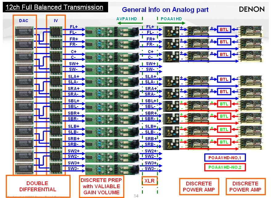
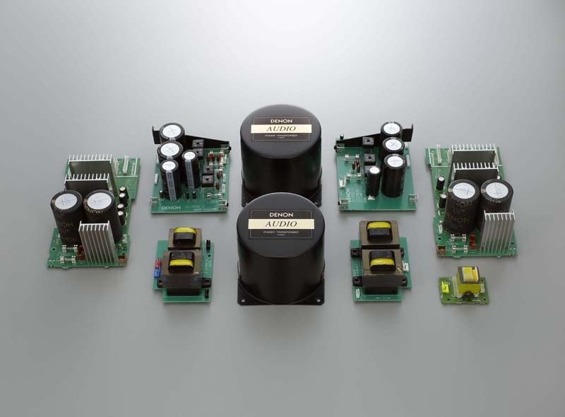
Denon AVP-A1HDCI Architecture Block Diagram (left pic); power supply parts (right pic)
Video Processing
 On the video side, Denon uses Silicon Optix Realta HQV
processing and scaling with built in multi-cadence detection for accurate i/p
conversion when standard interlaced video is viewed on progressive scan
displays. The Realta sxT2 HQV 10-bit processor converts standard interlaced
signals into progressive scan signals in order to eliminate the stair-casing
effect that conventional up-converters can introduce to diagonal edges. In
addition, this unit's Full 10-bit video processor can pass a 1080p/24fps signal
through its HDMI input/output and supports Deep Color up to 36-bit and xvYCC broader
color spacing via HDMI while also supporting full conversion of all analog signal types including composite
video, S-Video, and component video to HDMI up to 1080p. If you were to put all of the video features
and processing the AVP-A1HDCI has
on board into a stand alone box, it would easily sell for $2500 or more. Consider it a bargain that Denon lumps this
technology with independent configurability per input into this processor.
On the video side, Denon uses Silicon Optix Realta HQV
processing and scaling with built in multi-cadence detection for accurate i/p
conversion when standard interlaced video is viewed on progressive scan
displays. The Realta sxT2 HQV 10-bit processor converts standard interlaced
signals into progressive scan signals in order to eliminate the stair-casing
effect that conventional up-converters can introduce to diagonal edges. In
addition, this unit's Full 10-bit video processor can pass a 1080p/24fps signal
through its HDMI input/output and supports Deep Color up to 36-bit and xvYCC broader
color spacing via HDMI while also supporting full conversion of all analog signal types including composite
video, S-Video, and component video to HDMI up to 1080p. If you were to put all of the video features
and processing the AVP-A1HDCI has
on board into a stand alone box, it would easily sell for $2500 or more. Consider it a bargain that Denon lumps this
technology with independent configurability per input into this processor.
Audyssey MultEQ XT & Dynamic EQ (DEQ)
The AVP-A1HDCI sports Audyssey MultEQ XT with eight-point auto setup and a new feature called Dynamic EQ. Unlike conventional loudness controls, Dynamic EQ is NOT based on the Fletcher & Munson curves. Instead it works in tandem with Audyssey equalization using proprietary methods for real-time calculations of differences between reference level and playback level curves to ensure proper tonal balance correction regardless of listening level. There are plans to upgrade AVP-A1HDCI with Audyssey Dynamic Volume and Pro Installer which would enable the installer to use Audyssey’s own calibration kit, boost measurement points from 8 to 32, and allow curve editing per channel. I will be reporting on my experiences with these upgrades later in the year when they become available assuming I still have the pre/pro at my disposal.
Network Streaming, Wifi, XM Radio, iPod and more
The Denon AVP-A1HDCI is packed with networking features typically found on media PC’s and unheard of in A/V receivers and processors only a couple of years ago. Not only does the AVP-A1HDCI sport an Ethernet port for a direct internet connection to handle firmware updates and audio streaming, but it can also connect wireless via a WiFi (802.11b/g) connection for even further flexibility. The AVP-A1HDCI defaults to the Ethernet connection once you plug the cable in and I found it a breeze to connect to my network whether wired or wirelessly.
As with most of the latest generation of upper echelon A/V receivers, the AVP-A1HDCI integrates XM Radio and iPod connectivity, but it also boasts the ability to do internet radio, Rhapsody and HD radio.
Internet Radio
Net Radio
is a free (for the time being) internet radio program that allows you to stream
stations off the internet to your receiver/processor.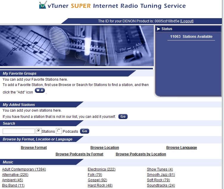
For Setup goto: http://www.radiodenon.com and follow the procedure below:
1. *Select
the “Net” input on the AVP-A1HDCI
2. Push the
"MENU" button.
3. Select the "MANUAL SETUP".
4. Select the "NETWORK SETUP".
5. Select the "Network Info".
6. Display Shows the MAC Address.
7. Enter
the MAC address online
* make sure
you don’t forget to do step 1, else the website won’t identify your product
even if you type in the MAC
address for it.
What’s really cool about Denon’s Net Radio, is you can program all of the stations you want online. The website breaks down over 11k available channels by location, genre and streaming quality. You can group stations which will automatically update on the AVP-A1HDCI once/day though my unit was updated almost instantly. Audio quality varies from 64kbps MP3 to 128kbps WMA even some AAC for jazz stations but those seemed mostly limited to 64kbps.
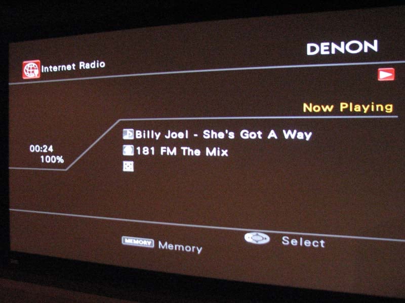
When you select the “Net” input, you are brought to an OSD (left image) where you can make your choice between Rhapsody, Internet Radio or Media Server. I selected Internet Radio and within minutes, I was chilling to tunes from stations all around the world. I found an all Beatles channels and also happened on some Billy Joel in the process. Too bad you can’t search by artist but perhaps they can add that feature in the future.
Rhapsody
Rhapsody is
a paid music broadcast system that gives you access to millions of song for a
$12.99 monthly access fee. There is
supposedly a free 30 day trial accessible to Denon users by signing on to: http://www.rhapsody.com/denon/signup
but I was unable to take advantage of it.
I even emailed them to see if I could get temporary access to this
service for my review but received no response.
Perhaps I will revisit this music service in a later review.
Music Server
The AVP-A1HDCI's Music Server function lets you stream
audio and still image files from your PC via Windows Media Player Network
Sharing Service or Windows Media Player 10 (or higher). To access iTunes library and playlists
you need to install TwonkyMedia software to your PC. Twonky Vision is a
software program needed to network and manage your iTunes database and can be downloaded
from www.twonkyvision.com for a one
time fee of $29.99.
Enhancing Sound Quality Through
“Restorer”
To ensure
the best fidelity possible, there are three proprietary DSP music enhancer
modes labeled as “Restorer 1, 2, 3” which attempt to improve the fidelity of
compressed music sources making them more palatable to listen to. This is a good feature to have and was
beneficial in usage, especially via Internet Radio and MP3 copied music. I tried them out and found modes 1 & 2 to
sound nearly identical whereas mode 3 labeled “HQ” seemed to over boost the
highs and seemed more appropriate on stations that were
severely lacking high frequency
response. You can even overlay PLIIx
Music Mode when using the “Restorer” sound enhancer which really adds further
intricacies to the music.
Multi Zone Audio – A Total Home Solution
The AVP-A1HDCI is armed to the teeth when it comes to audio and video support for up to three additional zones. Although the AVP-A1HDCI doesn’t do a second zone of 5.1 DD/DTS decoding (a feature only found on the AVR-5805 receiver) it does offer digital optical outputs for zones 2 and 4 to interface with additional A/V receivers and stream its sources to them for decoding and processing. Zones 2 and 3 offer stereo line-level audio outputs with volume, balance HPF option, and tone control where Zone 2 features composite, s-video and component video output and Zone 3 has composite video output. Zones 2 and 3 also boast conversion of optical or coaxial digital signals to analog audio output for 2nd and 3rd rooms (PCM signals only) so you don’t have to run additional analog audio cables from each source should you desire them to play on those two zones. Combine this with Denon’s music streaming capabilities, RS232 functionally for external control, and four high current (250mA / 12V) triggers assignable to zone, input source, surround mode, HDMI monitor, etc ensures that the AVP-A1HDCI can intelligently operate your entire home theater system and serve as the demarcation point for entire home A/V solution.
It’s good to know that when you’re buying a high end processor from Denon, you aren’t buying a hollow box with a lot of hot air in it like many esoteric companies tend to offer. This product is built like a tank and utilizes some of the very best analog and digital components the industry has to offer.
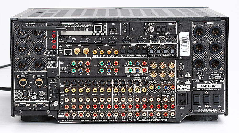
Back Panel View of the Denon AVP-A1HDCI
The AVP-A1HDCI rear end’s impressive stature would make even Jennifer Lopez envious. With every conceivable connection type supported including two BNC’s digital outputs, one set of BNC component video inputs and outputs, six HDMI inputs, two HDMI outputs, 12 balanced outputs and 2 balanced inputs; the AVP-A1’s got you covered with enough goesintas and goesoutas to serve even the most sophisticated home theater and multi zone audio installations.
Denon AVP-A1HDCI Basic System Setup & Configuration
Once you’ve made all of your connections, you need to get to work on properly setting up your AVP-A1HDCI to ensure maximum enjoyment. I recommend proceeding as follows to get the basics all setup so you’re up and running.
Step 1: Option Setup
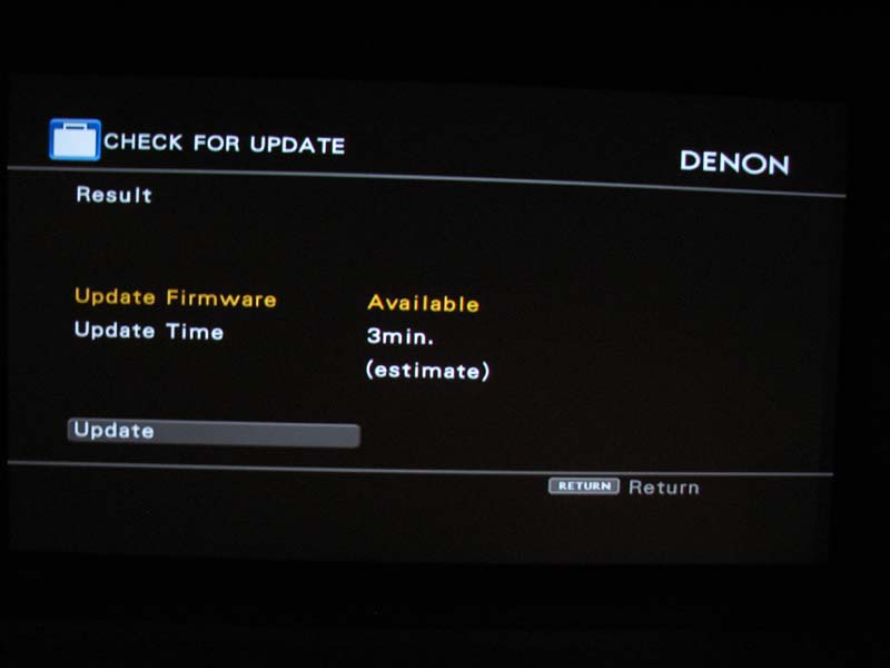 The first thing you’re going to want to do after
connecting up the AVP-A1HDCI to
your system is check for an update
in firmware via the Ethernet connection.
Do NOT use a wireless connection when updating firmware as you risk
really hosing up the processor should the connection be interrupted during the
upload process. To update the firmware
you simply enter the “Option Setup” area of the OSD and select “firmware update”. Depending on the extent of the upgrade, it
can take up to 1 hour to complete. When
I ran this function, my update was rather minor and only took 3 minutes. “Option Setup” also has an area to upgrade
your AVP-A1HDCI with new features
which I am hopeful Denon will actually support and not just have as a selling
point like so many other manufacturers have done in the past when boasting
upgradeability.
The first thing you’re going to want to do after
connecting up the AVP-A1HDCI to
your system is check for an update
in firmware via the Ethernet connection.
Do NOT use a wireless connection when updating firmware as you risk
really hosing up the processor should the connection be interrupted during the
upload process. To update the firmware
you simply enter the “Option Setup” area of the OSD and select “firmware update”. Depending on the extent of the upgrade, it
can take up to 1 hour to complete. When
I ran this function, my update was rather minor and only took 3 minutes. “Option Setup” also has an area to upgrade
your AVP-A1HDCI with new features
which I am hopeful Denon will actually support and not just have as a selling
point like so many other manufacturers have done in the past when boasting
upgradeability.
Next you will want configure your preamp out assignments in the “Option Setup” menu. I left the assignments by default and simply selected XLR for all connection types since I ran all Impact Acoustics Sonicwave XLR cables between my AVP-A1HDCI and POA-A1HDCI 10 channel power amplifier. In the rare instances when you connect up an amplifier with reverse polarity on its inputs, Denon provides the option to reverse the polarity on any of the preamp output assignments.
Step 2: Auto Setup and Speaker Configuration
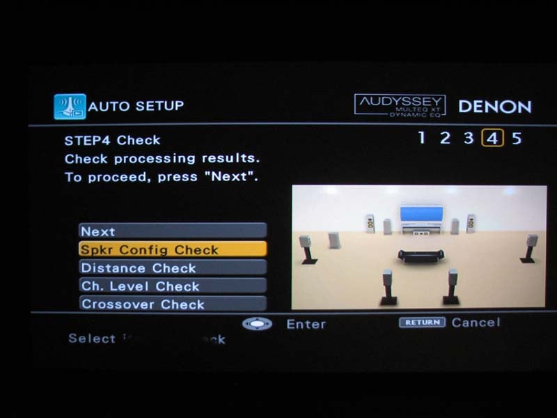 Even if
you’re not a fan of auto EQ’s, I still recommend running auto setup, if for
nothing more than accurately configuring and identifying your channels, level
trims and delays for all of your speakers and subwoofer(s). Since Audyssey utilizes up to 8 point room
correction, I suggest starting with the primary listening seat for the first
measurement, and then repositioning the mic for the other major seats in your
theater room. I do recommend closely
grouping multiple mic positions in the two most important seats in your theater
room so Audyssey weighs those positions more heavily and thus biases the
calibration in favor of those money seats.
Make sure your room is as quiet as possible and I encourage you to sweat
it out and turn off any ceiling fans and HVAC during the calibration
process. It’s usually best to place the
mic around ear seated height for all of your calibrations.
Even if
you’re not a fan of auto EQ’s, I still recommend running auto setup, if for
nothing more than accurately configuring and identifying your channels, level
trims and delays for all of your speakers and subwoofer(s). Since Audyssey utilizes up to 8 point room
correction, I suggest starting with the primary listening seat for the first
measurement, and then repositioning the mic for the other major seats in your
theater room. I do recommend closely
grouping multiple mic positions in the two most important seats in your theater
room so Audyssey weighs those positions more heavily and thus biases the
calibration in favor of those money seats.
Make sure your room is as quiet as possible and I encourage you to sweat
it out and turn off any ceiling fans and HVAC during the calibration
process. It’s usually best to place the
mic around ear seated height for all of your calibrations.
Unfortunately, ever since the new line of Denon receivers switched over from TI chipsets to the Analog Devices (ADI) ones, Audyssey takes longer (30 seconds) between measurements since the ADI chipsets likely have less available onboard memory. As a result it takes around 30 minutes to do a full eight point calibration so I urge patience during this process or use less calibration points at the expense of less calibration accuracy..
Step 3: Manual Calibration & Bass Management
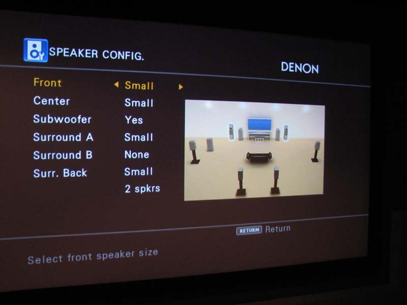 After auto setup completes, it’s time to fine tune your
results. I tend to find most auto setup
systems will set any speaker placed near a boundary to “large” regardless of
its bass output capabilities. This was
the case with my back surround speakers.
Thus I went into the bass management and reconfigured those speakers to
small. I then also corrected the
crossover settings for the center and back
channels to be more appropriate for my setup.
After auto setup completes, it’s time to fine tune your
results. I tend to find most auto setup
systems will set any speaker placed near a boundary to “large” regardless of
its bass output capabilities. This was
the case with my back surround speakers.
Thus I went into the bass management and reconfigured those speakers to
small. I then also corrected the
crossover settings for the center and back
channels to be more appropriate for my setup.
Level trims were about right, but considering my theater room has two rows of seating, I like to make a compromise for both and calibrate my levels between the two rows. Thus I used my SPL meter and tweaked down the center and surround channels a bit. Delay settings were pretty much spot on and I was pleased to see Audyssey nailed the subwoofer distance correct for all of my subs. To date, Audyssey is the only system I’ve found to consistently do this.
The Denon AVP-A1HDCI has some of the most comprehensive bass management facilities I’ve ever seen in a processor. It has three independent balanced and unbalanced subwoofer outputs which allows an end user to connect up to 6 subwoofers in their system without using a single y-splitter.
The configuration modes include: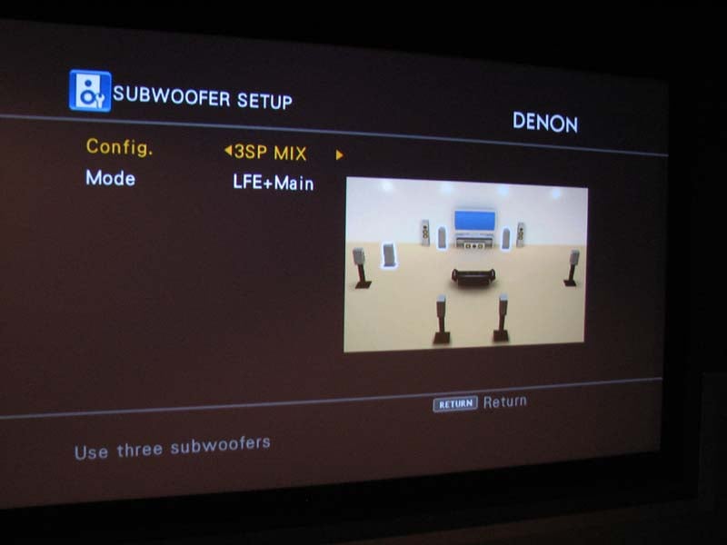
-
*1SP – assigned to SW1
-
*2SP L/R – stereo split + LFE to both, assigned to SW1 and SW2
-
*2SP Mix – mono split + LFE assigned to SW1 and SW2
-
3SP L/R/LFE – stereo split to SW1 and SW2 + LFE only to SW3
-
3SP Mix - mono split + LFE assigned to SW1 and SW2
* you can also connect a tactile transducer assigned to SW3 which outputs only LFE info when using these configuration modes
I am pleased to see Denon finally offer a 3SP Mix mode as their previous flagship receiver – the AVR-5805CI only sent LFE signal to the third subwoofer which doesn’t allow the installer to take advantage of all subs playing the exact same content for modal averaging. As it stands now, if you use “3SP L/R/LFE” to achieve stereo bass from the front SW1 and SW2 subs, the SW3 sub will be inactive until it receives LFE info rendering it useless for 2CH stereo sources. Thus I recommend using “3SP Mix” mode if you’re running a three subwoofer setup. In the future, I’d love to see Denon offer a “3SP L/R/LFE Super” mode that also sends LFE to the L/R subs while copying the bass from the main channels to SW3 but that is wishful thinking for now.
Just like all Audyssey enabled Denon A/V receivers, the AVP-A1HDCI offers independent crossover settings per speaker group from a selectable range of 40-250Hz. As with all multiple crossover processors, I recommend not varying each speaker group more than 20Hz as the bass from the speaker group set higher than the subwoofer crossover will not recombine to the subwoofer channel when listening to two channel sources in post processing modes like PLIIx Music or DTS Neo, etc.
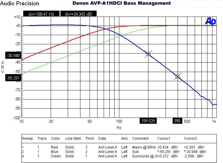
Denon AVP-A1HDCI Bass Management Measurement
The crossovers worked as expected
for a THX Ultra2 certified
receiver as indicated
 by the 12dB/oct High Pass Filter (HPF) slopes on speakers set small and
24dB/oct Low Pass Filter (LPF) slopes on the subwoofer output which I measured
with my Audio
Precision SYS 2722 Audio Analyzer. Channel
trims have .5dB incremental adjustments and delay settings have .1ft
resolution. This is about the best you
can get and it doesn’t surprise me Denon offers such a high level of precision
here, especially since their products were some of the first to incorporate
this level of adjustability. Oddly I had
to set the subwoofer outputs to +7dB for unity gain with any of the main
channels set to 0dB. I am not sure why
this was the case, but as you will see in my measurements, the AVP-A1HDCI has more than enough signal drive to
compensate if needed.The AVP-A1HDCI
would not allow me to set the main channels to “small” if I selected no
subwoofer which is how all processors should function to ensure the end user
doesn’t accidentally lose bass information from the main channels when not
using a dedicated subwoofer.
by the 12dB/oct High Pass Filter (HPF) slopes on speakers set small and
24dB/oct Low Pass Filter (LPF) slopes on the subwoofer output which I measured
with my Audio
Precision SYS 2722 Audio Analyzer. Channel
trims have .5dB incremental adjustments and delay settings have .1ft
resolution. This is about the best you
can get and it doesn’t surprise me Denon offers such a high level of precision
here, especially since their products were some of the first to incorporate
this level of adjustability. Oddly I had
to set the subwoofer outputs to +7dB for unity gain with any of the main
channels set to 0dB. I am not sure why
this was the case, but as you will see in my measurements, the AVP-A1HDCI has more than enough signal drive to
compensate if needed.The AVP-A1HDCI
would not allow me to set the main channels to “small” if I selected no
subwoofer which is how all processors should function to ensure the end user
doesn’t accidentally lose bass information from the main channels when not
using a dedicated subwoofer.
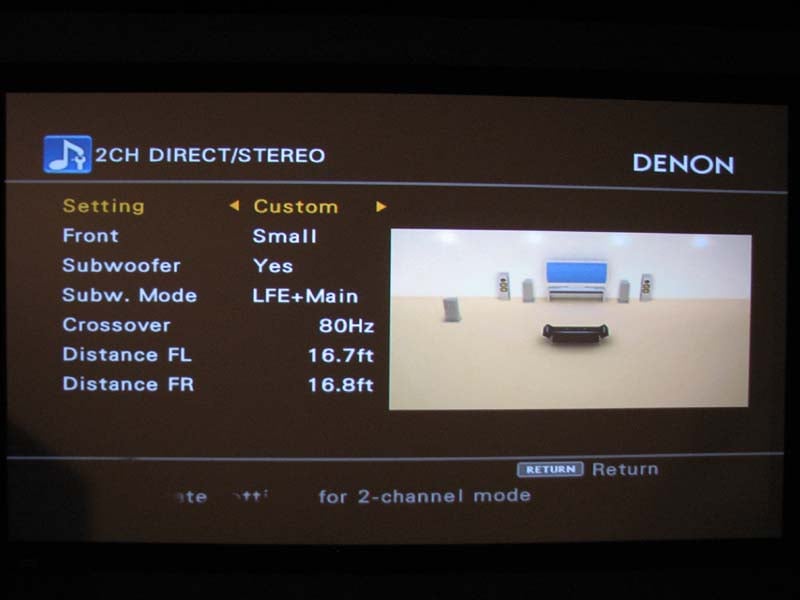
Don’t forget to configure to configure “2CH Direct/Stereo” mode to ensure you have proper bass management and channel distances configured, especially since distance settings for the main L/R speakers don’t copy over from the global settings yet oddly the subwoofer distances appear to. This is perhaps a firmware glitch but not a biggie as long as you are mindful of it. In order to achieve subwoofer output in “pure direct” mode, you must configure the bass management to “LFE + Main” regardless of speaker size chosen. I was glad to see this as an option since the AVR-5805 didn’t provision for subwoofer out in “pure direct” mode like their previous generation receivers did. Thus now you can have the best of both worlds of unadulterated signals to your main channels with simultaneous subwoofer output. The AVP-A1HDCI even allows for a +5, +10, +15dB boost for the subwoofer via the external multi channel inputs which is extremely useful to compensate for subwoofer level differences inherent in DVD-A/SACD players when using the analog outputs. As you can see, Denon offers every conceivable bass management option except for altering filter slopes but in my book it’s still the most comprehensive I’ve reviewed to date.
It’s important to note that the AVP-A1HDCI preamplifier has what Denon refers to as “personal memorization function” which automatically memorizes the surround modes and input modes selected for the different input sources. So if you normally run PLIIx Music mode for your CD player and Cinema mode for your DVD player, it will default to those modes upon toggling the respective input. Basically when the input source is switched, the modes set for that source last time it was used are automatically recalled. The surround parameters, tone control settings, and playback level balance for the different output channels are memorized for each surround mode. As a bonus, you can even do on the fly channel trim adjustments via the remote control. This is one of the many reasons why Denon AVR’s rank among my favorite in the industry.
Step 4: Input Configuration
Audio setup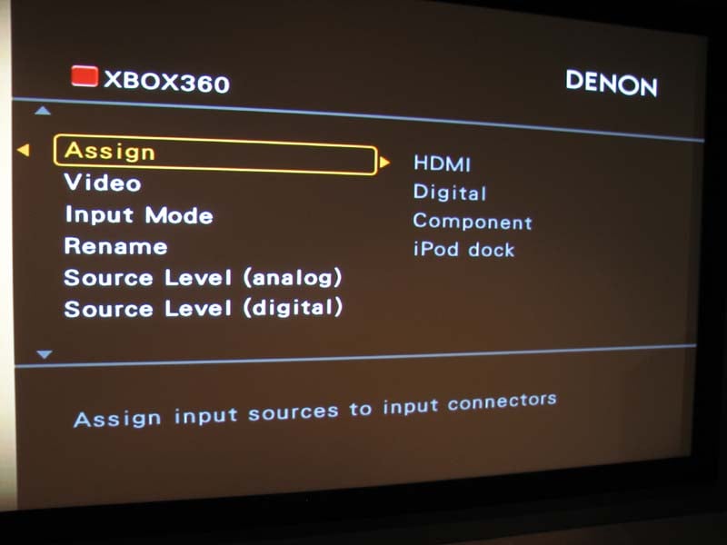 Once you’ve got your speakers calibrated, its time to
get your sources working correctly.
While the inputs are defaulted to their prescribed names on the back panel, it’s a good idea to check them, especially if you wish to reassign an HDMI
connector to a different source name. If
you’re using “D.Link”, make sure you set “I.Mode” on that specific input to
“digital” instead of “auto”, else it will default to the audio outputted by
HDMI from that source. This was a
problem for me with my DVD-5910CI
as it only outputs 2.0 audio via HDMI since my unit lacks the recent firmware
update to fix this.
Once you’ve got your speakers calibrated, its time to
get your sources working correctly.
While the inputs are defaulted to their prescribed names on the back panel, it’s a good idea to check them, especially if you wish to reassign an HDMI
connector to a different source name. If
you’re using “D.Link”, make sure you set “I.Mode” on that specific input to
“digital” instead of “auto”, else it will default to the audio outputted by
HDMI from that source. This was a
problem for me with my DVD-5910CI
as it only outputs 2.0 audio via HDMI since my unit lacks the recent firmware
update to fix this.
This is also the area where you can customize source level for analog and digital sources. Incidentally there is a feature called “Input Att.” With 0 and -6dB options but it oddly does absolutely nothing to attenuate analog or digital input signals.
Video Setup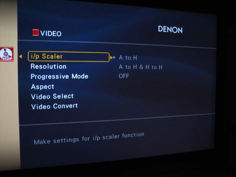 Setting up video is a bit tricky
since you have to access multiple menu locations but I suggest you first start
at the source and configure each input based upon the desired resolution,
aspect ratio and whether or not you want upscaling to be performed. The AVP-A1HDCI
allows upscaling to 1080p for all analog and digital video sources via an “A to
H’ which means analog to HDMI or “A to H and H to H” which allows analog or
HDMI signals to be upscaled to HDMI.
Setting up video is a bit tricky
since you have to access multiple menu locations but I suggest you first start
at the source and configure each input based upon the desired resolution,
aspect ratio and whether or not you want upscaling to be performed. The AVP-A1HDCI
allows upscaling to 1080p for all analog and digital video sources via an “A to
H’ which means analog to HDMI or “A to H and H to H” which allows analog or
HDMI signals to be upscaled to HDMI.
Now go to “Manual Setup > HDMI Setup” (see left pic below) and configure the color space “YCbCr or RGB”, and RGB range “normal or enhanced”. The operators manual is pretty much useless at giving recommendations here but most installs should be set for “YCbCr” and “normal”.
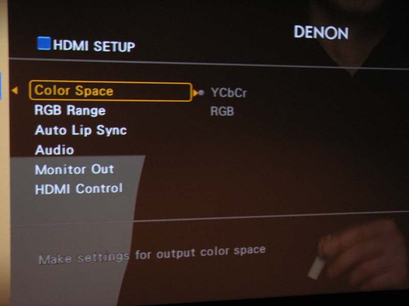
For more information about HDMI setup, read our article:
HDMI Enhanced Black Levels, xvYCC and RGB
Finally go to “Parameter > Picture Adjustment” (see above right pic) to tweak your contrast, brightness, hue and chroma levels. This is also where you can take advantage of the Realta DNR and Enhancer options. What is truly amazing is you have independent calibration settings for EVERY input! This is the first processor I’ve reviewed that allows for this and the first time I actually found these features useful for tweaking the calibration of my display to properly match each video source. To add icing to the cake, the AVP-A1HDCI provides two HDMI outputs which according to the manual will operate simultaneously and independently scale to the proper resolution of your displays.
When you’ve completed the setup of this processor, I highly recommend you store the settings in one of the three “Quick Select” memory banks incase you accidentally lose your configuration or one of your kids or friends that know less than they think mess it up.
Denon AVP-A1HDCI Video Tests & Audyssey Analysis
Denon has really reached the pinnacle of performance with the video processing capabilities of this processor. I loved the transparent OSD that overlays on the picture via HDMI. I’ve been waiting for this type of feature to come to market on pre/pro’s and best of all without compromise in picture quality. I ran a 480i signal out of my DVD-5910CI to the AVP-A1HDCI via HDMI and had the processor do the scaling and upconverting. I was pleased to note a perfect score (130) for HQV testing and full resolution via Avia test patterns. The AVP-A1HDCI was basically giving me indistinguishable results whether it or my DVD player did the processing and scaling. This isn’t too surprising considering both units have virtually identical video processing capabilities. Give the AVP-A1HDCI a quality interlaced signal and it will reward you with the very best picture quality the format is capable of delivering.
Audioholics/HQV Bench Testing Summary
Denon AVP-A1HDCI Benchmark Score: 130/130 (perfect score – it doesn’t get any better than this!)
| Test | Max Points | AVP-A1HDCI | Pass/Fail |
| Color Bar | 10 | 10 | Pass |
| Jaggies #1 | 5 | 5 | Pass |
| Jaggies #2 | 5 | 5 | Pass |
| Flag | 10 | 10 | Pass |
| Detail | 10 | 10 | Pass |
| Noise | 10 | 10 | Pass |
| Motion adaptive Noise Reduction | 10 | 10 | Pass |
| Film Detail | 10 | 10 | Pass |
| Cadence 2:2 Video | 5 | 5 | Pass |
| Cadence 2:2:2:4 DV Cam | 5 | 5 | Pass |
| Cadence 2:3:3:2 DV Cam | 5 | 5 | Pass |
| Cadence 3:2:3:2:2 Vari-speed | 5 | 5 | Pass |
| Cadence 5:5 Animation | 5 | 5 | Pass |
| Cadence 6:4 Animation | 5 | 5 | Pass |
| Cadence 8:7 animation | 5 | 5 | Pass |
| Cadence 3:2 24fps film | 5 | 5 | Pass |
| Scrolling Horizontal | 10 | 10 | Pass |
| Scrolling Rolling | 10 | 10 | Pass |
| Total Points | 130 | 130 |
|
*Source component was the Denon DVD-5910 set to 480i via HDMI output upscaled by the AVP-A1HDCI to 1080p and fed to the Epson Pro Cinema 1080UB Projector.
A real bonus to me was applying Realta processing to my Verizon FIOS service. I helped smooth out motion artifacts and extract the very best picture quality possible. Even some of the non high def channels looked deceivingly good. I was really digging Star Trek Enterprise, and the HD music channel in 1080p. Best of all I didn’t need to switch calibration settings on my projector since I dialed everything in on the AVP-A1HDCI via the input I was using for my FIOS service.
Audyssey Room Correction Analysis
I’ve reported Audyssey test results in countless reviews of A/V receivers that featured it in the past but I thought it would be prudent once again to illustrate how well it does on a flagship product while also covering Dynamic EQ.
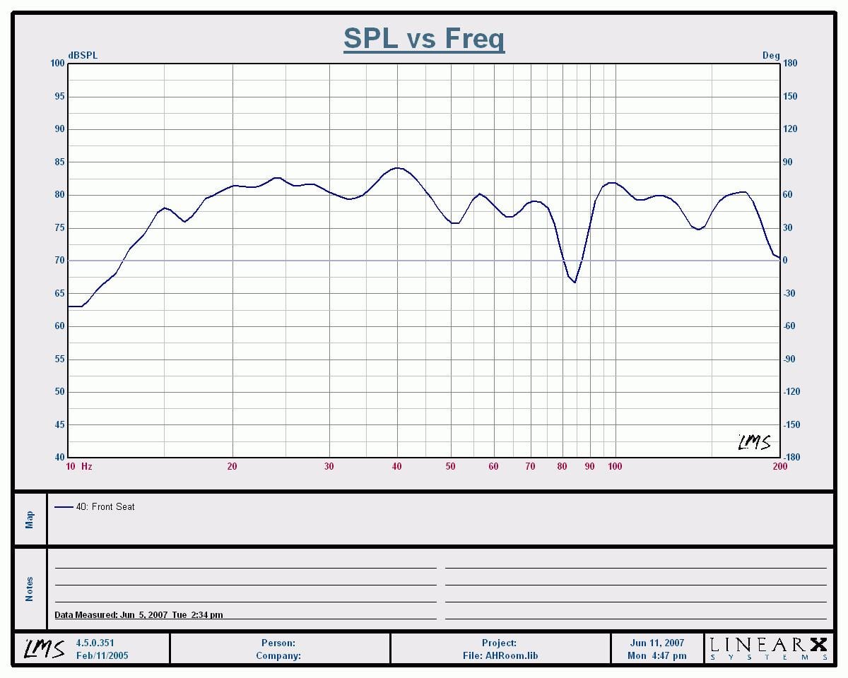
Calibration Results
(1/12th octave) of Denon AVP-A1HDCI (left) vs Audyssey MultEQ Pro
(Right)
Although I measured all seated positions in my theater room, I thought it would be best to focus on the money seat to compare how well Audyssey built into the AVP-A1HDCI faired against my stand alone Audyssey MultEQ Pro processor which sells for $2500. The calibration results are a combination of my two main channeIs playing simultaneously with all four of my subwoofers. I was able to achieve good post calibration results via the AVP-A1HDCI (+-6dB from 12Hz to 200Hz) but they weren’t quite as good as what I achieved with my Audyssey standalone box (nearly ruler flat sans the room suckout around 85Hz) running a special editor software Audyssey provided me so I could go in an customize the results. This isn’t surprising since the Audyssey standalone processor has double the resolution compared to its implementation in any A/V receiver or processor. I am hopeful once Denon releases the Audyssey Pro with receiver editor software for this processor, I can better dial in my calibration to nearly duplicate my original results without having to install another box between my pre/pro and amplifier. I will report back on this once the software becomes available.
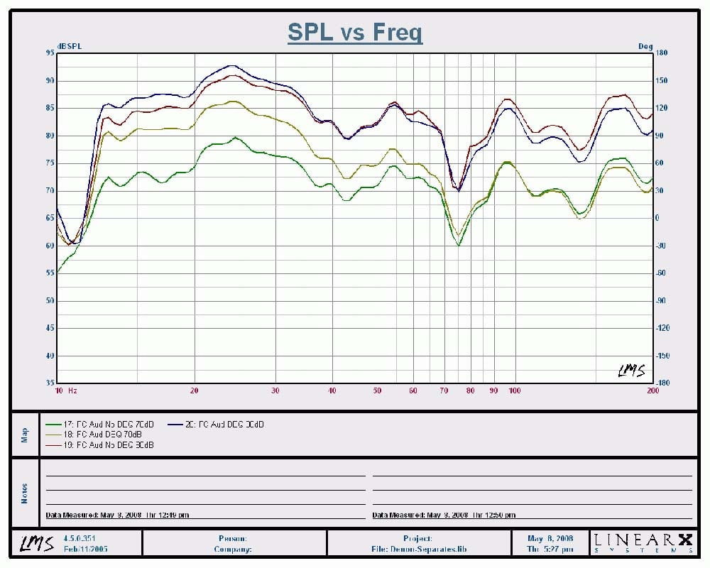
Dynamic EQ Frequency
Response Comparison @ Various Listening Levels
With Dynamic EQ (DEQ) engaged, you can see the bass boost below 70Hz of up to +10dB when listening at a 70dB average SPL. Once you start cranking the volume up, DEQ proportionally lowers the boost as you can see at the listening level of 80dB where the bass boost was a mere +3dB or so below 35Hz. If you look at the full range measurement I took of my front speakers, you will notice a modest boost of the high frequencies above10kHz with a slight recession in the 4-6kHz region. Perhaps the slight recession I measured in the midrange region partly explains why the vocals seemed get pushed back a bit in my Diana Krall listening tests I discuss later in the review.
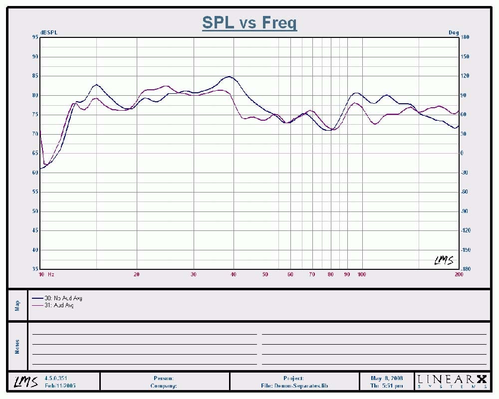
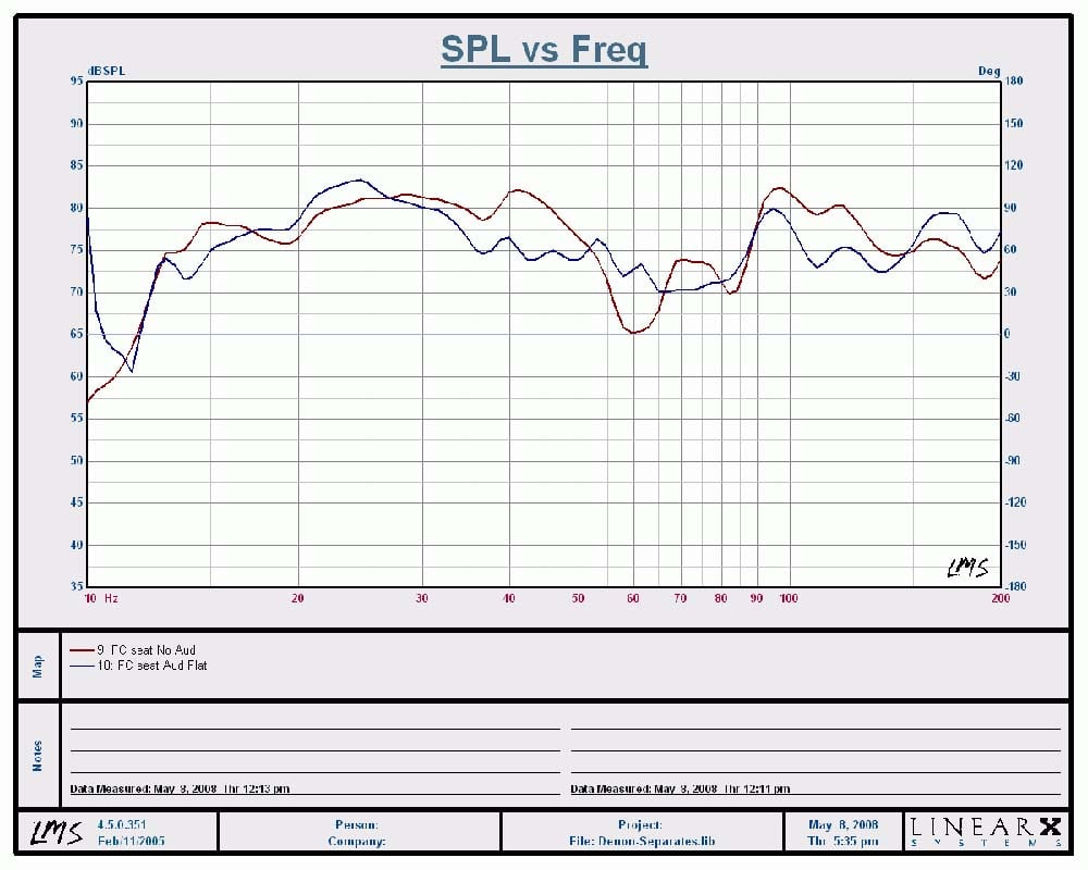
Overall Averaged Response Across Six listening
Positions
I applied an averaging algorithm to my LMS measurement system to chart out 6 listening positions with and without Audyssey calibration. With Audyssey engaged, it did smooth out the system bass response and I am certain once I have the curve editor feature, I can tune it in even better.
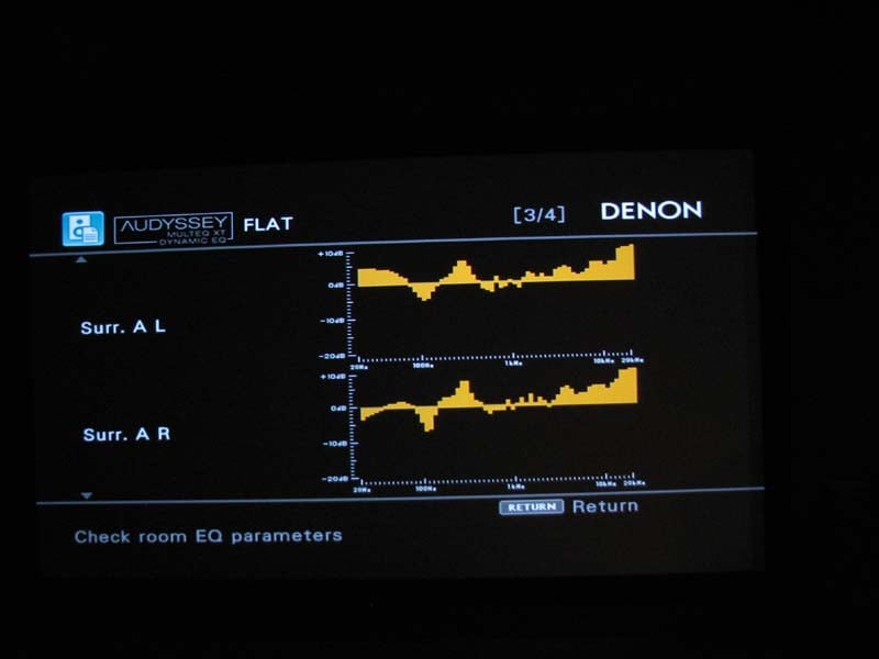
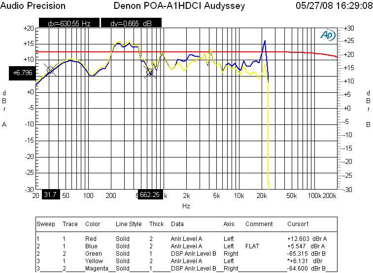
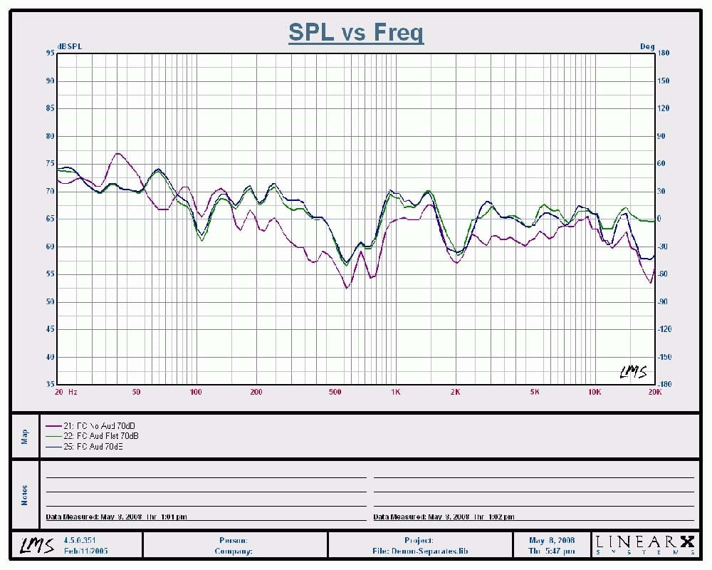
Audyssey Equalization
Results: Denon report (left pic); Actual measurement (right pic)
One thing I am not thrilled with is the fact that Audyssey does up to +9dB boosting. It’s usually NOT a good idea to boost levels since they are likely caused by room nulls and the end result is wasting power with little to no benefit for flattening frequency response. The Audyssey results show nearly +10dB boosts on my dipole/bipole surround channels and up to +5dB boosting on my mains. I also measured the preamp outputs of the main channels (above right pic) to quantify the results. The red trace represents no Audyssey while the yellow trace is “Audyssey” and the blue trace is “Flat”. It’s interesting to note an overall drop in signal level when either Audyssey calibration is engaged with a rather dramatic boost in the high frequencies in “Flat” mode. I am very eager to do some curve editing to minimize the boosting while tweaking other areas in the bass response.
Volume Scaling Issue
Upon getting my AVP-A1HDCI fully calibrated, I was prepared to start doing some listening tests. I started out with a few CD’s engaged in PLIIx Music Mode. The system sounded great as I kept pumping up the volume and was a bit perplexed that I quickly hit max volume and it wasn’t all that loud. There I was with a $14k separates rig from Denon which was barely sustaining 85dB SPL levels in my theater room. What gives, I asked myself? I soon realized that once I engaged Audyssey, it severely limited the max volume level in the AVP-A1HDCI. Upon further investigation, I discovered it was a combination of Audyssey + 7.1 post processing surround Mode (ie. PLIIx Music Mode, DTS, Neo, etc) that was leading to this problem. Combine this deficiency when listening to a low compression source with an inherently low signal level, and you’ve got a receipt for severe volume limiting. I ran into this scenario quite often when using my Toshiba HD-A2 HD DVD player to playback discs recorded in Dolby TrueHD and even after I boosted the input level by +10dB and turned Audyssey off, I still found myself wanting to turn the volume higher than it would let me.
What appeared to be happening is an issue with the overall gain structure and the demands from multiple processes placed on the volume IC’s utilized in this product. The list of processes that require headroom is quite long which include THX, Subwoofer gain compensation (up to +8 dB), channel trims (up to +12 dB), downmixing (up to +11 dB of headroom in the worst case), Tone control, MultEQ (up to 9 dB), and others. So, in a worst case scenario (e.g. if you are in downmixing mode and the trim on your sub is near the max, or perhaps tone control is on) you will not be able to reach master volume indication above 0 dB. Denon is NOT alone here. Other manufacturers are facing this issue but they are a bit more clever hiding it. For example, I’ve come to find out that the latest generation of Onkyo receivers have a similar issue, but the volume indicator will always allow the user to reach max volume despite it won’t continue to get any louder beyond a certain point.
An industry insider has indicated to me that a new technology is enabling Volume IC chips with higher headroom and they will start to become available next year. Unfortunately this does no good for consumers facing this problem now with the current generation of products, but I do have some suggestions to help minimize the impact.
- Scale down your channel trims – if you have your sub boosted to +3dB, scale it back to 0dB while also scaling back all other channels by 3dB
- If the sub levels were boosted in the processor during setup, adjust them down to 0dB or lower and proportionally increase their respective levels via your subwoofer(s) master volume control
- Increase source level per input as needed
- If using the POA-A1HDCI, bridge the front channels if you’re got two channels to spare. This will increase your output level by +6dB
- Don’t use tone controls or downmix
options
 By trimming
down two of my subwoofers from +2.5dB and +1.5dB respectively, I got back 2.5db of gain on my master volume but I also had
to turn down the channel trims on all other channels the same so it was
essentially a net wash. However, I did
play with input source level adjustments and was able to set the source to +7dB
without causing the max master volume limit to decrease. Thus I got back
a some of the headroom with this trick
and I suggest you experiment with it should you run into a similar issue when
engaging Audyssey room correction in a post processing mode such as PLIIx
Music/Cinema.
By trimming
down two of my subwoofers from +2.5dB and +1.5dB respectively, I got back 2.5db of gain on my master volume but I also had
to turn down the channel trims on all other channels the same so it was
essentially a net wash. However, I did
play with input source level adjustments and was able to set the source to +7dB
without causing the max master volume limit to decrease. Thus I got back
a some of the headroom with this trick
and I suggest you experiment with it should you run into a similar issue when
engaging Audyssey room correction in a post processing mode such as PLIIx
Music/Cinema.
Hopefully the forthcoming EQ editing feature for Audyssey will allow the user to limit the boost (especially on the surround channels) to minimize headroom loss and ensure you can never reach the limit of the volume control in any listening situation.
Until this issue can be resolved, I have no choice but to lower the performance rating of this processor to a 4.5 / 5 though this product revealed benchmark performance in every test I threw at it in the lab. I also feel it important to note that according to my contacts at Denon, I am the only user currently reporting this as an issue despite the hundreds of consumers currently enjoying this product.
Denon AVP-A1HDCI Remote Controls & Listening Tests
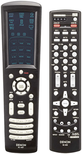 The AVP-A1HDCI comes with
two remote controls – the RC-1067 which serves as the main zone remote control
and the RC-1070 which functions as a simplified remote for the main zone as
well as multi zone control. The RC-1067
is an updated version of their learning/multibrand touchscreen
electro-luminescent remote originally offered with the AVR-5805. Gone however are some of the Colecovision style membrane push
buttons and instead this remote consists of real push buttons for main function
control such as selecting inputs, adjusting volume, changing channels, and
using a push button fly wheel to navigate the OSD menus. The touchscreen is only used to select the
device you want the remote control to operate or the surround/soundfield mode
you desire. The tactile feel of this
remote has been greatly improved and you can pretty much operate it with one
hand without any issues. I was also
pleased to see the RC-1067 requires only 2AA batteries unlike its predecessor
that required 4AAA’s to operate. I have
a few major gripes with this remote starting with the fact that you can no
longer select what PLIIx mode you want to be in via a remote hot key. Another annoyance is the very inconspicuously
“M.SEL/Home” button that when pressed will select which HDMI output you desire
to send video signal to. The first time I accidentally hit this button in my dark theater room I
lost my picture and had to trouble shoot for nearly half an hour until I realized the
culprit. This is a dangerous button to
be offered with such easy access.
The AVP-A1HDCI comes with
two remote controls – the RC-1067 which serves as the main zone remote control
and the RC-1070 which functions as a simplified remote for the main zone as
well as multi zone control. The RC-1067
is an updated version of their learning/multibrand touchscreen
electro-luminescent remote originally offered with the AVR-5805. Gone however are some of the Colecovision style membrane push
buttons and instead this remote consists of real push buttons for main function
control such as selecting inputs, adjusting volume, changing channels, and
using a push button fly wheel to navigate the OSD menus. The touchscreen is only used to select the
device you want the remote control to operate or the surround/soundfield mode
you desire. The tactile feel of this
remote has been greatly improved and you can pretty much operate it with one
hand without any issues. I was also
pleased to see the RC-1067 requires only 2AA batteries unlike its predecessor
that required 4AAA’s to operate. I have
a few major gripes with this remote starting with the fact that you can no
longer select what PLIIx mode you want to be in via a remote hot key. Another annoyance is the very inconspicuously
“M.SEL/Home” button that when pressed will select which HDMI output you desire
to send video signal to. The first time I accidentally hit this button in my dark theater room I
lost my picture and had to trouble shoot for nearly half an hour until I realized the
culprit. This is a dangerous button to
be offered with such easy access.
I was quite puzzled by how difficult I found it to use the radio on this product. For one they didn’t integrate the HD radio feature into the standard AM/FM tuner input. Instead there were two discrete inputs and antenna hook ups for both. Since you can’t control any tuner functions via the front panel of the processor, you have to rely solely on the remote control. To make matters worse, once you select the tuner input, you have to navigate the touchscreen. To operate AM/FM, you have to select “TU” then “Dev1”. For HD radio, the input is labeled “DTU” which makes little sense. In order to operate it, you must select “Net/DTU” and “Dev2” via the touchscreen of the remote. In either case you won’t be allowed to use the center circle hard buttons or CH up/down functions to make your selections for tuner mode or changing stations. A tuner shouldn’t be this difficult to operate in this day and age and I suspect it will really discourage its use among casual users. Finally the location of the on/off buttons seem a little out of place as I found myself accidentally hitting the “off” button on many occasions since that is exactly where I position my thumb when holding the remote with my right hand.
Update on HD/FM Tuners: 07/2/08
According to Denon, you can use the HD tuner for HD and normal FM program material. Thus they recommend using the HD tuner input solely for the main zone and FM tuner for other zone applications.
The RC-1070 is a nice addition and perhaps the most comprehensive multi zone remote control I’ve seen. You can pretty much control the entire processor with this remote as it has virtually all of the functionality of the RC-1067 but in push button version. Despite my criticisms, I still feel this is the nicest remote solution I’ve seen Denon offer in their products and I was relieved at how intuitive they were to operate most of the time.
Listening Tests
It was time to see if the AVP-A1HDCI had the sonic chops to party with the big boys. Using the matching POA-A1HDCI 10CH amp with my front channels configured for “Bi-amp” mode where the bottom bass portions of my RBH T-30LSE’s were running as 2 of the 4 dedicated subwoofers in my system, I was ready to go.
Reference Equipment
I installed
the Denon AVP-A1HDCI into the
premier theater room of the Audioholics Showcase home consisting of the
matching Denon POA-A1HDCI 10 channel amplifier, RBH Sound T-30LSE Signature
speaker system, dual Velodyne DD-15 subwoofers, Denon DVD-5910CI
and Toshiba HD-A2 HD DVD players
and the Epson Pro Cinema 1080UB 1080p LCD projector.
The cables include, Sonicwave HDMI and digital toslink/coax from Impact
Acoustics, 1694A Canare terminated RCA cables and 10AWG speaker cable from Blue
Jeans cable and DVI Gear SHR HDMI
cables.
CD: James Taylor – That’s
Why I’m Here I’m not a huge James Taylor fan. In fact most of his music kinda puts me to
sleep. But his CD’s have some incredibly
good fidelity and I like listening to the title track
because it really helps me gauge if the front
channels are imaging correctly and everything sounds tonally balanced. When I engaged Audyssey, found the vocals to
be more forward, but the highs to be a bit too laid back. I toggled between “Audyssey” and “Flat” and
preferred the latter. With DEQ engaged,
the bass was more prominent and full, especially at low listening levels. Toggling on/off Audyssey revealed some
interesting sonic observations. With
Audyssey engaged, James Taylor’s voice seemed more anchored and forward, but
the snare drums seemed to loose depth in the soundstage. The speakers didn’t seem to sound quite as
wide but instead took on a more focused, intimate sound. My personal preference was No Audyssey in
this case but it was really a matter of taste over which end result was more
accurate. I ultimately settled on
“Audyssey Bypass L/R” to achieve the benefits of bass correction on my subs and
activation of DEQ, while not EQ’ing the main channels.
I’m not a huge James Taylor fan. In fact most of his music kinda puts me to
sleep. But his CD’s have some incredibly
good fidelity and I like listening to the title track
because it really helps me gauge if the front
channels are imaging correctly and everything sounds tonally balanced. When I engaged Audyssey, found the vocals to
be more forward, but the highs to be a bit too laid back. I toggled between “Audyssey” and “Flat” and
preferred the latter. With DEQ engaged,
the bass was more prominent and full, especially at low listening levels. Toggling on/off Audyssey revealed some
interesting sonic observations. With
Audyssey engaged, James Taylor’s voice seemed more anchored and forward, but
the snare drums seemed to loose depth in the soundstage. The speakers didn’t seem to sound quite as
wide but instead took on a more focused, intimate sound. My personal preference was No Audyssey in
this case but it was really a matter of taste over which end result was more
accurate. I ultimately settled on
“Audyssey Bypass L/R” to achieve the benefits of bass correction on my subs and
activation of DEQ, while not EQ’ing the main channels.
DTS CD: Diana Krall – Love Scenes Track #2 “Peel Me a Grape” had Diana’s vocals centered
straight ahead while the bass rattled my floor joists. I was in awe that
despite my room was shaking with so much tactile energy, I still heard all of
the great reverb from the surround channels in the recording and the twang
sound of the bass. There was excellent separation of musical instruments and no sigh of strain or smearing like
I’ve heard on lesser designed systems.
With DEQ engaged, the bass was definitely fuller sounding, but the
surround levels seemed a bit too hot and her voice which was anchored dead
center seemed further away. I toggled
between Audyssey modes and DEQ on/off and ultimately settled on “Audyssey
Bypass L/R” with no DEQ.
Track #2 “Peel Me a Grape” had Diana’s vocals centered
straight ahead while the bass rattled my floor joists. I was in awe that
despite my room was shaking with so much tactile energy, I still heard all of
the great reverb from the surround channels in the recording and the twang
sound of the bass. There was excellent separation of musical instruments and no sigh of strain or smearing like
I’ve heard on lesser designed systems.
With DEQ engaged, the bass was definitely fuller sounding, but the
surround levels seemed a bit too hot and her voice which was anchored dead
center seemed further away. I toggled
between Audyssey modes and DEQ on/off and ultimately settled on “Audyssey
Bypass L/R” with no DEQ.
Editorial Note About Audyssey DEQ
I checked with Audyssey to better understand why I was hearing recessed vocals with DEQ engaged and here is what they told me:Dynamic EQ is only *exactly* right for movie content that is produced to an absolute standard SPL and thus can be directly compared to the SPL measured in your room. Music content is not produced under standardized conditions and so there are cases where Dynamic EQ will be off depending on the reference level at which the music mixer made decisions about how much bass to use.
It is clear that the benefits of DEQ are really source dependent so you must experiment to determine if you prefer using it on the particular program material you’re listening to.
In track #3 “I Don’t Know Enough About You” I actually did hear distortion but quickly realized it was part of the recording possibly caused by preamp clipping during the recording process. The Denon combo was revealing enough to showcase this recording flaw.
CD: Genesis - Live
Over Europe 2007 Nothing put a bigger smile on my face when the
legendary progressive rock band
Genesis got back together for one
last tour to remind the world of their musical genius. In two channel stereo, the sound of this
double disc concert CD is a bit flat and sterile, but the experience is far
more enjoyable once you engage Prologic IIx Music Mode. I started out with track
#3 “Land of Confusion” and toggled between DEQ
on/off and Audyssey modes and settled on DEQ On and Audyssey Bypass L/R. This allowed me to achieve better bass
response to make the recording sound fuller and more involving.
Nothing put a bigger smile on my face when the
legendary progressive rock band
Genesis got back together for one
last tour to remind the world of their musical genius. In two channel stereo, the sound of this
double disc concert CD is a bit flat and sterile, but the experience is far
more enjoyable once you engage Prologic IIx Music Mode. I started out with track
#3 “Land of Confusion” and toggled between DEQ
on/off and Audyssey modes and settled on DEQ On and Audyssey Bypass L/R. This allowed me to achieve better bass
response to make the recording sound fuller and more involving.
Track #4 “In the Cage” liked being played loudly on this system. Towards the middle of the song as they progress over to the “Cinema Show” instrumental, the music was so enveloping that I was starting to feel that “better than being there” experience on this Denon rig.
SACD: Patricia Barber – Night Moves Track #1
“Bye Bye Blackbird” revealed that
the Denon combo could handle delicate musical passages with authenticity. Piano
music is very hard to accurately reproduce as the harmonic overtones are quite
complex. The combined low noise floor of the AVP-A1HDCI
and POA-A1HDCI revealed all of the nuances with plenty of depth at airiness. I
heard all of the presence in the cymbals of Track
#2 “Invitation” with plenty of body in the music. Bass was abundant and well
extended in track #3 “Yesterdays”. I
switched the processor to pure direct and just sat back
listening to pristine two-channel audio that would make even the most critical
of audiophiles drool over. The Denon
gear was driving my speaker system with ease and adding no sonic nasties that
would distract my enjoyment of the listening session no matter what power level
I was running at. DEQ engaged boosted
the bass on this already bass heavy recording a bit too much for my liking so I
ultimately left it off. I was again
tossed between my preferences of Audyssey on/off as I felt like the vocals were
improved with it on, but the stereo separation and depth of soundstage seemed
slightly diminished. By now I was
realizing the subtle differences of Audyssey on/off were more noticeable in two
channel recordings than they were in multi channel. So my advice to doubters is to run “Audyssey
Bypass L/R” for two channel sources should you face a similar dilemma to what I
have reported here.
Track #1
“Bye Bye Blackbird” revealed that
the Denon combo could handle delicate musical passages with authenticity. Piano
music is very hard to accurately reproduce as the harmonic overtones are quite
complex. The combined low noise floor of the AVP-A1HDCI
and POA-A1HDCI revealed all of the nuances with plenty of depth at airiness. I
heard all of the presence in the cymbals of Track
#2 “Invitation” with plenty of body in the music. Bass was abundant and well
extended in track #3 “Yesterdays”. I
switched the processor to pure direct and just sat back
listening to pristine two-channel audio that would make even the most critical
of audiophiles drool over. The Denon
gear was driving my speaker system with ease and adding no sonic nasties that
would distract my enjoyment of the listening session no matter what power level
I was running at. DEQ engaged boosted
the bass on this already bass heavy recording a bit too much for my liking so I
ultimately left it off. I was again
tossed between my preferences of Audyssey on/off as I felt like the vocals were
improved with it on, but the stereo separation and depth of soundstage seemed
slightly diminished. By now I was
realizing the subtle differences of Audyssey on/off were more noticeable in two
channel recordings than they were in multi channel. So my advice to doubters is to run “Audyssey
Bypass L/R” for two channel sources should you face a similar dilemma to what I
have reported here.
HD DVD: Pat
Metheny – The Way Up Live Pat Metheny is one of those select guitarists that have
a signature sound only he can produce.
He surrounds himself with some of the world’s best musicians and
produces complex rich music few can master.
His playing is so effortless and fluid that you tend to forget about the
musicians and just focus on the sonic nirvana you’re being surrounded by. This HD DVD
is one of the reasons why my HD DVD
player still occupies shelf space on my rack.
Pat Metheny is one of those select guitarists that have
a signature sound only he can produce.
He surrounds himself with some of the world’s best musicians and
produces complex rich music few can master.
His playing is so effortless and fluid that you tend to forget about the
musicians and just focus on the sonic nirvana you’re being surrounded by. This HD DVD
is one of the reasons why my HD DVD
player still occupies shelf space on my rack.
The symphonic performance of this disc can best be described as a classical masterpiece composed with progressive jazz styling. The disc is basically one long song divided only by name (“Opening”, “Part One”, “Part Two” and “Part Three”). Leave it to Pat to keep the names simple and distinct. With DEQ engaged in conjuncture with “Audyssey Bypass L/R”, I was fired up to spend an evening with the Pat Metheny group in the comforts of my theater room. My brother – a classically trained jazz guitarist, was with me in the audience and we sat back to take a listen. The sound quality was quite good considering the disc was only limited to Dolby Digital Plus. I did note some areas of compression, but overall the surround envelope was excellent and the bass plentiful. No matter how loudly I turned it up, the sound remained clean and effortless. I sat in sonic delight while my brother was in awe at the picture quality of this 1080i HD disc upscaled to 1080p and processed by Realta via the AVP-A1HDCI. He was enthralled that he could see Pat up close and better learn the finger positions of his guitar work. Incidentally within a couple of days, my brother was playing some of the most complex passages on this disc on his guitar and he commented that this wouldn’t have been possible so quickly without such a nice birds eye view. Needless to say, the picture and audio quality being reproduced on the Denon system in my theater room was nothing short of stunning.
HD DVD: The Phantom of the Opera The picture
and sound quality of this HD disc is excellent.
The opening score for Phantom of the Opera sounded marvelous and the
surround field was even more expansive with DEQ engaged. I didn’t detect vocal recession with Audyssey
and DEQ engaged like I did on the Diana Krall disc and overall the experience
seemed more enveloping with very natural panning between surround channels and
front to back. The visuals were as stunning as the audio and
I had a difficult time turning the disc off despite I was initially using it
for quick reference for this
review.
The picture
and sound quality of this HD disc is excellent.
The opening score for Phantom of the Opera sounded marvelous and the
surround field was even more expansive with DEQ engaged. I didn’t detect vocal recession with Audyssey
and DEQ engaged like I did on the Diana Krall disc and overall the experience
seemed more enveloping with very natural panning between surround channels and
front to back. The visuals were as stunning as the audio and
I had a difficult time turning the disc off despite I was initially using it
for quick reference for this
review.
No matter what source material I threw at the Denon separates combo, it was reproduced with the highest level of fidelity I’ve heard in my theater room. While I didn’t always prefer the sonic attributes Audyssey and DEQ had to offer, I did find they greatly enhanced my listening pleasure depending on source material, especially for movies where I felt DEQ worked best. I plan on recalibrating my setup again to see if I can improve the overall results. I am confident that the Audyssey Pro upgrade will further allow me to fine tune the results and achieve an even higher level of enhancement.
Suggestions for Improvement
There is little to improve on a “does everything” product that happens to do it all quite well. That being said, I did find a few things I’d like to see adjusted or added to the AVP-A1HDCI as tabulated below.
- Solution to volume scaling issue
- Provision for “3SP L/R/LFE Super” setting in bass management
- Ability to enable Audyssey correction for subwoofer channels only
- Ability to limit Audyssey maximum gain
- Easier usability of AM/FM / HD tuners
Considering this is a fully firmware upgradeable product, most of my criticisms could likely be addressed should other uses agree with my assessment and motivate Denon to make some changes.
Denon AVP-A1HDCI Measurements and Analysis
Frequency Response & Distortion
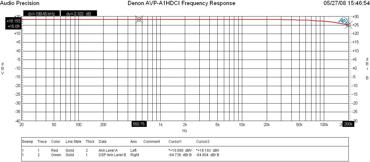
Denon AVP-A1HDCI Preamp Frequency Response
I measured a ruler flat frequency response with a -3dB point around 200kHz in all 2CH stereo modes (ie. Pure direct, Stereo direct). The AVR-5308CI measured similar bandwidth as well.
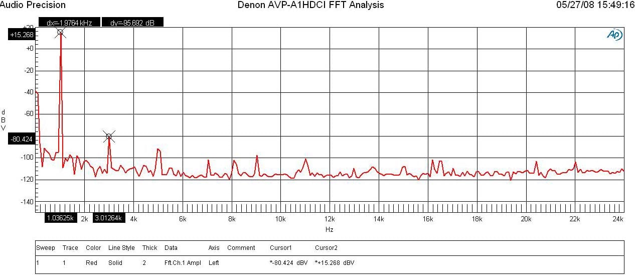
Denon AVP-A1HDCI Preamp FFT Distortion Analysis
With 200mVin, I set the master volume until I reached 1Vrms out of the preamp. The FFT plot was so clean that I couldn’t measure any appreciable distortion products until I ramped up the signal level to drive the output to nearly 6Vrms. At that point, I measured (15.268+ 80.424)dBv = 95.69dB or 100*alog^-1(-95.69/20) = .0002% THD + N which is among the lowest distortion I’ve ever measured in a preamp regardless of price. The AVR-5308CI didn’t compete here as the measurable harmonics were about 6dB worse driving an output of 1Vrms than they were on the AVP-A1HDCI outputting nearly 6Vrms.
I measured about 15.5dB of gain via the balanced and unbalanced outputs of the AVP-A1HDCI preamp (with source level set to 0dB on the particular input and channel trims set to 0dB). The preamp has plenty of output capability as evident by the following measurements all taken @ < 0.1% THD +N:
Balanced:
- Vmax out = 14Vrms
- Vmax In = 15.5Vrms
Ubalanced:
- Vmax out = 7.2V (3.8Vrms was the limit on the AVR-5308CI)
- Vmax in = 8V
Though this is more than enough output to drive any power amplifier to maximum capability (THX amps require about 2Vrms to reach full power) the gain is structured a bit low requiring the input signal to be larger than normal to reach high output levels. This explains why I always had to peg the volume near max on low compression sources. I personally wished Denon would have followed a more common gain structure in this processor like I’ve seen on other A/V products as follows:
- Unbalanced: Av = 17dB
- Balanced: AV = 23dB (6 dB higher than unbalanced)
SNR
With 200mVin and 1Vout, SNR = 95dB (unweighted) in pure direct mode. This is an excellent measurement, and with its ample drive capability proves the AVP-A1HDCI is a top notch preamplifier that will satisfy even the most critical audiophile.
Crosstalk
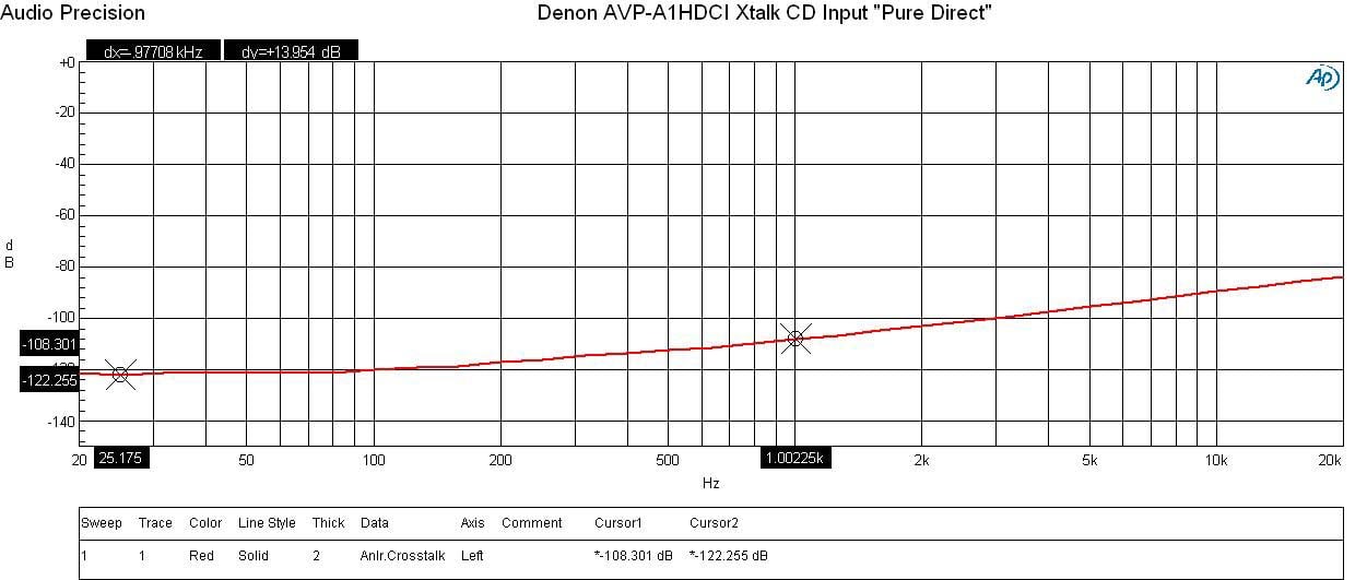
Denon AVP-A1HDCI Crosstalk Measurement at Full Rated Power vs Frequency
Running a full range frequency sweep from the preamp, it displayed superb crosstalk measurements between the front left and right channels of over 108dB @ 1kHz with a slight rise with increasing frequency due to capacitive coupling and actually no increase at low frequencies indicating no magnetic coupling was present. The separated power supplies Denon boasts in this design truly show off their benefit via this measurement as evident when I measured about 20dB worse crosstalk on the AVR-5308CI under similar test conditions. I did note that when I engaged the bass management circuitry, the crosstalk measurement level went up about 10dB which is likely because of the added trace paths and associated circuitry but at these low levels it’s more academic than a concern of audibility.
Measurement Wrap Up
Every measurement I made of the AVP-A1HDCI was benchmark. This processor has one of the cleanest preamp sections I've seen and certainly has a top notch DAC section that few products regardless of price can compete with. Whether you're listening to redbook CD's, DVD-A, SACD or the latest hidef formats such as Dolby TrueHD and DTS HD, you can be assured that the AVP-A1HDCI will process those formats with the highest resolution possible.
Denon AVP-A1HDCI Recommendations & Conclusion
This processor is not a product for a neophyte. It has nearly infinite configuration options to dial in optimal picture and sound quality that is best setup by a qualified installer or experienced home theater aficionado. While most home theater fans can run through the motions following the sub par users manual, you will want someone who can spend the time to install it properly that can really eek out all of the performance capabilities this system has to offer. The POA-A1HDCI amplifier is a good compliment to this processor since they aesthetically match each other and are also digitally linked together for easier assignability of channels and amplifier mode configurations. Make sure you’ve got plenty of rack space for these units as they are enormous and do run quite warm requiring adequate ventilation to keep them cool. Take the time to set this baby up correctly and it will reward you with great sonics and plenty of music streaming options to ensure you never run out of things to listen to.
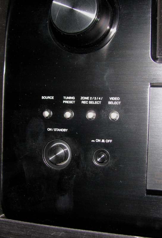
Denon AVP-A1HDCI Power Button
Conclusion
 The Denon
AVP-A1HDCI represents bleeding
edge technology that only a select few manufacturers can compete with
regardless of price. This processor
truly is a master of all domains. It’s
not cheap to own this combo set from Denon, but such is the case with statement
pieces and first implementers of new technologies. It’s a bit difficult to quantify its value as
compared to their very own AVR-5308CI
A/V receiver, it seems to be overpriced since the latter does mostly everything
this processor does albeit maybe not as elegantly. But when you compare it to other more
expensive “high end” processors, many of which don’t offer video processing and
upscaling, room correction, or TrueHD / DTS HD decoding, it seems to be quite a
bargain.
The Denon
AVP-A1HDCI represents bleeding
edge technology that only a select few manufacturers can compete with
regardless of price. This processor
truly is a master of all domains. It’s
not cheap to own this combo set from Denon, but such is the case with statement
pieces and first implementers of new technologies. It’s a bit difficult to quantify its value as
compared to their very own AVR-5308CI
A/V receiver, it seems to be overpriced since the latter does mostly everything
this processor does albeit maybe not as elegantly. But when you compare it to other more
expensive “high end” processors, many of which don’t offer video processing and
upscaling, room correction, or TrueHD / DTS HD decoding, it seems to be quite a
bargain.
If you’re looking for the very best home theater separates solution, I highly recommend considering the Denon AVP-A1HDCI pre/pro and POA-A1HDCI ten channel power amp. While their model #’s aren’t impressive sounding, and the associated name doesn’t quite have the prestige of a Levinson or Krell, you can rest assured the Denon products have it where it counts in performance and features and are pound for pound a better value than virtually all of the super high end products on the market. From its Realta video processing engine, to its sophisticated Audyssey room correction, top notch construction and component usage, you’re getting Mercedes level performance and refinement at Acura prices. Your high end audio snob friends may snicker at this system, especially since they likely spent 2-3 times more for hollow boxes, but I suggest humbling yourself by saying nothing. You don’t want everyone driving the same car you’re driving, do you?
For more info, Visit the Denon AVP-A1HDCI product page.
Denon
Electronics
www.usa.denon.com
100 Corporate Drive
Mahwah, N.J. 07430-2041
Denon
AVP-A1HDCI MSRP: $7,000
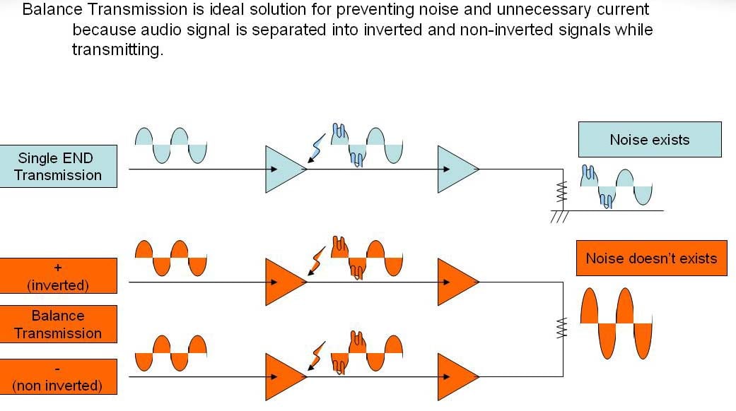
Denon AVP-A1HDCI Balanced Transmission Further Explored
By request, Denon sent me detailed block diagrams of these products that illustrate the fully balanced design. Most companies don’t follow a balanced convention through all of the circuit stages because it adds significant cost and complexity. The advantage of such designs ensures the very lowest distortion and noise floor which were very apparent when I put these units on the bench and conducted my measurements.
The AVP-A1HDCI utilizes two dedicated torroid and separate power supply banks with one being for the preamp output drivers and another being for the DAC sections. Digital audio and video circuitry are isolated on separate boards and are also fed independent post filtered isolated power to ensure the cleanest possible signal paths are maintained throughout the entire design.
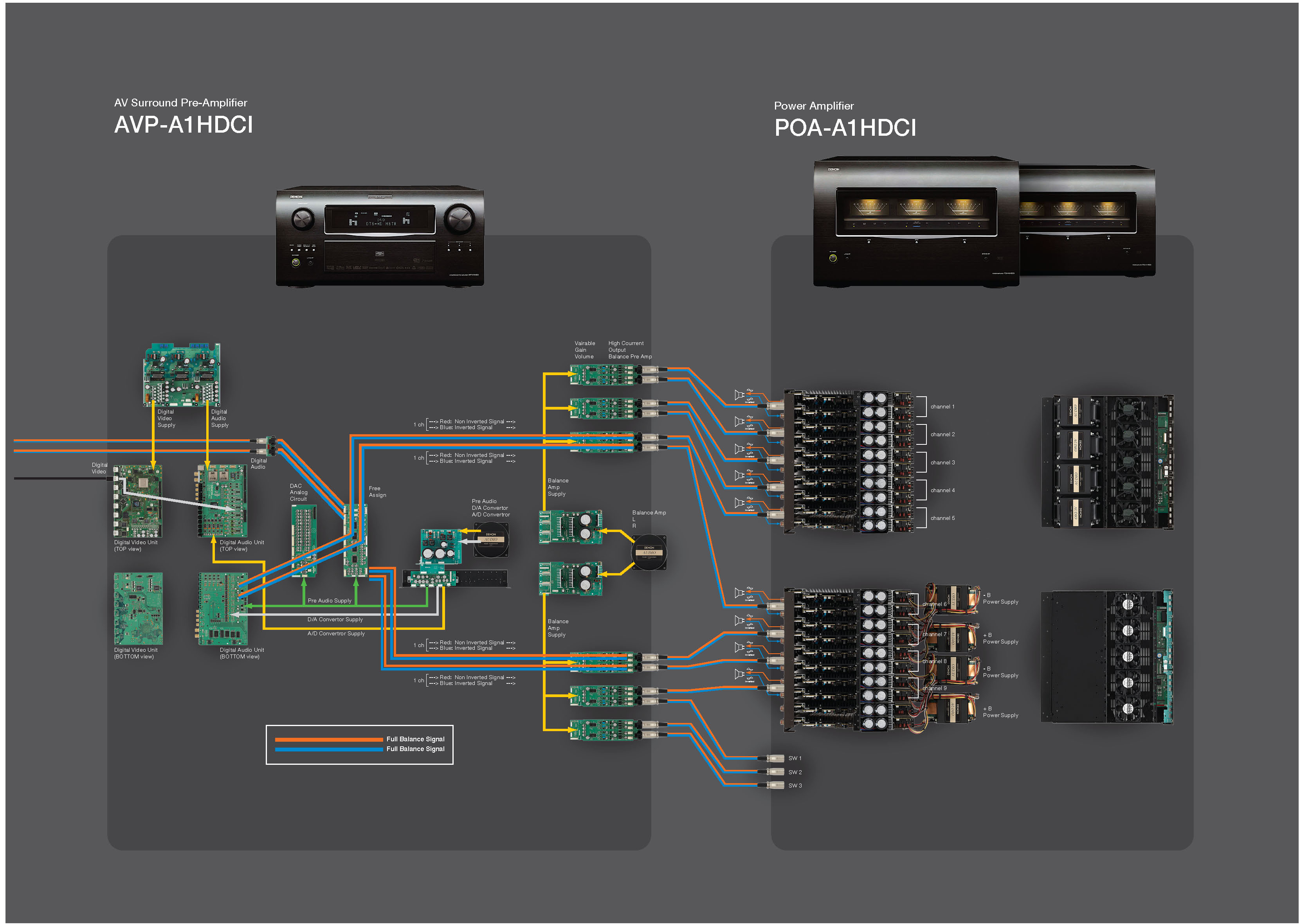
AVP-A1HDCI & POA-A1HDCI Block Diagrams
The POA-A1HDCI 10 channel amplifier boasts 4 large E-core power transformers (2 for + rails and 2 for – rails) and 20 x 10,000uf capacitors (2 per channel) for a whopping 200,000 uf total power supply storage. When bridging two channels, you are essentially coupling the power supply potential of each mono block amplifier and doubling the amplifiers voltage swing for a dynamic potential of up to 4 times the delivered power into that particular load.
The Score Card
The scoring below is based on each piece of equipment doing the duty it is designed for. The numbers are weighed heavily with respect to the individual cost of each unit, thus giving a rating roughly equal to:
Performance × Price Factor/Value = Rating
Audioholics.com note: The ratings indicated below are based on subjective listening and objective testing of the product in question. The rating scale is based on performance/value ratio. If you notice better performing products in future reviews that have lower numbers in certain areas, be aware that the value factor is most likely the culprit. Other Audioholics reviewers may rate products solely based on performance, and each reviewer has his/her own system for ratings.
Audioholics Rating Scale
 — Excellent
- — Very Good
- — Good
- — Fair
- — Poor
| Metric | Rating |
|---|---|
| Frequency Response Linearity | |
| SNR | |
| Multi-channel Audio Performance | |
| Two-channel Audio Performance | |
| Network Features | |
| Video Processing | |
| Bass Management | |
| Build Quality | |
| Fit and Finish | |
| Ergonomics & Usability | |
| Ease of Setup | |
| Features | |
| Remote Control | |
| Performance | |
| Value |
Gene manages this organization, establishes relations with manufacturers and keeps Audioholics a well oiled machine. His goal is to educate about home theater and develop more standards in the industry to eliminate consumer confusion clouded by industry snake oil.
View full profile