
Ram Electronics HS Speaker Cable Review
Ram Electronics HS Speaker Cable
- Product Name: HS Speaker Cable
- Manufacturer: Ram Electronics
- Performance Rating:

- Value Rating:
- Review Date: May 28, 2009 07:25
- MSRP: $ 43.01 - $150.43 (3-70ft)
- Crimped with WBT Gold plated crimp sleeve ferrules - easy to replace ends, or use without
- 11 AWG per conductor, available in Bi-wire configuration HSB, other custom configurations by request.
- Exceptionally durable and resistant to tough environments
- Gold plated locking banana plugs with gold plated locking screws or optional WBT spades or banana plugs for the ultimate in current transfer, more Terminations available soon
- Professionally assembled and tested.
- Finest combination of quality, performance and value available
- 30 day unconditional return
Pros
- Excellent build quality
- Top of the line components
- Great performance
Cons
- Only comes in gray without added cost
- Pricy compared to some of the competition
Ram Electronics HS Series Cables Introduction
Since before working for Audioholics the Canare 4S11 cables have been my preferred choice for speaker cables. They may not be the best choice for tight spaces or in-wall runs but they look a lot better than the Belden alternative and generally have a lot of weight and heft to them. They just feel like quality. Ram Electronics is giving you access to these cables with top of the line termination options. While you can find some brands for cheaper, if you're looking for the best construction, looks, and components, the HS cables are for you.
Ram Electronics HS Speaker Cable Build Quality
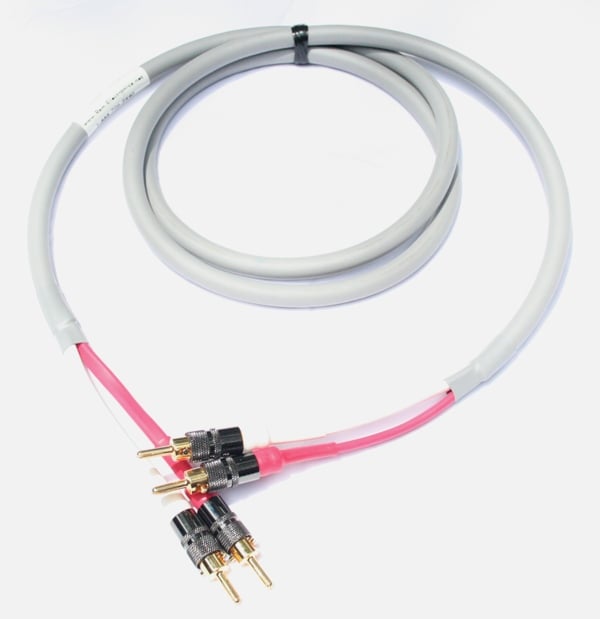 The Ram Electronics HS
series of cables is built on the tried but true Canare 4S11 cable. The Canare
4S11 is four stranded and PVC wrapped cables in a single insulated PVC jacket.
They are color coded white and off white, red and pink. When you combine the
two whites and reds into a single termination point, you get an effective gauge
of 11awg. This is more than enough for all but the most ridiculously long runs.
The outside of the cable is thick and hefty which allows you to set it down and
not worry about it moving too much. It also affords the 4 internal cables a
level of protection that your typical speaker cable just doesn't have. The
jacket also has a sort of velvety finish that is very pleasing to the touch.
The Ram Electronics HS
series of cables is built on the tried but true Canare 4S11 cable. The Canare
4S11 is four stranded and PVC wrapped cables in a single insulated PVC jacket.
They are color coded white and off white, red and pink. When you combine the
two whites and reds into a single termination point, you get an effective gauge
of 11awg. This is more than enough for all but the most ridiculously long runs.
The outside of the cable is thick and hefty which allows you to set it down and
not worry about it moving too much. It also affords the 4 internal cables a
level of protection that your typical speaker cable just doesn't have. The
jacket also has a sort of velvety finish that is very pleasing to the touch.
The HS cables came terminated with Ram’s house brand banana plugs at both ends. A WBT connector option is available under the HSW moniker. Many companies claim to use WBT connectors with their cables. The fact is that the WBT connectors are very pricey. When you compare them to the competition, you can see why. Ram’s house brand is a bit thicker and more substantial than the rivals. The difference between the Ram cables and other Carare 4S11 offerings is that they are construct using the WBT crimp ferrules under the quality house banana connectors and heat shrink on the cable pairs. This makes identifying which cable is which very easy and it also keeps the two neat. One thing missing was the red/white designation on the actual banana plug. In the past I've seen companies take a small piece of heat shrink and use that for marking (there is even a little groove for that in the plug).
![]() The only marking on
the cable other than the stamps from Canare was a heat-shrinked Ram label with
their website and phone number on it. The label looks a little messy as either
the shrinking process or the cable rubbing against itself seems to have smudged
or dirtied the white label. I'm actually a little surprised that Ram didn't
decide to wrap this cable in something else like techflex. While techflex, in
particular, would have reduced the flexibility (ironically) of the cable, it
would have given the end user some color options. Canary gray is their standard
offering, techflex options are available in black with white line or white with
black line as a special for an additional $1.00 per foot.
The only marking on
the cable other than the stamps from Canare was a heat-shrinked Ram label with
their website and phone number on it. The label looks a little messy as either
the shrinking process or the cable rubbing against itself seems to have smudged
or dirtied the white label. I'm actually a little surprised that Ram didn't
decide to wrap this cable in something else like techflex. While techflex, in
particular, would have reduced the flexibility (ironically) of the cable, it
would have given the end user some color options. Canary gray is their standard
offering, techflex options are available in black with white line or white with
black line as a special for an additional $1.00 per foot.
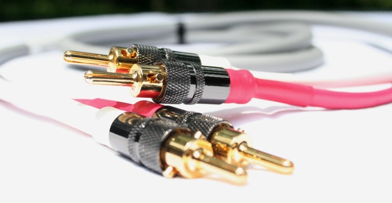 Options are not a
problem on the termination front. Ram offers spades, banana plugs, or with the
WBT gold plated crimp sleeve ferrules exposed. What's a crimp sleeve? Well,
essentially it is a gold plated cover for the end of the wires for use with the
WBT connectors. This crimp is made with a commercial tool that gives a gas
tight, cold weld of the ferrule to the 14awg joined wires. This results in
an 11awg equivalent speaker cable that will not oxidize or require
re-termination. In addition, you can change the connectors to any set
screw type connector in the field should your needs change. You can actually
use the wire without the termination and just the sleeve if you want. It would
be similar to a pin (more popular in Europe than the US). This is where the Ram offering distinguishes itself from the rest of the
pack. Even with DIY options, changing termination types is a real hassle. With
the ferrules crimp method, it is easy to switch types AND
you don't lose any cable length. In order to do this with the cables that I had
in for review, I'd have to remove the heat shrink from the end of the cables. Then
I’d have to loosen the two screws out and the banana plug to remove the
termination. Switching the termination type should be only a matter of minutes
(if that). Right now, Ram only offers banana plugs and spades but their site
says they will be adding more in the future.
Options are not a
problem on the termination front. Ram offers spades, banana plugs, or with the
WBT gold plated crimp sleeve ferrules exposed. What's a crimp sleeve? Well,
essentially it is a gold plated cover for the end of the wires for use with the
WBT connectors. This crimp is made with a commercial tool that gives a gas
tight, cold weld of the ferrule to the 14awg joined wires. This results in
an 11awg equivalent speaker cable that will not oxidize or require
re-termination. In addition, you can change the connectors to any set
screw type connector in the field should your needs change. You can actually
use the wire without the termination and just the sleeve if you want. It would
be similar to a pin (more popular in Europe than the US). This is where the Ram offering distinguishes itself from the rest of the
pack. Even with DIY options, changing termination types is a real hassle. With
the ferrules crimp method, it is easy to switch types AND
you don't lose any cable length. In order to do this with the cables that I had
in for review, I'd have to remove the heat shrink from the end of the cables. Then
I’d have to loosen the two screws out and the banana plug to remove the
termination. Switching the termination type should be only a matter of minutes
(if that). Right now, Ram only offers banana plugs and spades but their site
says they will be adding more in the future.
Of course, only a true Audioholic would care what his speaker cables look like - most people just care about two things - cost and performance.
Performance
Overall, I was really impressed by the HS series of cables. The Ram brand banana plugs worked well with every 5-way binding post I encountered. The additional girth of the connection made it a little easier to lock down the plug. On the back of some AV receivers, you find very little room. While you'd think the additional girth would make operating the plug harder, in most cases I found that it made it easier. I was able to better grip the sides than the thinner terminations. The only exception was when I had multiple plugs right next to each other (covering three sides). No matter your termination option, the backs of some of these receivers were made for leprechauns and hobbits.
Ram Electronics HS Measurements and Analysis
By Gene DellaSala
Using our Wayne Kerr 6420 Impedance Analyzer which graces our Test Equipment Laboratory, I measured all of the critical metrics which directly affect cable performance. I charted the results with some of the most recent speaker cables we’ve reviewed for comparative purposes.
Cable Metric Definitions
|
Rdc - |
Commonly referred to DCR which is the series resistance of a cable at zero frequency. |
|
Rac - |
The resistive portion of the cables series resistance as a function of frequency due to skin effect. |
|
Rs - |
Total Series Resistance (mohms) measured tip to tip at one end of the cable while the other end is shorted. Note: Rs = Rac + Rdc (minus instrumentation inaccuracies identified below) |
|
Ls - |
Series Inductance (uH) measured tip to tip at one end of the cable while the other end is shorted. |
|
Cp - |
Parallel Capacitance (pF) measured tip to tip at one end of the cable while the other end is open circuited. |
Note about electrical cable resonance
Editorial Note on Cable Measurement Test Set-up
All of the measurements were completed on a fully calibrated and certified Wayne Kerr 6420 Impedance Analyzer. The 6420 was calibrated for full frequency bandwidths and for greater accuracy the measurements and calibration process was repeated twice for consistency.All cable lengths measured were 20 feet and divided by their length for a normalized per foot measurement. At low frequencies the results illustrate Rs being lower than Rdc, which is inaccurate, as Rs tends towards Rdc as frequency approaches zero or DC. The LCR measurement derives Rs from signal phase and amplitude, while a DC meter measures exactly what it is looking for, thus this discrepancy is likely due to a meter resolution issue, as the meter in AC mode does not sport the high accuracy it would in DC mode. The cable should ideally be modeled as multiple parallel resistors, and those resistors treated as a lumped element in series with an ideal inductor.
Each resistor is a frequency dependent element, and the inner ones fall out as the frequency increases. It is important to note the difference in measuring techniques, and caution the reader not to attempt to derive any relationships with the two numbers, as the absolute accuracy between the methods has not been established. However, the rising trend of Rs vs frequency is indicative of increased Rac due to skin effect and should also be noted.
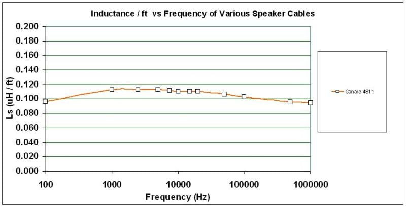
Inductance vs Frequency
The Canare 4S11 has appreciably lower inductance than standard 10 or 12AWG zip cord. The series inductance was measured to be under 0.120uH/ft which is an excellently low figure for such a low gauge cable and non-fancy cable geometry.
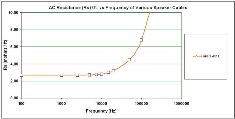
AC Resistance vs Frequency
The Canare 4S11 measured to have an effective gauge of 11AWG which is low just like we like it for speaker cables. The cable didn’t start to appreciably skin until well out of the audio band (>50kHz) which is more than adequate for a high performance cabling solution which will cause no audible harm to your system.
For a more detailed discussion on Skin Effect, see:
Skin Effect Relevance in Speaker Cables
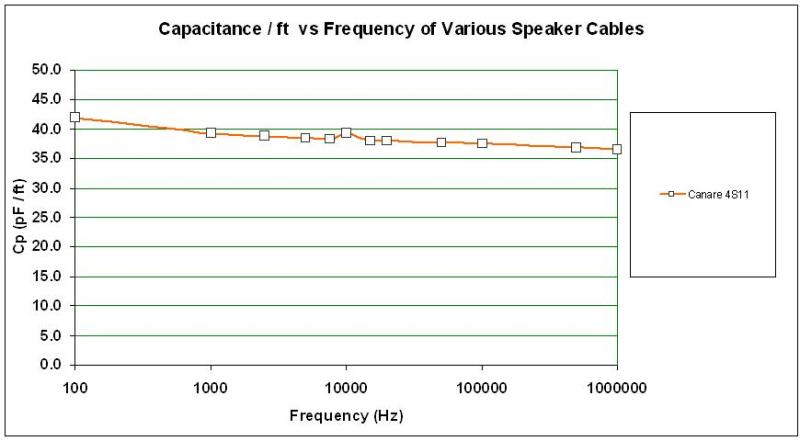
Capacitance vs Frequency
The Canare 4S11 cable capacitance is under 40pF/ft which is commendably low and should not present any amplifier stability issues, even for relatively long cable runs for even the least robustly designed amplifiers.
Ram Electronics HS Cables Cost and Conclusion
 The fact is that you
can get the exact same cable (minus the terminations) at other outlets for a
substantially reduced price over the Ram offering.
To the right is a picture of the Ram versus one of their competitors. As you
can see, while the cables are the same, the fit and finish of the Ram is better
and the locking banana plugs are a bit bigger than the competitor. Inside, the
competitor just has bare wire instead of the ferrules crimp. The question you
should be asking is if those things are worth the extra price. Regardless, if
you didn't value shop, the Ram cables aren't outrageously priced. Compared to
esoteric offerings that uses the
same cable but wraps it in techflex so
you can't tell, they are downright cheap.
The fact is that you
can get the exact same cable (minus the terminations) at other outlets for a
substantially reduced price over the Ram offering.
To the right is a picture of the Ram versus one of their competitors. As you
can see, while the cables are the same, the fit and finish of the Ram is better
and the locking banana plugs are a bit bigger than the competitor. Inside, the
competitor just has bare wire instead of the ferrules crimp. The question you
should be asking is if those things are worth the extra price. Regardless, if
you didn't value shop, the Ram cables aren't outrageously priced. Compared to
esoteric offerings that uses the
same cable but wraps it in techflex so
you can't tell, they are downright cheap.
Conclusion
Ram Electronics HS Speaker Cable
$ 43.01 - $150.43
RAM
Electronics Industries Inc.
1704
Taylors Lane
Cinnaminson, NJ
08077
Toll Free: 888-726-2440
Phone: 856-864-0999
About Ram Electronics
Founded in 1977, Ram
Electronics brings over thirty years of manufacturing experience to the Home
Theater cabling market. They established their internet store to sell cabling
solutions online. Over the last 10 years, they have expanded their product
offerings to include a variety of connectivity solutions for home theater
distribution and switching, audio video converters, network connecting, and
many other areas associated with connectivity products. Their popular iPod
cables and Elite Series HDMI cables, which are award winning, use silver-plated
copper wire for better performance. Performance, functionality, plus value are
critical and distinguish them from many of their competitors. Their in-house
expertise uniquely qualifies them to bring the manufacturing practices and
engineering knowledge on their commercial side to the audio, video and network
connecting. They manufacture all custom cables in-house. Many custom cables
have an unconditional return policy and they encourage their customers to
experience their quality and value. Their in-house research and testing on
products enables them to provide technical support and feedback, to their
suppliers.
The Score Card
The scoring below is based on each piece of equipment doing the duty it is designed for. The numbers are weighed heavily with respect to the individual cost of each unit, thus giving a rating roughly equal to:
Performance × Price Factor/Value = Rating
Audioholics.com note: The ratings indicated below are based on subjective listening and objective testing of the product in question. The rating scale is based on performance/value ratio. If you notice better performing products in future reviews that have lower numbers in certain areas, be aware that the value factor is most likely the culprit. Other Audioholics reviewers may rate products solely based on performance, and each reviewer has his/her own system for ratings.
Audioholics Rating Scale
 — Excellent
- — Very Good
- — Good
- — Fair
- — Poor
| Metric | Rating |
|---|---|
| Audio Performance | |
| Build Quality | |
| Appearance | |
| Performance | |
| Value |
As Associate Editor at Audioholics, Tom promises to the best of his ability to give each review the same amount of attention, consideration, and thoughtfulness as possible and keep his writings free from undue bias and preconceptions. Any indication, either internally or from another, that bias has entered into his review will be immediately investigated. Substantiation of mistakes or bias will be immediately corrected regardless of personal stake, feelings, or ego.
View full profile