
Parasound Halo A 21 Amplifier Review
Parasound Halo A 21 Amplifier
- Product Name: Halo A 21 Amplifier
- Manufacturer: Parasound
- Performance Rating:

- Value Rating:
- Review Date: October 19, 2004 19:00
- MSRP: $ 2000
|
|
Pros
- Bridgeable Channels
- Balanced and Unbalanced Inputs
- Diversified features
- Exceptional Build Quality
- Multiple "power on" options
Cons
- Two amplifiers required for 7-channel audio (A 21 and A 51)
- Increased cost associated with two amplifiers
Parasound Halo A 21 Introduction
At first look the Parasound Halo A 21 and A 51 are appealing and robust amplifiers accented by brushed metal finish and a "Halo" aqua blue light around the power button. But an amplifier is not just about cosmetics especially when considering that most Audio Enthusiasts seem more interested in sound quality and features. The A 21 and A 51 amplifiers are both loaded with usable features above and beyond most other amplifiers in today's market.
The understated look of the A 21 / A 51s subtle yet empowered front panel implies a need for a space aged protective shell that contains a powerful yet precious cargo. For example the "P" on the top of the front face glows red to indicate that the unit has AC power as does the "Halo" insignia around the power button which accents the power button with its soft blue glow. Once the power is turned on the soft blue changes to a brighter blue after all circuitry has been initialized. In the center bottom of the front face are the two indicators that verify proper functionality of each channel by glowing with a different shade of blue. On the right bottom is another indicator that glows red if the unit overheats with a redundancy portrayal from the "Halo" insignia that also switches to red.
Halo A 21 Amplifier Build Quality
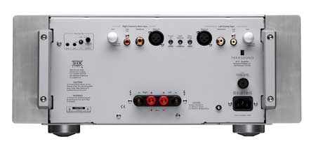
The back of these two amplifiers will meet the highest consumer specifications starting with balanced and unbalanced input connectors for each channel. The designers at Parasound also added pass through connectors for those who have the need to route the signal to another device. These connectors eliminate the need for a Y-adapter dangling off of the back, but they are only provided for the unbalanced (RCA connector).
Parasound cleverly thought to make the input connector larger than the pass through connector so that end users and custom installers wouldn't confuse the two. One of the purposes of the pass through connectors would be to route to another amplifier for bi-amping speakers. Also provided for each channel are gain controls for matching to a variety of different pre-amplifiers or controllers, thereby ensuring that Parasound doesn't limit the usefulness of their amplifiers to only their products.
The speaker connection binding posts are located at the bottom-center of the rear panel. At first I thought it was unusual that the positive connectors were configured on the inside and the negative connectors on the outside but after further investigation this orientation was intentionally designed to enable bridging of the two channels. This atypical placement comes in especially handy for those who desire the more powerful 750 Watts of RMS power into 8 ohms.
There are three dedicated switches for each channel on the back of the amplifier. One can be used to switch between balanced and unbalanced inputs, while the second can be used for switching from stereo to mono or bridged mode. The third and left most is a uniquely implemented grounding switch. The ground switch can be used to help reduce hum or buzz, common with ground noise or ground loops. This hum or buzz comes from the 60 Hz AC or its related harmonics that can intrude the signal when the system ground is not exactly at 0 volts. By changing the position of the switch it separates the signal ground from the chassis ground.
On the left top of the rear panel are two connectors, a three position toggle switch, and a small potentiometer control that can all be used for "power on" options. With the toggle switch in the up position, the audio mode is chosen to bring the potentiometer into play. This mode sets up the A 21/ A 51 to sense an audio signal at the signal inputs which then triggers on the amplifier. The potentiometer is used to set the sensitivity of when the amp turns on which can vary from 50 mV to 200 mV. This is a great feature for users with older equipment that may not have a devoted triggering. The middle position of the switch is a manual trigger which activates the power switch on the front panel. The down position of the toggle enables the 12 volt trigger input common to most new equipment. The clever Engineers at Parasound have also provided a trigger output to carry on to another device. Parasound equipped their amplifiers with a sub-mini connector to match the Halo C 1 / C 2 processors. When connecting other processors such as our reference Integra Research RDC-7 that implements a mini-connector, an adapter is required.
In order to cope with the robust heavy weight of the Halo amplifiers, Parasound provided sturdy handles on the back panel making it easier to install or reposition.
Halo A 21 Amplifier Build Quality - Continued
There are many manufacturers of home theater electronics who place a high emphasis on cosmetics in order to make their gear look as though it where of a higher quality from the outside, though most of them never expect anyone to look under the cover. Parasound is not one of those commonly found cosmetic only companies as the build quality of the outside of their amplifiers are transposed to their inside. When removing the cover of the Halo A 21 and A 51 amplifiers, what becomes most apparent at first glance is their massive toroidal transformers with independent secondary windings for each channel. In essence this feature means that each channel has its own devoted power supply. Combining the transformer with four 80 volt 25,000 microfarad capacitors ensures that the Halo amplifiers are capable of providing plenty of reserve power when the source content requires low impedances and maximum current. Such a design reveals how Parasound justifies their specs with sufficient high quality components implemented within a well conceived design. I also noticed that all of the resistors were 1% tolerance parts thereby ensuring excellent stability for the signal path.
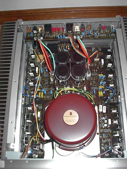
As you can see from the above pictures, there is minimal wiring within the Parasound amplifiers. This means that the signals are carried directly from the connectors to the circuit board which can greatly reduce the possibility of noise infiltration. The A 21 and A 51 also sport internal and external gold plated connectors which tend to be an uncommon feature.
The amplification sections of the A 21 and A 51 were equally as impressive as the other portions of Parsound's design. All of the transistors are discrete as opposed to integrated circuits. The input stage uses matched pairs of JFETs and the driver stage uses matched pairs of MOSFETs which tends to give a less harsh and colored resulting sound. These two stages give the amplifier its sonic signature while the output stage gives the amplifier its high current capabilities. Parasound also implement bipolar transistors in the output stage since such a design typically results in very rugged high current capability.
One of the most noteworthy
operational functions of the Parasound A 21 and A 51 amplifiers are their Class
A-A/B operation. The input and driver stages operate in pure Class A meaning
that the transistors are turned on full all of the time. In essence there are
two banks of transistors in the output stage, one of which is devoted to
positive voltage and the other devoted to negative voltage. The point where the
positive output transistors turn on while the negative transistors turn off (and
vice versa) can cause nasty higher-order odd harmonic distortion (3rd, 5th, 7th,
9th, etc.) for which even very small amounts have been demonstrated as a primary
cause of listening fatigue. In these Parasound amplifiers both the positive and
negative transistors for each channel are always fully on – the definition of
Class A operation - up to 8 watts output per channel. So, for the first 8 Watts
of power, which exceeds the typical average power requirements for music, the
output transistors are always on. For greater than 8 Watts, the transistors are
in class A/B operation where they are partially on when they're not up for duty
and fully on when they are up for duty.
Halo A 21 Amplifier Listening Tests
Unbalanced Audition
I conducted my first audition session using the unbalanced inputs mainly because I did not have my XLR cables yet. All of my comparison comments are with respect to my reference amplifier, the Acurus A250. The A250 turned out to be a great reference amp because it is equally matched in power rating which made it similar enough for comparability.
Involvement
When doing so, I began my two channel audition with the 70s art rock band Yes's CD, "The Ladder," as these reference songs have the involvement and dynamics I seek when comparing product performance. With the Parasound amps driving my speakers, Jon Anderson's voice was forward as the keyboards carried the energy without any audio blemishes, reproducing the pace and rhythm perfectly. After listening to Yes I moved on to the "West" CD by Annie Lennox. I cranked the volume way up and found myself free of that inhibiting audio alarm in my head that nags at me to turn it back down. Using the Parasound amp allowed my speakers to portray every aspect that I had come to expect without adding any noticable sign of distortion or flaw. When implementing the unbalanced section it was challenging to identify these subtle differences found between the Parasound Halo amplifiers and the Acurus reference amplifier. But that most certainly proved to not be the case during our balanced audition as discussed later in this article.
Sound Stage & Imaging
Turning my attention to "Malcolm Makes Haaj" I was able to verify that the Parasound allowed my speakers to place the imaging exactly as anticipated though the sound stage perhaps seemed a tad bit lower than the Acurus. Moving on I recognized that the instruments sounded natural and real and in fact, the drum solo even had more punch and rigidity than the Acurus.
Transparency & Airiness
On Enya's "Marble Halls" the Halo amplifiers again did a stellar job of optimizing the performance of my speakers allowing them to accurately reproduce this incredible recording.
Her voice was clear and detailed with just the right amount of sibilance.
Detail & Dynamics
When auditioning the Flim & the BB's "Big Notes" CD, I didn't hear any merging of instruments nor was there any sign of compression going from soft to loud as the Parasound Halo amps powered my speakers with perfect clarity.
Tonal Balance
With the Parasound amplifiers firing away, I turned my audition to Patrick O'hearn's "Trust" CD. It was then that I noticed a significant improvement in driving my speakers to their maximum potential when in ways simply not found with other amplifiers in my system, including the Acurus reference amp. The bass extension was obviously more pronounced and powerful. I verified this with Steely Dan's "Two Against Nature" when I noticed that the bass guitar with the Parasound amplifier stood out with much more authority than the Acurus. The mid and high frequencies sounded a bit more uniform and balanced with all music sources.
Balanced Audition
After finally receiving my balanced XLR cables from AV Cables I was eager to implement them in my reference system to begin my investigative audition via balanced inputs. With little prior experience with XLR connections, I doubted that I would be able to hear significant change or improvement, but I quickly found that I was dead wrong. When implementing the XLR balanced connections, it was instantly recognized by me and others around me that the sound quality and dynamics improved as the soundstage and tonal signature became more refined. The presence of the music also became more detailed as the bass tightened with significant authority, and most importantly to me, the sound stage elevated. The subtle differences noticed during unbalanced play between the Acurus and Parasound amplifiers suddenly became much more pronounced. It is important to note that the Halo amps were being fed by the Integra Research RDC-7. With other processors or receivers capable of only doing a phase split to give their balanced output the results might not be as impressive. Based on my audition, it seemed obvious that the balanced inputs were definitely the preferred and optimum configuration for the Halo amplifiers.
To sum up my listening sessions the Parasound A 21 amp was very close in sound to the Acurus A250. The Parasound had tighter bass which is probably attributed to a better damping factor. The sound stage was a little lower than the Acurus which is a minor difference to many people. But wait, that is for the unbalanced listening. The balanced inputs added a whole new dimension of sound compared with the Acurus. The A 21 seems to be designed more for balanced inputs than unbalanced. Sure, it sounds good with unbalanced but it really bloomed with the balanced inputs.
Halo A 21 Amplifier Measurements & Conclusion
This test shows demonstrates the frequency response linearity of the power amplifier within the audible range at 1 watt and full power. As you can see, the A 51 maintains + 0.2 / -0.36 dB from 20 Hz to 20 kHz which is excellent. Notice that the linearity remains even during maximum unclipped power output into 8 ohm and 4 ohm loads indicting that this amp doesn't suffer from slew induced distortion typical of lesser designs.
Editor's Note: Parasound specs this amp at +/- 3dB from 5Hz to 100kHz at 1 watt.
I was able to measure about 250 watts into an 8 ohm load and about 400 watts into a 4 ohm load across the entire audio bandwidth. Please note that during the 4 ohm load test, my wall voltage sagged from 116VAC to 112VAC. Without having a VARIAC to hold the line voltage constant, it is difficult to accurately measure all channels driven with such a powerful amplifier. However, given the fact that the A 52 is endowed with a 2.2 kVA transformer and 164,000uF power supply, I think it's safe to assume this amp will deliver its rated power into all channels at 8 ohms. It will deliver marginally close to its rated power into 4 ohms. In order to do a true 400 watts/ch into 4 ohms continuously, would require a power transformer about 65% larger than the one in the A 52. Of course this all assumes you hold the line voltage constant and have at least a 20A dedicated line to power it. Since a continuous all channels driven scenario is both unrealistic, impractical, and unlikely this should be of little concern to most users.
We ran 1 kHz, 5 kHz and 10 kHz square wave tests at 1 watt into 8 ohms and found no excessive overshoot or ringing or slew induced distortion. The Parasound A 51 amplifier is more than capable of driving any speaker load in even the most demanding home theater systems. Only folks dealing with sound reinforcement applications may thirst for more power, but usually at the expense of higher noise and distortion. The linearity of this amplifier is excellent at any power level it is operating in, and its freedom from audible noise and distortion makes it a true winner!
Conclusion
The Parasound Halo A 21 and A 51 amplifiers are top rate amplifiers at a great value. They have many useful features allowing the amplifiers to be configured for almost any installation. Parasound seems to have attended to every aspect of their design including the excellent build quality internally and externally matched with great looks. They had the ability to control my speakers to the point where the soundstage was impeccable especially via balanced connections and although I did not have another $5,000, $10,000 or $20,000 dollar amp to compare the A 21 and A 51 with. However, I would not hesitate to put them up against other amplifiers in their comparable price range.
Parasound wisely decided not to combine their amplifiers into 7-channels perhaps due to size and weight constraints or probably due to their desire to optimize performance without compromise. If you happen to be searching for a 7 channel amplifier then we suggest combining the Parasound Halo A 51 with the accompanying A 21 amplifier as you will not be disappointed in your investment. Likewise, if your only requirement is for two channel stereo, then the Halo A 21 amplifier will satiate your stereo digital and analog appetite.
The Score Card
The scoring below is based on each piece of equipment doing the duty it is designed for. The numbers are weighed heavily with respect to the individual cost of each unit, thus giving a rating roughly equal to:
Performance × Price Factor/Value = Rating
Audioholics.com note: The ratings indicated below are based on subjective listening and objective testing of the product in question. The rating scale is based on performance/value ratio. If you notice better performing products in future reviews that have lower numbers in certain areas, be aware that the value factor is most likely the culprit. Other Audioholics reviewers may rate products solely based on performance, and each reviewer has his/her own system for ratings.
Audioholics Rating Scale
 — Excellent
- — Very Good
- — Good
- — Fair
- — Poor
| Metric | Rating |
|---|---|
| Frequency Response Linearity | |
| Measured Power (8-ohms) | |
| Measured Power (4-ohms) | |
| Multi-channel Audio Performance | |
| Two-channel Audio Performance | |
| Build Quality | |
| Fit and Finish | |
| Ergonomics & Usability | |
| Features | |
| Performance | |
| Value |
Ken Stein is a contributing writer and reviewer for Audioholics and he really REALLY likes his speakers (which he should, since he spent countless hours hand-crafting them himself.) Ken is an engineer with FedEx and applies his diligent attention to detail to his speaker and electronics reviews here at Audioholics.
View full profile