
Emotiva MPS-1 Seven Channel Amplifier Review
Emotiva MPS-1 Amplifier
- Product Name: MPS-1 Seven Channel Amplifier
- Manufacturer: Emotiva
- Performance Rating:

- Value Rating:
- Review Date: May 22, 2005 19:00
- MSRP: $ 2000
|
|
Pros
- Excellent Performance & Fidelity
- Very efficient
- Attractive styling
Cons
- Big and Heavy
- Didn't quite hit power spec
Emotiva MPS-1 Introduction
The Emotiva MPS-1 sports some very unusual attributes for a product in its price class. Close inspection of the PCB boards of the amplifier modules revealed doubled sided, plate through, glass epoxy, FR4 PCBs used throughout with 2 ounce poured copper on all power sections and ground planes. You can never have enough copper for power and ground and it's nice to see Emotiva spared no expense and did it right. The choice of all 105 degree C rated capacitors is a rarity for consumer audio products at any price point, but the Emotiva flaunts them both in their power supply and individual bypass caps sprinkled throughout the entire design. 1% metal film resistors were also used though out this design. I found it refreshing for a company to use such tight tolerance and robust parts in their design which, in my opinion, speaks volumes for their sense of pride in design. Another costly feature implemented is the active anti-clipping circuitry which is basically inactive in all but the most demanding operating conditions. This is a very thoughtful feature that, although garnering a slight penalty in measured performance (particularly SNR and distortion), it yields invaluable protection for overload conditions which typically fry the tweeters in loudspeakers. Once an amp runs out of headroom it enters a mode commonly referred to as "clipping". When an amplifier clips it essentially sends a square wave response or DC voltage to the speaker which after only a few short cycles can fry the tweeters voice coil or burn out series inductors in the crossover sections. The MPS-1 doesn't allow this to occur since it not only limits the output signal when overdriven, but also smoothes out the waveform to prevent the dreaded square wave response of clipping. The neat thing about the soft clipping circuit is how unobtrusive it is under normal listening conditions. This is a feature I wish more companies would execute this intelligently in their designs.
Editorial Note on the MPS-1 Amplifier Design
The MPS-1 utilizes a class H design. Similar to class G, but potentially more efficient, it modulates the power supply rail voltage just slightly higher than the output signal, keeping the voltage across the transistors small and the output transistors cool. This results in a very efficient and cool running design, commonly referred to as a'tracking amp' because the power supply tracks the input voltage and supplies the correct output current. The modulating power supply rail voltage is created by similar circuitry that you would find in a simple power amplifier. In terms of complexity, this type of amplifier could be thought of as multiple power amplifiers driving a class AB amplifier and is therefore fairly complex and expensive to properly manufacture and execute.The amp has four high current complementary output power BJTs per channel. Paralleling multiple BJTs is a good method of ensuring amplifier output impedance is low enough to deliver high current while driving low impedance loads. It's also an effective way of minimizing frequency response variations which can occur when driving highly reactive speaker loads or exotic cabling.
Emotiva MPS-1 Overview and Setup
The MPS-1 has multiple high voltage (50V) capacitors in a series-parallel connection scheme, yielding 100V (2 x 20,000uF = 40,000uF per channel). In order to do 200wpc a minimum recommended cap voltage of sqrt(2)*40 + 5 = 62V should be used. Using 100V gives them plenty of design margin and added headroom since the rails can swing much higher. Individual large 350VA toroidal transformers for each amplifier module ensures that this amp can drive 4-ohm loads with no problems, while also providing excellent channel-to-channel crosstalk immunization, especially at high power levels.
 While the Emotiva literature on the AV123.com website states 48,000uF of power supply
capacitance per channel (4 x 12,000uF) for a grand total of 336,000uF total power supply capacitance,
it is a bit misleading since these capacitors are actually wired in series-parallel and yield an effective power
supply capacitance of 12,000uF or ¼ stated in the literature for each channel for a total of
84,000uF.
In order to meet the height profile of the card cage, Emotiva had no choice but to use
lower voltage caps in series to achieve a higher capacitance working voltage to meet the maximum rail
voltage requirements for achieving the rated power.
Though a clever design approach, series
connecting capacitors cuts the available storage down by ¼ and also doubles the Effective Series
Resistance (ESR) as opposed to parallel connecting.
Considering this was perhaps the best way of
meeting the design profile, I would say this was a good compromise.
However, my only gripe is the
overstated literature which I am hopeful the manufacturer will change after reading this
review.
While the Emotiva literature on the AV123.com website states 48,000uF of power supply
capacitance per channel (4 x 12,000uF) for a grand total of 336,000uF total power supply capacitance,
it is a bit misleading since these capacitors are actually wired in series-parallel and yield an effective power
supply capacitance of 12,000uF or ¼ stated in the literature for each channel for a total of
84,000uF.
In order to meet the height profile of the card cage, Emotiva had no choice but to use
lower voltage caps in series to achieve a higher capacitance working voltage to meet the maximum rail
voltage requirements for achieving the rated power.
Though a clever design approach, series
connecting capacitors cuts the available storage down by ¼ and also doubles the Effective Series
Resistance (ESR) as opposed to parallel connecting.
Considering this was perhaps the best way of
meeting the design profile, I would say this was a good compromise.
However, my only gripe is the
overstated literature which I am hopeful the manufacturer will change after reading this
review.
One of the biggest advantages of the Class H amplifier topology employed in the MPS-1 is its much higher efficiency when compared to typical linear Class A/B amp designs. I asked Emotiva to furnish some efficiency numbers on their amp under various load conditions to demonstrate this in action.
From Emotiva Engineering Labs
My test set-up for this is pretty basic. I set the Variac to 120 VAC, measure the AC current draw on my Fluke meter; multiply the two and divide it into the power output of the amplifier. Although expected; it is always interesting to see the efficiency change around the area of transition for the amplifier.
|
AC Vrms input V |
AC Irms input A |
Power in (V x I) W |
Power out W |
%EFF |
|
120 |
3.73 |
447.6 |
300 |
67 |
|
120 |
1.8 |
216 |
100 |
46 |
|
120 |
1.59 |
190.8 |
90 |
47 |
|
120 |
1.22 |
146.4 |
80 |
55 |
|
120 |
1.15 |
138 |
70 |
51 |
As you can see this is pretty close to the theoretical. Also note the 4-ohm load represents a worst case scenario as the I2 losses are compounded in the higher current mode.
These are some impressive numbers for sure. In comparison, classic linear Class A/B designs typically run between 35-40% efficient. Thus the Class H design topology of the MPS-1 allows the end user to tap 27-32% more power (At full load) from the wall outlet to their speakers.
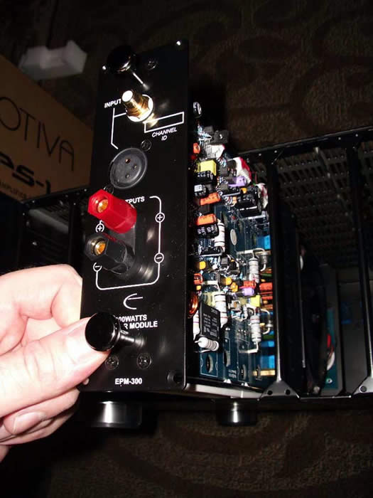
Inputs and Outputs
The Emotiva MPS-1 comes with all of the connections any audiophile would need as
far as amplifiers are concerned.
It is important to note that very few 7CH amplifiers in this
price class sport both balanced and unbalanced line level connections, not to mention a fully
functional trigger that is selectable for music or 12V detection.
The power receptacle is a two
prong job, which will likely suffer less ill effects of ground loops when installed in systems with a
poor earth grounds or miscellaneous components that utilize earth ground reference.
 I was a bit stunned when the UPS guy showed up with three boxes labeled
Emotiva.
How could this be?
Well, one box was for the card cage, another for five amplifier modules
and one smaller box for the remaining two amplifier modules.
All of the amplifier modules were individually packaged in their own
boxes (total of 11 boxes) and sealed with plastic wrapping.
Talk about careful packaging!
Emotiva spared no expenses here.
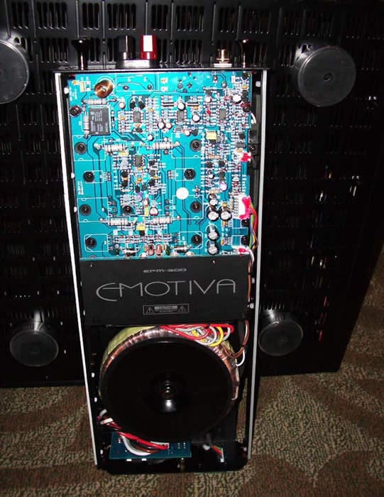
I soon found my way through all the packaging and quickly pulled one of
the amplifier modules out for a closer look.
What an impressive sight it was.
An oversized toroid power transformer, a big capacitor bank, and well
laid out circuit topology seemed apparent.
I noticed a thin plastic film over the front of the card that connects
to the chassis.
This was meant to protect the contacts from dust or debris.
Make sure you remove this thin plastic film from each amplifier module
before installing them into the card cage otherwise none of the LED
logic will work and you will be stuck with an amp with only a yellow
illumination from the Emotiva power button to give you visual
indication that the unit is working.
You don't want to make this mistake after loading up all seven modules,
cabling and placing this 115lb monster into your rack.
I was a bit stunned when the UPS guy showed up with three boxes labeled
Emotiva.
How could this be?
Well, one box was for the card cage, another for five amplifier modules
and one smaller box for the remaining two amplifier modules.
All of the amplifier modules were individually packaged in their own
boxes (total of 11 boxes) and sealed with plastic wrapping.
Talk about careful packaging!
Emotiva spared no expenses here.
I soon found my way through all the packaging and quickly pulled one of
the amplifier modules out for a closer look.
What an impressive sight it was.
An oversized toroid power transformer, a big capacitor bank, and well
laid out circuit topology seemed apparent.
I noticed a thin plastic film over the front of the card that connects
to the chassis.
This was meant to protect the contacts from dust or debris.
Make sure you remove this thin plastic film from each amplifier module
before installing them into the card cage otherwise none of the LED
logic will work and you will be stuck with an amp with only a yellow
illumination from the Emotiva power button to give you visual
indication that the unit is working.
You don't want to make this mistake after loading up all seven modules,
cabling and placing this 115lb monster into your rack.
 The Emotiva MPS-1 is certainly the most unusual amplifier I have
had the pleasure of reviewing.
Its card cage design brought me back to my telcom days when I was
designing DSL modem cards that were to be inserted into huge DSLAM
cages at the telephone companies.
The advantage here was having all of your technology in one location as
a central demarcation point for control and configurability, while at
the same time being more space and energy efficient.
I never really considered applying this type of solution into a
multi-channel amp, but after doing some thinking, I was glad somebody
did.
Too bad it wasn't me
The Emotiva MPS-1 is certainly the most unusual amplifier I have
had the pleasure of reviewing.
Its card cage design brought me back to my telcom days when I was
designing DSL modem cards that were to be inserted into huge DSLAM
cages at the telephone companies.
The advantage here was having all of your technology in one location as
a central demarcation point for control and configurability, while at
the same time being more space and energy efficient.
I never really considered applying this type of solution into a
multi-channel amp, but after doing some thinking, I was glad somebody
did.
Too bad it wasn't me
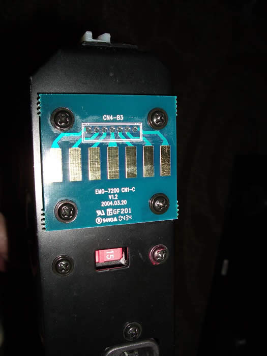
The MPS-1 card cage housing was manufactured as a sturdy metal case with a backplate
that connects power and logic to each mono block amplifier.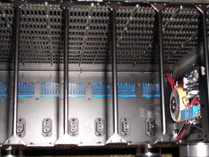
The power supply and circuitry to the right is for maintaining the front panel display and supporting the LED logic. Blue LEDs indicate normal operation for each amplifier module, while red indicates failure. Each amplifier module is optically isolated with 5 opto-coupled relays per module, making a grand total of 35 opto-coupled relays to ensure no ground loops or stray signal paths are present between each of the seven channels. Not since my telcom days of designing secure audio systems for NAOC and Air Force One have I seen such attention noise mitigation and ensuring the best possible channel to channel isolation.
Sliding in each amplifier module proved to be relatively easy thanks to the inclusion of slick nylon rails, but care must be observed while doing so.
Here are some guidelines to follow that I highly recommend: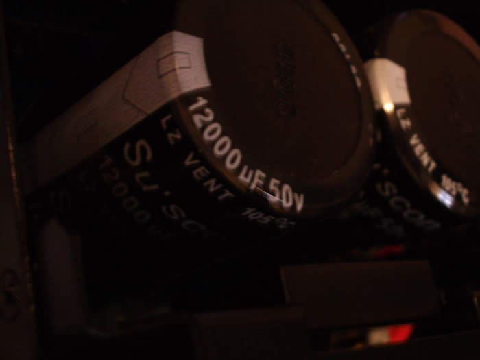
- Do not apply any pressure or stack any gear on the empty card chassis housing until all of the amplifier modules are loaded.
- Guide each module into the chassis with two hands to ensure they install smoothly and uniformly.
- Push each card into the chassis until you feel it lock into the power receptacle and then install the supplied mounting screws to keep them locked down.
After I had all of the power modules installed it was time to place the MPS-1 into my component rack. It was interesting to note that the individual models and card cage weight was very manageable. But, when the card cage was fully loaded, it became a bear to lift, topping my UPS shipping scale at 115lbs. If at all possible, installing the empty card cage in your rack before loading it with the amplifier modules would be most ideal. After making all of the necessary speaker level and line level connections, I was ready to roll.
Emotiva MPS-1 Measurement and Analysis - Part 1
I did some quick spot-checking on the MPS-1 amplifier gain structure to ensure it could be properly driven with a wide assortment of preamps or receivers. For unbalanced, I found the Voltage Gain (Av) to be 27.1dB while for balanced it was about 26dB. The Signal Detect Threshold of the "Music" trigger is about 1.7mVrms, which should work fine with most preamps/receivers including the Emotiva DMC-1. I found the 12V trigger to operate without issue for all of the receivers and processors I had on hand.
Editorial Note on Balanced vs Unbalanced:
I measured the voltage gain of the MPS-1 via balanced and unbalanced inputs and found the following:
- Unbalanced: Av = 27dB
- Balanced: AV = 26dB
- Typical THX Product
- Unbalanced Av = 29dB
- Balanced: Av = 23dB (6dB lower than balanced)
It's a standard practice in most consumer and pro audio equipment that the gain structure of unbalanced to balanced is about 6dB less for the latter for power amps. The preamp therefore usually has a +6dB boost via the balanced outputs to compensate. I was a bit puzzled that the MPS-1 didn't follow this convention. However I didn't find it to be much of an issue, especially since the balanced outputs were about 3dB hotter than convention. It took about 1.65Vrms to drive the MPS-1 to full power. Had the MPS-1 followed standard convention of Av = 23dB some preamp sections of receivers such as the Yamaha RX-V2500 may not have been able to drive it to full power since that receivers' preamp outputs clip when output signals exceed 2Vrms. My personal criteria for amplifier gain structure is that it should be able to hit full power when driven with 2-3Vrms. The MPS-1 fell well within this criteria.
Check out our Balanced vs. Unbalanced Connections Article for more information.
Editorial Note on Measuring Digital / Switching Amplifiers
The switching process of digital and multi-rail amplifiers, such as the Emotiva MPS-1, adds fast rising edges at the switching frequency to the audio output signal. These fast edges are of no consequence to the typical load, a loudspeaker, but present a difficult signal for measurement instruments. The fast switching edges present high energy content and will introduce slew rate limiting when presented to the input stage of most measurement instruments.
When stressed by these fast edges, the analyzer input amplifier will usually slew rate limit and will not be able to function effectively in its normal mode. Auto ranging will be affected and the signal under test will be misrepresented to the following measurement circuits.The result is that noise and distortion measurements of switching amplifiers with almost any analyzer without preconditioning will yield inaccurate and unpredictable results.
The solution to this problem is to precondition the signal before presentation to the analyzer. The way to do this is in the form of a low pass filter that will soften the fast edges while passing the primary audio signal intact. The best approach to this filter is a passive design, as it will handle the fast edges properly, is relatively low cost, and will not require power. A well-designed passive filter will also not compromise the audio signal passing through it by adding noise or distortion as an active design might. A passive design is also necessary to handle the wide dynamic range of signals that are normally presented to an analyzer. Any active filter has a limited amplitude range of operation. Thus, an active design would require an input attenuator and variable gain to accommodate the wide range of possible signal levels to be analyzed. Including such capability in an active design would be virtually duplicating the complete front end of the analyzer, an impractical approach from a cost and application point of view.
The Audio Precision AUX-0025 Switching Amplifier Measurement Filter is a dual channel multi-pole LRC passive filter that provides the necessary attenuation of out-of-band signals and reduces the steepness of the fast switching edges .We currently don't have this device and must conduct any measurements on digital and switch mode amplifiers with no passive filter. As a result, our distortion and SNR measurements may yield worse results than representative of the products under test. While the MPS-1 is not a "digital" or classic switch mode amplifier, we do believe its unique power supply topology, wide bandwidth design, and limiter circuit may affect the results of our tests and may decisively revist these measurements in the future with the addition of a LPF. Therefore we caution the reader to understand the limitations of our tests but will publish them nonetheless for a basis of which to compare once we have the proper filter networks in place. We also caution readers of other review publications to be mindful of this when evaluating their published measurements of these types of amplifier topologies, especially Class D / PWM type designs.
Power & Distortion Measurements
The frequency response was smooth and extended to a -3dB point of 125kHz.
At 1 watt into 8 ohms, the MPS-1 exhibited impressively low distortion (9.178+89.984)dBv = 99.2dBv or 100*alog^-1(-99.2/20) = 0.0011%
At 175wpc into an 8ohm load, we see the distortion rise, but again the amp switching effects contaminate the distortion measurement slightly. FFT analysis reveals (50.546+31.462)dBv = 82dBv or 100*alog^-1(-82/20) = 0.008% THD.
At 255wpc into a 4ohm load, we see the distortion rise, but despite the lack of the proper LPF implemented on our test setup, we still observe commendable results. FFT analysis reveals (30.097+47.28)dBv = 77.37dBv or 100*alog^-1(-54.85/20) = 0.014% THD.
I was able to achieve a maximum unclipped power of 175wpc into 8 ohms with Vin=1.65V Vout=37.39V unbalanced and about 255wpc into a 4 ohm load with Vin = 1.42V and Vout = 32V. Once I exceeded these measurements, the clamping circuit kicked in rounding off the signal and dramatically increasing distortion. Based on this, I would rate this amp to be a 175wpc into 8 ohms and 270wpc into 4 ohm, not 200wpc / 300wpc 8/4 ohm respectively like Emotiva rated in their literature.
When I informed Emotiva on my findings, they suggested that my test conditions were preventing me from achieving their published ratings due to line voltage sag. I respectively disagree since I was only testing one channel and monitored my line voltage to be a constant 124Vrms throughout the entire test. In addition, this was the first amp I tested that did not meet its power specification. However, please note this is also the first amplifier I tested with a thoughtful limiter circuit which does make it a bit tricky to accurately test.
I asked Emotiva to furnish their power measurements for this review as displayed below.
From Emotiva Engineering Labs:
According to Emotiva, this measurement was taken at 4 ohms (1% purely resistive load) and with a line voltage of 120V ac (1KHz input frequency). In this graph you can see they achieved 300W at 1% THD. Though my contention here was they were using an automated script in Audio Precision to find maximum power of the amplifier whereas my tests were using continuous tones. What likely occurred here is their measurement captured the power of the amplifier before the clamping circuit kicked in and limited the power output. This is a common measurement some publications use which I don't really like for that very reason. I like seeing steady state full bandwidth power response to see what the amp is really doing.
Despite that I was unable to measure their claimed power, I still believe maximum power ratings should be specified as unclipped ( usually 0.1% THD or less) not 1% which can clearly be audible and seen on an oscilloscope as a clipped waveform. For more information on our abilities to discern audible distortion, we recommend reading our Human Hearing Article Series.
In any event, I never found the Emotiva MPS-1 to be lacking in power or dynamics. I suggest not getting too caught up in power games since in most cases only a fraction of the amplifier power will ever be utilized under real world listening conditions.
Emotiva MPS-1 Measurement and Analysis - Part 2
Amplifier Output Impedance & Damping Factor Measurements
Amplifier output impedance when the MPS-1 was driving an 8 ohm load at 1 watt was below 140mohm from 20Hz to 20kHz. This is a very good measurement.
Damping factor was greater than 50 and remained linear for full audio bandwidth.
The true test is how well an amp will hold up into low impedance loads. Ideally an amplifier should act like an ideal voltage source, meaning power will double as load impedance halves since output voltage will remain constant. In order to do this, the amplifier output impedance must maintain a low enough level to not be the limiting factor.
As you can see, the output impedance is very similar (actually better) to the 8 ohm 1 watt test! Perhaps what's most impressive about the MPS-1's drive capability is its output impedance composure when driven at full power. Many lesser designed amps fall apart here, especially into 4 ohm loads. The MPS-1 sails by with vanishingly low output impedance, very similar for 4 and 8 ohm load impedances.
There is no substitute for good old fashion amplifier design with plenty of power devices to maintain a low output impedance, an ample power supply to keep the source resistance low and in the Emotiva case, a well executed switching topology to ensure high efficiency to minimize heat dissipation and maximize power transfer to the loudspeaker.
Amplifier Damping Factor 8/4 ohm Full Power
Damping factor remained stable and uniform at full unclipped power into an 8 ohm and 4 ohm load. Based on the principle of voltage divider, we see roughly ½ the damping factor for the 4 ohm load, but this was close to our minimum recommendation of 50. For more information on this topic, read our article on Damping Factor: Effects on System Response .
Signal to Noise Ratio (SNR) Measurements
Measuring the Signal
to Noise ratio of this amplifier proved to be quite challenging due to the lack of proper LPF for
limiting the bandwidth to below the switching frequency.
By applying A-weighting response curve, I was able to achieve partially reasonable measurements of 82dBA (A-wt) at 1 watt or about 102dBA at 270wpc.
From Emotiva Engineering Labs: We perform my signal to noise ratio test a little different than you do. We base our measurement strictly on the rms voltage as measured on the AP with a < 10Hz to 30Hz bandwidth selected. No other weighting is applied. The amplifier is connecting to a purely resistive load, in this case 4 ohms. We measured a noise floor voltage of 268uV using the balanced output of the AP with a 50 ohm output impedance - generator selected to off to terminate the input to the amplifier. From this starting point we let the AP do all the work. We select the output level from which I want the S/N ratio to be referenced at and call that the 0dB point. Below are some measurements we have taken:
- 102dB ref 300W
- 101dB ref 270W
- 87 dB ref 10W
- 77dB ref 1W
These numbers should be more consistent with what you are hearing from the amplifier. Also, we believe these numbers represent a best case scenario because we are using the balanced input. The key to this test is the noise floor of the amplifier. This can change significantly if power cables are inducing 60Hz into signal, other equipment could be radiating noise, etc.
In any event, the 77dB @ 1 watt number isn't flattering to say the least, but given the unique amplifier topology, I suspect the out of band switching noise is producing a non representative number since noise was never an audible issue in real world listening tests. When using the Yamaha RX-V2500 as the preamp for the Emotiva MPS-1, the set-up was dead quiet and sounded as silent as other amps I have measured with significantly lower noise floors.
Emotiva MPS-1 Listening Tests and Conclusion
I tested this amplifier both in my reference system, and even toted it over to my wife's aunt and uncle's home where they throw the absolute best parties. For those who never partied with Columbians I can tell you it's quite an extravaganza of loud music, dance, excellent food and drink.
For use in this large party room environment, this powerful, yet power and space efficient multi-channel amplifier was complimenting a Yamaha RX-V2500 receiver (which when used as a pre/pro is absolutely phenomenal).
By testing the Emotiva MPS-1 in two completely different environments and applications I was able to see how it performed under a myriad of circumstances:
- Environment #1: My Reference System - A pristine environment with moderate to high SPL levels in a medium sized living room designed for more focus on detail and sound quality.
- Environment #2: Aunt/Uncle Party Room - Ultra-high SPL levels set for high impact sound for a huge 50' room. The speaker system used is similar to my Reference System but with two extra RBH-1010 subwoofer modules - transforming the front speakers into the RBH T-3 Signature System.
I have always been of the viewpoint that sonic differences between well-designed amplifiers are very difficult to discern, provided that they are operated in their linear operating region. Get the output impedance and noise floor low enough, and the amplifier will generally not hiccup at any speaker load, allowing it to be removed from the sonic chain of the system. That being said, I was eager to find out if the Emotiva MPS-1 was able to achieve the sonic bliss of a traditional Class A/B amplifier since to date I hadn't heard a switching, or in this case, rail tracking amp that could.
SACD: Patricia Barber Café Blue
This SACD remains one of my benchmark discs for good reason - lumpy
jazz in a smooth jazz environment.
You won't find repetitive and annoying saxophone scales, single stroke
drumming, and simplistic guitar rifts. Instead you're showered with
snappy jazz and provocative lyrics, slamming drums and memorable
instrumental solos. The SACD layer of Track #2, "Morning Grace" sounded
excellent on my reference system.
The stereo separation was most impressive.
In fact there were times where I believed the imaging of my speakers sounded better than ever on this amp and I couldn't help to wonder if it had to do with the excellent channel to channel isolation bestowed upon the mono block design approach.
SACD: Patricia Barber Modern Cool
I put in another reference disc, which again happens to be a Patricia Barber
Modern Cool
from Premonition Records.
If you really want to show off your system's
dynamics capabilities, this is a must have disc.
Track#7 "Company" will reward time after time,
especially during the explosive drum solo half way into the song.
Wimpy speakers dare not play
this track, and the same applies for flea watt amps.
The MPS-1 really shined with this recording
and was able to drive my reference system as well as the best gear I have had the fortune of
reviewing.
The bass was well pronounced, the noise floor commendably low, and the soundstage wide
and open as it should be.
DVD-Audio:
Blue Man Group The Complex
Given the fact that the MPS-1 is a full mono block design with
independent power supplies for each channel, it was safe to assume if
this amp performed well in two-channel, it should perform equally well
in multi-channel applications.
I tested this assumption with a very demanding and well recorded DVD-A
disc from the Blue Man Group.
I am a sucker for instrumentals, especially those emphasizing drum solos. The multi-channel DTS DVD Audio disc of Blue Man Group - The Complex is a shining example of such a recording. Track#3 on the DVD-A layer featuring Dave Matthews is a killer sounding song and is even cooler on the DTS side since you get to see the Blue Man Group in action spraying paint on each other, playing unconventional instruments, and watching the world around Dave Matthews transform between reality and cartoon. Very cool indeed. Track #1 jumps right out at you and gives your system quite a workout.
The MPS-1 again delivered with flying colors. Every paint-splashing, whip-whooshing sound was rendered with excellent clarity, while Dave Matthews' voice remained focused and articulate without any noticeable sibilance.
Listening Torture Test - The Columbian Party Extravaganza
 It was obvious that the Emotiva MPS-1
delivered performance as promised when installed in my primary reference system.
Now it was time
for the true torture test.
Could this amp perform in a huge room for loud Colombian
parties?
It was soon time to find out as I wired the amp into my Uncle's system in preparation
for their next fiesta.
It was obvious that the Emotiva MPS-1
delivered performance as promised when installed in my primary reference system.
Now it was time
for the true torture test.
Could this amp perform in a huge room for loud Colombian
parties?
It was soon time to find out as I wired the amp into my Uncle's system in preparation
for their next fiesta.
As the night wore on, the room was filled with more people, and the more they drank, the louder the music was turned up. Of course, I have no tolerance for blatantly loud music and I was fortunate to have my trusty but not so aesthetically pleasing orange ear plugs installed. I estimated they were hitting SPL levels in excess of 120dB - at least until the MPS-1 went into protection mode and shut down. This happened a few times during the course of the evening and I was curious as to why, since I heard no signs of distress from the amp, even at these insane levels.
Later on the bench I discovered that the MPS-1 was engaging its soft clipping circuit at around 37-38Vrms into 8 ohm loads and while driving 4 ohm loads the MPS-1 delivered about 31Vrms into 4 ohm load unclipped (note the RBH T-2 System has 4 ohms impedance). However, as I increased the signal level just below clipping, I was able to achieve 33Vrms at 1kHz but the amp shut off when frequency was brought down below 60Hz. It was apparent the sensitivity of the soft clipping circuit / limiter needed some tweaking. I informed Emotiva of my findings and they quickly resolved this issue, sent me a new sample and I didn't observe this problem thereafter.
The next round of Colombian parties ran smoothly as they blasted the tunes till their hearts were content (and ears all but fried). I was most impressed with the power delivery of the MPS-1 and its composure on some of the most rigid torture tests I have ever had the pleasure of inflicting upon an amplifier.
CD: Calos Vives Dejame Entrar
Some of the more popular latino music at these parties included Carlos
Vives and Jaunes for example.
Carlos Vives "Déjame Entrar" is the type of song that puts you in that
party and dance mode. PLIIx Music Mode, expanded the sound field so
immensely that it just begged to be played louder. To really belt it
out to the people, I switched over to 7CH stereo mode and rocked the
house.
I actually found a point of insane loudness where some of the party-goers' facial expressions actually peered at me with a hint of "excess". Alas this system met their requirements and the Emotiva MPS-1 was the legendary center piece for achieving this realization.
Conclusion
The Emotiva MPS-1 is truly an excellent multi-channel amplifier regardless of price. It has an audiophile sonic signature and appearance to appease the serious music aficionado and home theater enthusiast, with enough power reserves to quench even the hardest partying crowds - the Colombians. The MPS-1 is the first rail tracking amp I have heard that I really liked. I felt nothing in the sonic signature to be disappointing and after the limiter fix, never found it to be lacking in power. Its no-nonsense build quality and choice of heavy-duty parts makes it an unprecedented value. You get a sense of real pride of ownership with this product, not only because of its stellar sound quality, but also because of its most attractive packaging, form, fit and function.
In situations demanding high power, quality sound on a budget, tight spacing requirements, and limited airflow, I can think of no better seven-channel amplifier than the MPS-1. While it's a bit more labor intensive to set-up than a typical all-inclusive design, its design execution is brilliant in terms of serviceability and upgrades. If one module should fail, the installer can simply replace it rather than take the entire system down. Should the end user require more channels of amplification, Emotiva will soon be releasing 100wpc stereo channel modules. This will allow for up to 14 channels of amplification in the same chassis or any permutation of 1CH and 2CH power modules depending on your needs. Very cool - literally!
The Score Card
The scoring below is based on each piece of equipment doing the duty it is designed for. The numbers are weighed heavily with respect to the individual cost of each unit, thus giving a rating roughly equal to:
Performance × Price Factor/Value = Rating
Audioholics.com note: The ratings indicated below are based on subjective listening and objective testing of the product in question. The rating scale is based on performance/value ratio. If you notice better performing products in future reviews that have lower numbers in certain areas, be aware that the value factor is most likely the culprit. Other Audioholics reviewers may rate products solely based on performance, and each reviewer has his/her own system for ratings.
Audioholics Rating Scale
 — Excellent
- — Very Good
- — Good
- — Fair
- — Poor
| Metric | Rating |
|---|---|
| Frequency Response Linearity | |
| SNR | |
| Output Impedance | |
| Measured Power (8-ohms) | |
| Measured Power (4-ohms) | |
| Multi-channel Audio Performance | |
| Two-channel Audio Performance | |
| Build Quality | |
| Fit and Finish | |
| Ergonomics & Usability | |
| Features | |
| Performance | |
| Value |
Gene manages this organization, establishes relations with manufacturers and keeps Audioholics a well oiled machine. His goal is to educate about home theater and develop more standards in the industry to eliminate consumer confusion clouded by industry snake oil.
View full profile