
RealTraps MiniTraps MicroTraps MondoTraps Review
RealTraps MondoTrap
- Product Name: RealTraps
- Manufacturer: MondoTrap
- Performance Rating:

- Value Rating:
- Review Date: January 05, 2006 18:00
- MSRP: $ 139 and up
MicroTraps:
Absorption
for mid/high frequencies
H x W x
D: 2' x 4' x 1 1/4"
Weight: 8lbs
MiniTraps:
Absorption
for low frequencies
H x W x
D: 2' x 2' x 3 1/4", 2' x 4' x 3 1/4"
Weight: 9 lbs, 18 lbs
MondoTraps:
Enhanced
absorption for low frequencies
H x W x
D: 2' x 4'9" x 4"
Weight: 28lbs
Pros
- As attractive as acoustic panels can be.
- Available in three colors.
- Ease of assembly.
- Selection of traps to suit purpose.
- Class A fire rating.
Cons
- Expensive.
- Potential consumption of floor space.
- WAF (Wife Acceptance Factor).
RealTraps MiniTraps MicroTraps MondoTraps Introduction
The room is the first thing we start with and the last thing we think about (1). How true is that for the vast majority of us? And yet it is all the more surprising given that each person reading these words counts sound quality of fundamental importance to them.
In all rooms, sound reaching the ears is comprised of a combination of direct sound from the source and reflected sound that has bounced off one or more of the room's walls. Why is this important? Because in an untreated room, approximately 50% of sound heard at the listening position is comprised of the latter(2), and given its magnitude it is therefore no exaggeration to state that a room should be considered the biggest single contributor to high fidelity sound reproduction, and which consequently can make or break the quality of sound that we hear.
The goal of room treatment is not to reduce reflected sound to zero; that would result in a room equaled in its sonic accuracy only by how dead it sounded and in any event would be totally impractical for all but anechoic testing chambers. Instead, room treatment aims to increase the ratio of direct to reflected sound and in doing so flatten the frequency response as far as is practically possible whilst retaining the liveness that reflected sound adds to a room.
RealTraps MiniTraps MicroTraps MondoTraps Overview
Room treatment maybe accomplished by a variety of means and one of the most effective is by absorption. Simply put, acoustic absorption works by causing sound to be exchanged for heat through friction between the material's fibers as they vibrate in sympathy with the energy in the air. As sound progressively permeates the absorptive material, ever more energy is lost to this process and the aforementioned ratio correspondingly increases.
When treating one's room with absorption, two routes are available:
- DIY absorption.
- Commercially manufactured absorption.
A fellow Audioholics member took the DIY route and in doing so provided others the invaluable opportunity to see, if not hear the difference room treatment makes. By the project's culmination(3), I knew that I too wanted a piece of the action, but was unsure whether to opt for the DIY route or the more costly but potentially more effective alternative route of commercially manufactured absorption. Ultimately, my decision came down to not wanting to take the DIY route, finding myself amazed by its results and then thinking 舠 I wish I had just spent that bit more and got even better results with commercially manufactured absorption". I chose the latter route.
RealTraps
I am not usually one to buy just 'good enough'. When it comes to things I am serious about, I always buy the best I can afford. Regular visitors to the Room Acoustics, System Layout & Setup Forum at Audioholics will know Ethan Winer as someone who frequently yet selflessly gives demonstrably good advice to others. For this reason above any other (though after seeing some of the alternative products commercially available it's little wonder) I decided that I'd buy either from RealTraps, Ethan's company, or not at all. Ultimately I did buy, and went with four 2' x 2' MiniTraps, the Mondo Room Kit which comprises four 4' x 2' MondoTraps, four 4' x 2' MiniTraps and three 4' x 2' MicroTraps, and six stands. Note that the difference between MicroTraps, MiniTraps and MondoTraps is principally one of panel thickness, these being 1 ¼", 3 ¼" and 4" respectively.
 If
you're lucky enough to live within driving distance from the company's factory in Wallingford,
Connecticut, traps maybe picked up in person. For those like myself less fortunate, they can usually be
shipped either to the nearest airport or delivered direct to the door for an additional
surcharge.
If
you're lucky enough to live within driving distance from the company's factory in Wallingford,
Connecticut, traps maybe picked up in person. For those like myself less fortunate, they can usually be
shipped either to the nearest airport or delivered direct to the door for an additional
surcharge.
After collecting the traps from the airport and getting them home the fun began! First impressions were
good; the traps came in robust cardboard boxes and were internally spaced from sides and corners to
prevent damage in transit. Stands were assembled quickly and easily with eight screws, the procedure
intuitive. Multiple holes in the stand's legs allow vertical adjustment of panels by up to 18".
After picking an arbitrary position, the four MondoTraps and two of the MicroTraps (the third MicroTrap envisaged hung from the ceiling) were attached to stands by a further four screws each. All screws are included with stands.
Unique to the 2' x 2' MiniTraps, a 6" spring is included which allows them to be mounted as originally intended in the tri-corner formed by two of a room's walls and its ceiling.
RealTraps MiniTraps MicroTraps MondoTraps Setup, Measurement, and Analysis
There really is no getting away from having to experiment with trap/speaker placement and listening position to obtain an optimal room response. Thankfully, this iterative process can be shortened somewhat, beginning by placing MicroTraps at the first-reflection positions and MiniTraps and MondoTraps straddling wall/wall, wall/ceiling and wall/floor corners, thus achieving the greatest absorption. Unfortunately, door and/or window placement in many peoples' rooms may make placing traps in some of these locations impractical.
What are first reflections and how do I calculate their positions?
Early, or first-reflections arrive at the ear after direct sound having reflected from a surface between the speakers and listener. By placing absorption at the reflection position, the sound is intercepted and resisted against traveling any further, thereby increasing the proportion of direct to reflected sound heard at the listening position and thus improving stereo imaging. To find the first-reflection position for a given speaker, sit at the listening position and have someone slide a mirror along a wall until you see the speaker's tweeter in the reflection. This marks the position where absorption for that speaker should be placed. Other positions to be treated include the floor and ceiling.
Take my own room for example. It has three full-height glass windows along one wall, a double-width door opening along the opposite, bare walls and wood-laminate flooring. Straddling the full-height glass window wall/ceiling corner with traps was simply out of the question.
Then there's the aesthetic factor. The traps maybe attractive in their own right, but my own feeling was still to maximize placement behind the listening position because I felt that a greater proportion of two-channel sound would be absorbed by the traps in its first pass by me. Placing traps primarily behind the listening position also ensured most of the front wall remained non-distracting to the eye and more importantly; free to project films upon.
Finally, my room is square in plan. After a cube, acoustically speaking it's the worst shape there is! If ever there was a challenge for the traps, my room surely would be it.
Measurement
On the recommendation of others, I used Acoustisoft's comprehensive acoustic measurement program ETF along with the analogue version of RadioShack's inexpensive yet indispensable SPL meter.
ETF is a relatively easy to use program that sends out a full-range, i.e. 20Hz to 20kHz, frequency sweep over a five second period from a personal computer's line output hooked-up to a hi-fi before processing the response as-measured by a microphone placed at the listening position and hooked-up to the computer's line input. In my particular case, measuring was performed with the goal of achieving optimal two-channel sound, so only the front two towers were used.
After taking a plethora of measurements having incrementally moved the speakers back, forward, and sideways, toed-in and out, the couch drawn forwards and pushed backward, and the traps moved correspondingly to suit; in short, every speaker/couch/trap combination known to man, then analyzing and comparing results, I finally settled for the following trap layout:
- One MondoTrap placed in each of the room's four vertical corners.
- One 2'×2' MiniTrap placed above each MondoTrap.
- One MicroTrap at the left tower's side first-reflection position with the remaining two hung from both towers' ceiling first-reflection positions.
- Two 2'×4' MiniTraps additionally placed in the room's rear corners with the remaining two lain horizontally along, but spaced from the rear wall.
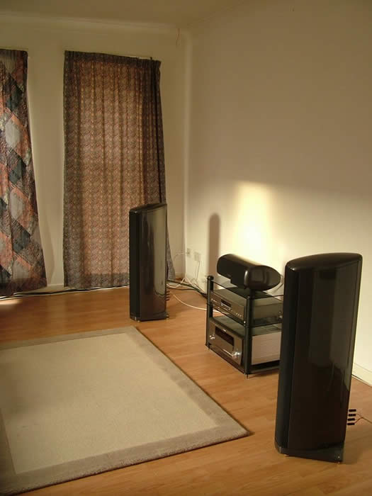
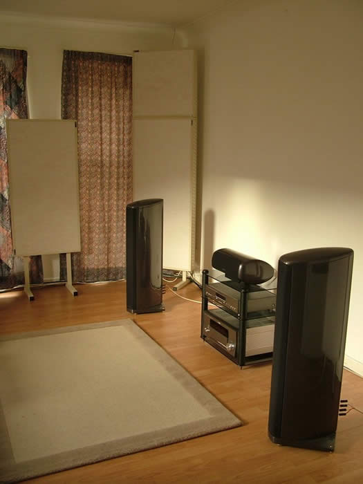
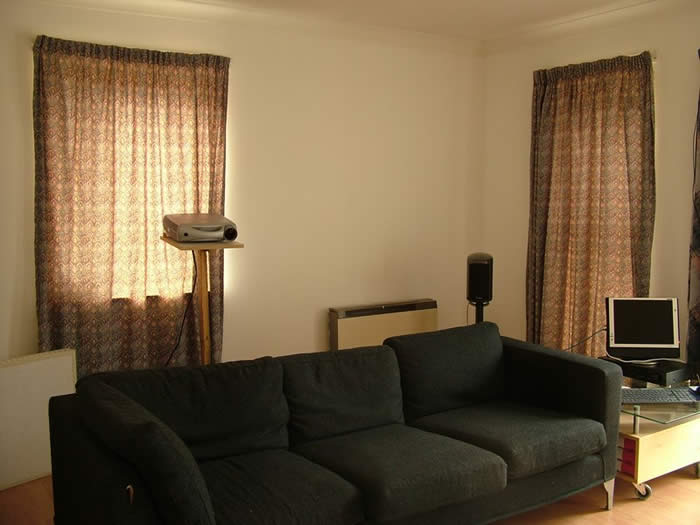
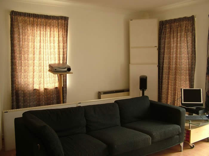
Before/after photos of the untreated/treated front/back of the room
Note that the front-right tower's side first-reflection position was left untreated because I felt that with the double-width door opening more or less occupying this spot, thereby allowing sound at least partially to escape out the room, it would be more beneficial to hang two MicroTraps from the ceiling instead of just one.
Analysis
Being a website that prides itself on the dissemination of factual information, an Audioholics review just wouldn't be the same without data to backup its findings.
In order to legitimately be able to compare results of the room both treated and untreated, compatibility had to exist between the two sets of measurements. This was achieved by re-measuring the untreated room unchanged in any way from the treated room except for having removed all traps. Whilst this necessitated obtaining results in treated/untreated order, to permit a before/after comparison they are presented here reverse to this.
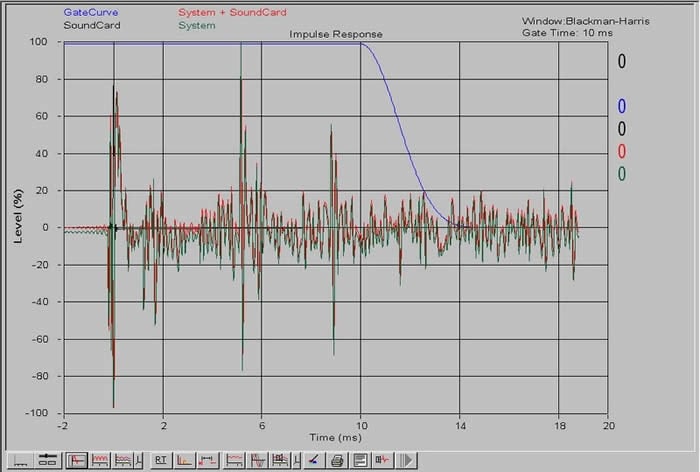
The response to the test signal sent out by
ETF is known as the
impulse response
and all results offered by the program are calculated
from it. The impulse response is however itself helpful because it indicates the presence of high
frequency (more so than mid or low frequency) reflections which easily are recognized as prominent
spikes(4).
Because MicroTraps are specifically designed to absorb high frequencies, it makes sense why placing them at the side and ceiling's first-reflection positions has resulted in the reflections at approximately 5.3 and 8.8ms being tamed and the response improved overall. Using these values to calculate the difference in path length of the reflected sound from the direct sound confirmed that the reflections were indeed due to the ceiling and side walls. As for the floor's first-reflection positions, since placing traps there would be impractical, a rug was laid instead.
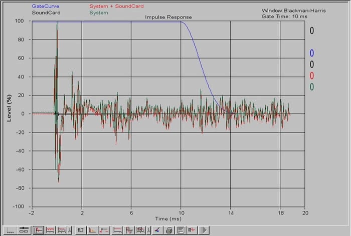
What's the connection between ms and distance?
Since reflected sound travels a greater distance than direct sound, it follows that it must take longer to reach the ears. By taking the product of the speed of sound (343m/s) and the horizontal ordinate (ms) of a spike on an impulse response, a value representing the difference between the reflected sound and direct sound path length is returned. An impulse response is therefore invaluable in firstly determining where absorbtion is required, and subsequently in checking that placing it there has worked.
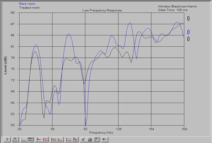
Low-frequency time-slice
The plot overlay shows a significant reduction in the null at approximately 90Hz and smoothing of the response overall. This two-dimensional plot is effectively taken at time t=0; a snapshot in time if you will. By contrast, waterfall plots show how frequency decays over time and are therefore more useful.
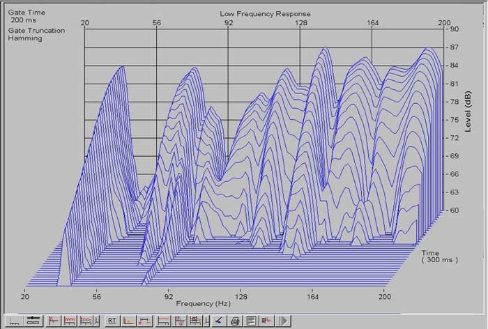
Low-frequency waterfall
On these plots, the traps have clearly reduced the blade-like response to one much smoother.
The large sharp peak centered around 38Hz was suspected of being a room mode by the fact that it extends significantly longer in time than the frequency response adjacent to it. A simple calculation placed the first axial mode for the room at 40Hz which clearly is very close to 38Hz, thereby confirming that this was indeed a room mode.
Here, the negative effect of having a room in which two of its three dimensions are identical maybe seen, as standing waves in one direction simultaneously occur in another. This helps explain why rooms with dissimilar dimensions are geometrically acoustically better than those without.
Whilst the peak's presence is almost certainly due to the listening positions relatively close proximity to the room's centre (the first axial mode in any direction always occurs halfway between two parallel surfaces), unfortunately little could be done about it after both the couch and speakers were drawn away from their respective rear walls to reduce the effects of comb filtering.
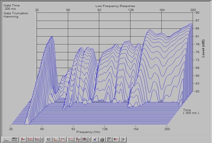
Treated room L.F. waterfall
Overall, more work is required in this region. I can't help but feel that the relatively small size (4.3×4.3m) and shape of my room make taming the low-frequency response more difficult than would perhaps be the case in a larger non-square room. However, by integrating my sub (crossed at 80Hz) with my towers, it should be possible to further improve upon the above low-frequency response due to the sub's larger, more capable driver than those of the towers, and the far greater number of placement locations available to it.
What are room modes and how do I calculate them?
Room modes are natural frequencies of vibration whose value is a function of the room's dimensions. The wavelengths of axial modes are an integer multiple of the distance between two of the room's walls and cause standing waves which are heard as an increased loudness and swelling of sound. Axial room modes maybe calculated from the expression 343n/2L where 343 is the speed of sound in meters per second, n is an integer indicating the mode under consideration and L is the room dimension in meters in the applicable direction. For example, substituting 2 for n and 4.3 for L would return the 2nd axial mode for a room whose dimension in the direction being considered was 4.3m.
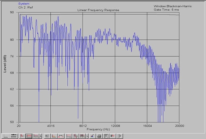
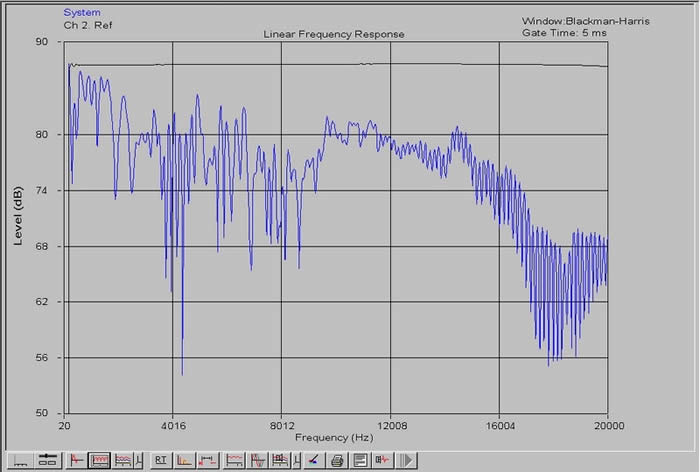
Full-range frequency response
Here you can see the reduction in comb filtering (jaggedness) the traps have made. Comb filtering results from the combining of direct and reflected sound and has a negative effect on stereo imaging. Its effect is most pronounced the closer one is to a room's walls and this is one reason why the listening position should be drawn away from them.
RT-60 time
The RT-60 time is the time taken for sound to decay by 60dB which by then would typically be inaudible. Assigning a value to an ideal RT-60 time for a small room is somewhat awkward given that certain types of music are naturally better suited to large rooms with longer RT-60 times than small rooms with shorter RT-60 times. Ultimately, the best that can be hoped for is to achieve some kind of average value and in this respect it has been found that a time of approximately 0.3 to 0.39 seconds is desirable(5, 6).
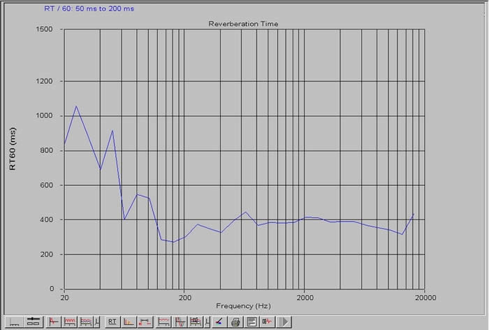
Note that from approximately 200Hz and below, the results of ETF are not meaningful with regard to small room acoustics and should therefore be ignored(6).
As may be seen, whereas the untreated room's RT-60 time of 0.4 seconds lay at the upper-bound value of the aforementioned range, the introduction of traps has clearly reduced this to closer to 0.3 seconds and over a small portion of the frequency range, closer to 0.2 seconds, which one could expect to find in a recording studio where near-field listening reduces the effects of the room on what is heard(6).
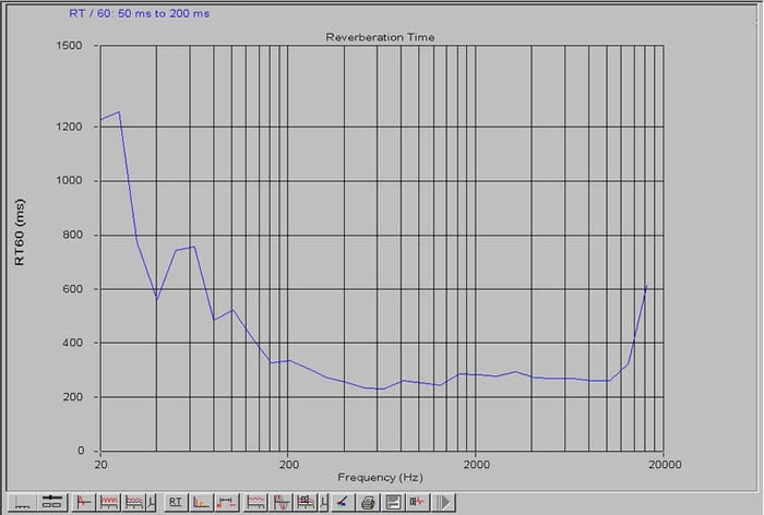
The treated room's slightly lower than perhaps ideal value for the RT-60 time may be due in part to the relative close proximity of the listening position to the speakers. However, even after drawing the speakers and listening position away from the room's walls to minimize comb filtering and other boundary effects, the 'golden rule' of placing the listening position between 1-1.5 times the distance between the speakers from the speakers was preserved.
RealTraps MiniTraps MicroTraps MondoTraps Listening Tests and Conclusion
Measuring and analyzing data is a worthwhile and hopefully rewarding experience, but there comes a point when you realize that to the best of your abilities you've done all that you can to optimize the room's response and that the time has come to sit down, relax, and listen. Listening of course is an entirely subjective experience, but for what it's worth, here are my thoughts:
Two-Channel CD
I'll be honest. All things considered, I believed my room sounded pretty good untreated. But listening to Brenda Russell's Piano in the dark , The might of Rome from Gladiator, End of the day by The Lighthouse Family and a real favorite of mine; Speedway at Nazareth from Sailing to Philadelphia by Mark Knopfler, I simply couldn't get over the utterly captivating sound and unprecedented level of detail I was hearing. The stereo image was so clear and precise, bass wonderfully tight and cymbals biting sharp; I just sat there shaking my head in wonder. Whereas before the room was treated I would sometimes pick out sounds buried deep within the music, now I find myself able to pick a sound out and follow it through an entire song, as transparent as the music now is.
I really could go on and on, but won't because the more time I spend writing, the less time I spend listening! Ultimately, my experience with RealTraps can be summed up by saying that I am more or less rediscovering my entire music collection all over again, and believe me when I say that it's never been such a pleasure.
Suggestions for Improvement
It really is difficult to find anything wrong with RealTraps as the product has clearly been well thought out from concept through design to manufacture. I have only one suggestion which I feel might increase the product's adaptability:
At present, the spacing of hole centers of the stands prohibit fixing 2' x 4' panels horizontally. If this were revised and the hole centers spaced such that an additional 2' x 4' panel could be fixed horizontally, one above the other, a 4' x 4' panel formed from two 2' x 4' panels for increased side first-reflection absorption coverage would then be possible.
Conclusions and Overall Perceptions
There is a growing awareness of the fundamental importance of room acoustics to the audio enthusiast and rightly so. In a treated room, it rapidly becomes apparent that even modestly priced speakers can sound excellent. But, in an untreated room, a flagship pair of speakers will to an extent be wasted as the room negatively impacts unchecked upon the sound leaving them.
Is it really worth debating the audible differences, if any, between components whose distortion is measured in fractions of one percent when by comparison rooms commonly cause large peaks and enormous nulls to appear over a disproportionately important region of the frequency response? Let's get our priorities in order.
Absorption wont by itself deliver a ruler-flat frequency response. Neither will it cure all of a room's ills. But what it will do is significantly improve stereo imaging, clarity and definition far beyond what could ever be expected or achieved from upgrading any other component, and yes, that includes even speakers. Pound for pound, absorption will almost certainly return the greatest audible improvement you'll ever likely hear.
The room maybe the first thing we start with and the last thing we think about, but better to think about it late than never. If you are genuinely serious about improving your sound, you owe it to yourself to check RealTraps out. Highly recommended.
Associated Test Gear
|
Hardware |
Description |
|
Yamaha (http://www.yamaha.co.uk/) DSP-Z9 |
A/V Amplifier |
|
Sony (http://www.sony.co.uk/) VAIO PCV-V1/G |
Personal Computer |
|
RadioShack (http://www.radioshack.com/home/index.jsp) SPL meter |
Analogue SPL meter |
|
Mission (http://www.mission.co.uk/) Elegante e82 Tower Loudspeakers |
Front two speakers |
|
ETF (http://www.acoustisoft.com/) |
Acoustic measurement software |
The Score Card
The scoring below is based on each piece of equipment doing the duty it is designed for. The numbers are weighed heavily with respect to the individual cost of each unit, thus giving a rating roughly equal to:
Performance × Price Factor/Value = Rating
Audioholics.com note: The ratings indicated below are based on subjective listening and objective testing of the product in question. The rating scale is based on performance/value ratio. If you notice better performing products in future reviews that have lower numbers in certain areas, be aware that the value factor is most likely the culprit. Other Audioholics reviewers may rate products solely based on performance, and each reviewer has his/her own system for ratings.
Audioholics Rating Scale
 — Excellent
- — Very Good
- — Good
- — Fair
- — Poor
| Metric | Rating |
|---|---|
| Build Quality | |
| Ergonomics & Usability | |
| Performance | |
| Value |