
Understanding Ohm's Law, Impedance And Electrical Phase 101
The Greek Letter Omega, Symbol Of The Ohm
Introduction
Have you ever wondered what makes a loudspeaker “difficult to drive”? Do you wonder what’s so special about an amplifier that is stable into a 4 ohm load? If these are the kinds of questions that leave you mystified, this may be the article for you. Fortunately, there is nothing extraordinarily difficult involved in answering these questions: as long as you have rudimentary math skills and knowledge of the right equations, you will be able to look at a few basic measurements of a loudspeaker, namely the impedance curve, electrical phase curve, and voltage sensitivity, and determine what kind of amplification you’ll need to get the job done.
Terminology
Before we get too far, it’s important to define some terms:
-
Voltage: The difference in electrical potential between two points measured in volts (V); a measurement of the energy contained per unit of charge.
-
Current/Amperage: the total flow of electric charges through a surface at the rate of coulomb per time unit. The flow of current through a circuit is usually measured in amps (A) or milliamps (mA).
-
Resistance: Opposition to the flow of current through a conductor measured in ohms (Ω).
-
Capacitance: The ability to store an electrical charge measured in Farads (F) or micro Farads (uF).
-
Inductance: The property of a conductor in which a change in current flow within the conductor creates voltage within itself as well as other nearby conductors. Inductance is measured in Henries (H)
-
Impedance: Similar to resistance, impedance is the opposition of AC current flow through a conductor in a reactive circuit (i.e. one exhibiting elements of capacitance and inductance).
-
Phase Angle: The degree to which current flow will lead or lag the voltage waveform in a reactive circuit element.
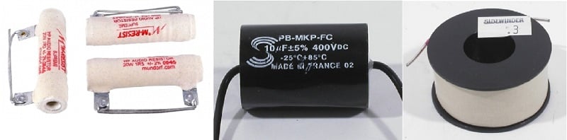
From left to right, a set of resistors, a capacitor, and an air core inductor.
Ohm's Law
To really kick things off, we will first want to examine Ohm’s Law; in plain English, the law says that the current flow/amperage through a conductor is directly proportional to the voltage potential, with the factor between them being the conductor’s resistance, or in the case of a complex circuit, its impedance. Mathematically, this is simply written as:
where V=Voltage, I=Current, and R=Resistance. In a complex load, we substitute Z for resistance, where Z=Impedance.
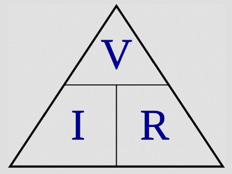
The Ohm’s Law Triangle demonstrates the interchangeability of the variables. The line dividing the left and right sections of the triangle represents multiplication; the line between the top and bottom sections represents division.
Active Power
One other important equation to keep in mind is:
P = V * I * COS(Ф) (2)
where P=Power and Ф (Phi) = phase angle. Looking at our prior equations, you’ll find you could also re-write this as:
P = I^2 * Z * COS(Ф) (3)
and
P = (V^2 / Z) * COS(Ф) (4)
It’s worth pointing out here that power will always be positive, given that it is proportional to the square of the current or voltage; that is to say, energy is always dissipated inside of an electrical circuit, though one may note inductance and capacitance in and of themselves store, but do not dissipate energy. With any luck, these equations haven’t scared you off just yet. Suffice it to say, a strong understanding of the relationships they represent are a key component to answering the questions at the beginning of this article.
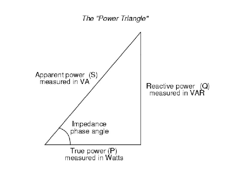
The Power Triangle visually demonstrates the power lost due to phase shift between voltage and amperage, and is given above as Reactive power.
The Application
So now that we know these rules exist, how do we apply them to audio? Well, let’s start with the magic number of 2.83 volts. You may see that number pop up in speaker specifications a lot with respect to voltage sensitivity. You’ll also find that the majority of loudspeakers are specified as an 8 ohm nominal load. Going back to equation (1), we can plug in 2.83 volts = X amperes * 8 ohms. To solve for X, we simply divide 2.83 by 8, which yields amperage as 0.354, and gives us the statement 2.83 volts = 0.354 amperes x 8 Ohms. Plugging those numbers into equation (2) to solve for power (and ignoring the phase angle for now), you’ll find that 2.83 volts translates into 1 watt with an 8 ohm load.
OK, what about 4 ohms? Well since the impedance is cut in half, you’re going to have to double the amperage to maintain the ratio, and you’ll get the formula 2.83 Volts = 0.708 Amperes x 4 Ohms. Because amperage goes up by a factor of two as a result of impedance being cut, power goes up by a factor of two as well, meaning that 2.83 volts equates to 2 watts into a 4 ohm load. That’s a pretty significant difference, and explains why a 4 ohm speaker is more demanding of an amplifier than an 8 ohm speaker of the same voltage sensitivity.
Now let’s take a look at what happens when you have an 8 ohm speaker with a voltage sensitivity 3dB less than a comparable 4 ohm speaker. In this example, the speakers will consume equal amounts of power to reach any given SPL; however, the voltage and amperage will be different, as the ratios are defined by the impedance. For example, 1 watt into 4 ohms equates to 2 volts and 0.5 amperes; as mentioned above, 1 watt into 8 ohms equates to 2.83 volts and 0.354 amperes. Looking at this, you’ll note that the 8 ohm load requires 41% greater voltage, but correspondingly less amperage relative to a 4 ohm load. Which is preferable depends on the capabilities of the amplification you’re employing; if you’ve got a meaty amplifier that is stable into low impedance loads, a 4 ohm load may not be a big problem. On the other hand, if you’re utilizing a low end surround receiver, you may wish to avoid the 4 ohm option, as the odds are they simply aren’t built with the demands of a 4 ohm load in mind.
High Sensitivity?
As one more example, let’s take the case of two speaker systems, one with a rated voltage sensitivity of 96dB w/ 2.83V at 1 meter, and the other rated at 90dB under the same circumstances. Let’s assume that the 96dB sensitive speaker dips down to the 3.2 ohm mark (the minimum for a 4 ohm nominal speaker per the IEC method, as well as the minimum allowed per THX Ultra 2 spec), whereas the 90dB sensitive speaker stays at 8 ohms or above. This scenario may not be as uncommon as you’d think: it’s easy to have higher sensitivity (and efficiency in terms of watts) at high frequencies; however, at lower frequencies where you must displace more air, you will tend to need more power to reach a given SPL. A few tricks can be used to help even out this mismatch and retain reasonably flat voltage sensitivity over a wide range of frequencies (i.e. a flat frequency response). One of those tricks is wiring a pair of woofers in parallel: this increases voltage sensitivity by 6dB over a single woofer, at the expense of halving impedance.
So what do the numbers tell us? To hit 96dB at 1 meter, our 90dB sensitive loudspeaker will require 4 watts into an 8 ohm load, or ~5.66 volts and ~0.71 amperes. On the other hand, our 96dB speaker will require 2.5 watts into a 3.2 ohm load, or ~2.83 volts and ~0.88 amperes. Surprisingly, in spite of the rather significant advantage in voltage sensitivity, the 96dB sensitive loudspeaker demands more current to reach a given SPL than the 90dB sensitive loudspeaker. Of course, as mentioned previously, which one is a better fit for your amplifier ultimately depends upon its capabilities; if your amplifier is rated to be stable with plenty of output into low impedance loads, then the tradeoff may well be worth it. However, the numbers above should serve as a warning to those who simply assume that a loudspeaker with high rated voltage sensitivity will automatically be a super-easy load for any amplifier. This may be doubly true when you consider that some loudspeaker manufacturers are more conservative in their voltage sensitivity ratings than others.
Understanding Impedance Curves & Phase Angles
Impedance Curves
So far we’ve discussed impedance as a single number for a loudspeaker; it’s true that the most information you will ever see for a great many speakers is its nominal impedance. However, it is important to understand that a speaker’s impedance isn’t just one number; its actual value will vary by frequency, and it will sometimes be well above 20 ohms, and sometimes below 2 ohms, depending on the speaker in question. Part of how hard a speaker is on an amplifier depends on the actual impedance curve itself; for example, low impedance values in the octave of 10kHz-20kHz is generally not considered the end of the world given that real world content carries very little energy in that part of the spectrum. On the other hand, a stretch of low impedance from 80Hz-500Hz, which will have no shortage of energy with real world content, could be a serious problem if your partnering amplifier isn’t up to the task. The speaker below has a 2.7 ohm dip right at 30Hz and 60Hz. This can wreck havoc on an amplifier not capable of supplying enough output current.
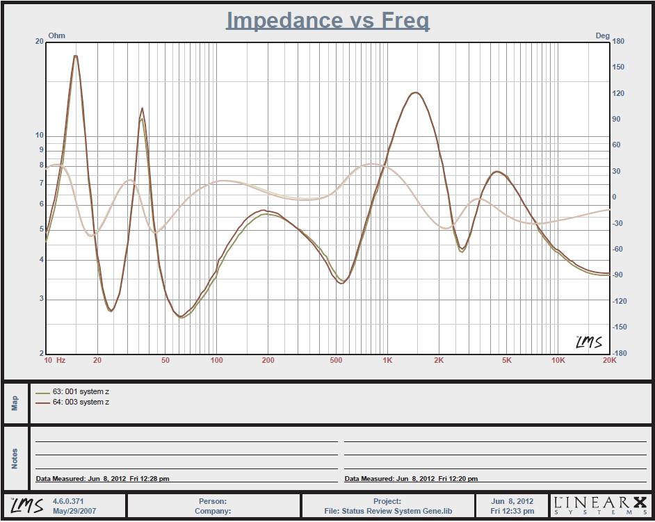
Impedance curve of the Status Acoustics Titus 8T. Impedance Caries between ~2.7 ohms and ~18 ohms.
The Mysterious Phase Angle
The phase angle, which also varies by frequency, is probably one of the less well understood aspects of a speaker’s electrical profile. The phase angle determines how much the current will lead or lag the voltage waveform in a reactive circuit. In an inductive circuit, the current will lag behind the voltage, and you’ll get a positive phase angle. In a capacitive circuit, the current will lead the voltage, leading to a negative phase angle. The phase angle will resultantly determine how much apparent power the speaker will see.
In spite of the phase angle’s role in equation (2), from the amplifier’s perspective we are not concerned with apparent power at the speaker. In one sense, you can consider the effects of phase angle being built into the frequency response (which represents voltage sensitivity over the full bandwidth): whether the phase angle is 0 degrees or 60 degrees, the voltage demanded from the amplifier remains the same. As a result you don’t have to worry that an amplifier is going to have to swing loads of extra voltage and current in order to cover the effects of a difficult phase angle.
From the amplifier’s standpoint there are two things we’re concerned with. The first is heat/power dissipation at the amplifier. In this respect, 45 is a magic number; at 45 degrees of phase shift, an amplifier’s output transistors will have to dissipate double the heat than if the load were purely resistive (i.e. 0 degrees of phase shift). Fortunately, 45 degrees is the worst case scenario for a real world loudspeaker; both above and below this point, the amount of power an amplifier is required to dissipate falls off.
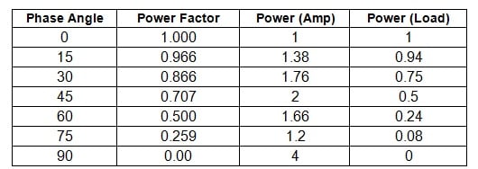
Power Factor, Normalized Amplifier/Load Dissipation Vs. Phase; Courtesy of Sound.Westhost.com
In the table above, Power Factor refers to COS(Ф) from our equations (2) through (4); Power (Amp) denotes the amount of power the amplifier must dissipate, while Power (Load) refers to the power through the loudspeaker.
The second effect of electrical phase from the amplifier’s standpoint could be qualified as an apparent cut in the load impedance. Remember, the voltage waveform is no longer in phase with the current, so peak current is no longer being sourced from an amplifier at the same time as peak voltage. At the extreme of 90 degrees (which would never happen with a real world loudspeaker), peak current is being sourced when voltage is 0, which isn’t too far off from the conditions of a short circuit.
So now that we understand just how hard a phase angle like +/- 45 degrees can be on an amplifier, what can we take away? First, it is important to understand that your average bench test into an 8 ohm resistive load (and even a 4 ohm resistive load) isn’t capable of telling you the whole story on how an amplifier will perform into a real world load. To handle a real world loudspeaker, a good quality amplifier must be built with the challenges of a less than benign phase angle in mind. Naturally, that takes a lot of heat sinking or active cooling and a robust output stage.
Conclusion
It is my hope that after reading and properly digesting this article, you the reader have a better understanding of the electrical characteristics of a loudspeaker, and how they matter when selecting an amplifier. Things are far more complicated than saying “Speaker X is 100dB sensitive, so you could power it with a potato!” Voltage sensitivity, impedance, and electrical phase all intertwine to determine just what you need in terms of amplification, and understanding how they interact is vital to making an informed decision. Use this knowledge well, and you’ll not need to spend thousands of dollars on an amplifier to drive reasonably sensitive speakers with relatively benign electrical phase and impedance, or conversely skimp on the amplifier when your speakers demand much more. Happy listening!
Acknowledgements
- Rod Elliot, Elliot Sound Productions
- Sergiu Ignat, Electronics Designer of Classe Audio
- Hadi Ebrahimi-Darkhaneh - PHD Grad Student, USF Electrical Engineering
Steve Munz is a “different” addition to Audioholics’ stable of contributors in that he is neither an engineer like Gene, nor has he worked in the industry like Cliff. In fact, Steve’s day job is network administration and accounting.
View full profile