
Lowering Mechanical Noise Floor in Speakers Pt 2
In Part 1 of this series devoted to loudspeaker panel vibration we took a look at the maths & theory underpinning the mechanics of panel vibration. Here in Part II, we'll take an empirical look at panel vibration, investigating with both accelerometer & microphone. The mechanical & acoustical performance of a loudspeaker cabinet's panel will be assessed at various stages of construction, with an eye to noting any improvements along the way. This report will conclude with a simple before/after comparison of the acoustical output of one of the test cabinet's panels, followed by a subjective assessment of the system's performance.
Damping
There are two modes of mechanical damping commonly employed in loudspeaker construction: extensional and shearing.

Figure 1: Free Later Damping Figure 2: Constrained Layers Damping (Extensional Mode) (Shearing Mode)
Extensional mode (free substrate layer) is an approach whereby a second, viscoelastic material absorbs kinetic (vibrational) energy from, in this case, a vibrating plywood panel substrate, converting it into heat (Fig 1).
The effectiveness of this approach depends upon the degree of panel flexure as well as the mechanical and physical properties of both the damping and substrate layers. Additionally, it's useful to know the mechanical properties of the adhesive used: if the mechanical impedance of the adhesive is low enough, the damping pad will function as a constraining layer. Whether this is actually desirable or not can only be determined by further measurement.
Shearing mode (constrained layer damping) as seen in Fig.2 , is an alternate approach whereby a vibrating panel is constrained by a second panel of sufficiently high mechanical impedance. In this mode, the two panels, one vibrating, the other constraining, are joined by an adhesive viscoelastic damping layer. Energy is dissipated through tensional forces of sheer deformation. Intuitively, it might appear the thicker the adhesive damping layer, the more damping. In practice, however, the opposite holds true: the thinner the layer, the more effective constrained layer damping (CLD).
So which method is best? In my experience (and all else being equal) CLD has generally provided for a higher degree of panel damping when compared to extensional mode damping, as applied to plywood cabinets constructed for mid-bass or even LF purposes. However, CLD is more costly and less forgiving where it comes to the selection of the appropriate materials. If the budget allows for it, experimenting with both approaches is recommended. If the budget doesn't allow for any experimentation, you'll likely find the less expensive, non-CLD approach works well, as you'll see in the following graphs.
In order to investigate the vibration-damping effectiveness of various materials, a test rig was built that allowed for quick, repeatable measurements of various, commonly available plywood panel samples along with various common, commercially available materials suitable for damping test sample vibration.
Figure 3 (Courtesy BBC)
Similar in appearance to that showing on Figure 3, the rig comprised two solid, heavy mount points to which the rectangular-shaped panel samples were clamped at each end.
The panel samples were set in motion by the impact of a 100 gram disk-shaped weight, dropped from a height of 30cms. The test panels were angled 45 degrees along their long axis. In doing so, the disk, when dropped on its edge, would impact, then fly off the panel, coming to rest off the panel, thus not interfering with the post-impact vibrational behavior of the individual wood samples. Low tech, but very repeatable and capable of producing consistent results.
Working up a series of before/after comparisons, as seen in Figures 6 & 7, didn't require absolute measurement values, therefore using an uncalibrated accelerometer is a valid approach. I could have used a calibrated accelerometer but chose instead to take the opportunity to experiment with an inexpensive accelerometer I'd seen mentioned in both online forums and print media.
The Measurement Specialties ACH-01 accelerometer chosen worked quite well and the +/-3dB 2Hz - 20 kHz typical amplitude response, along with a +/- 150g dynamic range made it a very cost-effective, suitable choice. It's available through retailers such as Digikey and makes for a worthwhile addition to any DIY Audioholics toolkit.
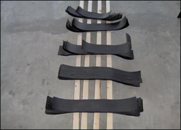
Figure 4 ; Figure 5
The wood chosen for this project from the half dozen test sample candidates was 19mm (.75") thick, void-free Baltic Birch. I use this (or its marine-grade derivative) quite a lot and have found it to be a consistently top-quality engineered wood product. (Figure 4.)
The damping material used in this case was a multi-ply "panel" built up from heavy, self-adhering roofing material. Sold in long rolls, the material is easily cut to fit as needed. Multiply the amount seen in Figure 5 by 5.5 to get an idea of the total amount used in the construction of both cabinets.
The half-dozen plywood test samples used were (free length) approximately 70 cm (27.6") long and just over 12 cm (4.7") wide. The free length was chosen as being a reasonable approximation of a typical loudspeaker cabinet's panel height. The width was chosen to keep mechanical impedance low and to minimize transverse resonance modes. The results of the test series was both encouraging and enlightening. The results showing in Figures 6 & 7 are taken from the Baltic Birch test sample.
Whether you use an inexpensive accelerometer, such as the ACH-01 or a more expensive calibrated accelerometer, a few caveats are in order. First, owing to the sensitivity of accelerometers suitable for measuring loudspeaker panel vibration, it's easy for extraneous vibrational noise from such things as nearby fans, motors, traffic, etc to creep in to your measurements. Second, be consistent in your use of whatever base or support your cabinet under test is situated upon. Measure your cabinet while it rests on, for example, the concrete floor of a garage, then re-measure it, this time with the cabinet perched on top of a wooden workbench and you'll be looking at very different results, invalidating even comparisons based on relative amplitude measurements.
On the left hand side of Figure 6, we see the amplitude response generated by the accelerometer fixed to the undamped panel sample. On the right hand side we see the response of the same sample but with the damping material lightly affixed to the panel. (Both impulse responses are on the same amplitude/time scale). Already a significant difference is evident. Clearly, the plywood panel, when damped, settles much more quickly than when undamped.
Figure 6
The damped response showing in Figure 7 is that which resulted when the damping material was directly adhered to the plywood test sample.
Figure 7
In Figure 7, an improved settling time can be seen when comparing the damped amplitude response showing here with that seen in Figure 6. Clearly, adhering each layer to its neighbor, then adhering the multi-ply damping panel directly to the plywood test sample is an effective approach.
Its tempting to think that when it comes to the application of a damping material, the more the better. However, there exists a diminishing returns effect and inevitably there comes a point where more is not better. From an empirical standpoint, building a damping pad of the particular material used in this project ½ to ¾ the thickness of the plywood panel substrate is a good starting point when setting out to determine optimal thickness.
Testing the Cabinet, Measurements, Conclusions
Test Cabinet Construction
Having assessed the effectiveness of the free-layer damping approach when applied to test samples, it was time to build the test enclosures.
Each enclosure was designed to have 4 solid cross braces, oriented horizontally, fixed to the interior side of the cabinet's side & back panels, with the front edge, close to, but not touching the inside of the faceplate. An FEA simulation done prior to construction indicated 4 cross braces would produce acceptable results.
To gauge the effectiveness of the bracing & damping approaches chosen, a series of measurements were made at different points in the construction process using the ACH-01 accelerometer, along with a calibrated microphone for capturing acoustic measurements, useful in subsequent analysis.
![[Figure8]](../../../images/figure8.jpg)
Figure 8
The enclosure sported double-thickness (38mm) front, top & bottom panels, with the sides & back being single thickness (19mm) panels. Figure 8 shows one of the enclosures, midway through construction. In addition to the 4 horizontal, shelf-style braces, the front panel was cross-braced as well, with a thin shelf style 5th brace running from the inside center point of the faceplate to the back of the enclosure. The use of extensive bracing and damping added to the already substantial weight of the cabinets. The completed enclosures weighed in at over 100 kg (220 lbs) each!
In Figure 9 can be seen an heroically busy collection of plots, each sweep indicating the vibrational behavior of the panel to which the accelerometer had been affixed (the center of the left or top panel in Figure 8) at various stages of construction. The net before/after result of all of the bracing, damping & stuffing can be seen in Figure 10.
Figure 9
In Figure 10, a general downward shift in amplitude, accompanied by an upward shift in frequency is noted when comparing the "after" curve with the "before" curve. Keep in mind these are not dB SPL curves, but the relative response of an accelerometer responding to the cabinet panel's acceleration at each frequency along the sweep.
Figure 10
Figure 11 is the "before" and "after" vibrational response to impulse stimulation. (In this particular graph, "before" is the response plotted on the right, the "after" plotted on the left). The improvement in settling time is striking.
Figure 11
Thus far, we've seen what the accelerometer has had to say. To see what the microphone had to say, I employed the noble and familiar knuckle-rap test. I removed the accelerometer, rapped away at the spot formerly occupied by it, with the microphone positioned nearby. In Figure 12, the purple "before" curve presents a generally higher relative amplitude response than the green "after" curve. The difference, however, sounded much greater than it appears in this graph.
Figure 12 Spectral Analysis, Before/After Knuckle-rap test, Cabinet 2
Note: Figures 13 & 14 are the time-domain versions of the data presented in Figure 12.
Figure 13 "Before" Knuckle-rap test, Cabinet 2
Figure 14 "After" Knuckle-rap test, Cabinet 2
Subjective Assessment & Closing Comments
Measurement indicated that the various measures taken to reduce panel vibration were indeed effective in lowering the mechanical noise floor of the system. However, objective assessment tells only part of the story and a subjective assessment is required to complete a picture of any system's performance.
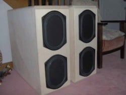 In Figs. 15 (right) we see the test system, at an earlier stage of construction, awaiting completion of the other modules making up the architecture of the full system.
Though the cabinets are attractive in their unfinished state, with an appearance reminiscent of, for example, some of Axiom's current line of products, they will eventually have a finish applied. The choice of finish, though, is left to my wife - an effective approach for increasing WAF or SAF. Now there's a tip for DIY Audioholics everywhere!
Two listening tests were conducted. Each lasted about an hour. A variety of material with which I and the 4 other listeners who had taken the time to audition the system with me were very familiar with was used. The upstream test gear used in both instances was the same (Hafler DH-500 power amp, etc).
At the conclusion of both tests, results were tabulated. From the raw data collected, I threw out everything people thought they heard. Owing to the very informal, very unscientific nature of the test trials, I was interested in certainties only. I also threw out those items for which no consensus could be reached. In the end a few things did emerge.
First, resolution of low-level detail was dramatically improved. This was not some at-the-fringe, barely discernable effect; it was a substantial improvement. On this point, all listeners were unanimous. I heard things in recordings I have listened to for decades that I had not heard before.
Second, overall mid-bass clarity improved, resulting in, among other things, improved sound staging. Individual instruments, such as cellos in classical recordings were now discernible as individual instruments, where before they tended to sound more like massed string choruses, made up of not clearly identifiable individuals. The tonal differences between different pianos, such as Steinway, Yamaha, Blüthner, etc was now clearly discernible
It appeared that the "before" mechanical noise floor had, in addition to obscuring the low-level mid-bass detail beneath the murk of mechanical noise, imparted a euphonic "sameness" to everything played through the system. Now that "sameness" had been largely, though not entirely, eliminated. Overall, the system's presentation had become more realistic & musical and that resulted in a more satisfying listening experience. Not bad when considering how old a technology the KEF B139 drivers used represent.
About the drivers …
I first became acquainted with the KEF B139 drivers back in the late 1970's. In those days I was working in a recording studio "programming" a Moog synthesizer. ("Programming" back then meant plugging the Moog's patch panels full of patch cords). I remember carrying around a 3-ring binder full of preferred patches. Ancient history!The synthesizer fed its output, via a Dynaco power amp, into a Pair of IMF transmission line loudspeakers that used the B-139 as the woofer. The bass those things could crank! My teenage ears were impressed.
Outside of live music situations, I had (up to that point) never heard such low bass at such volumes. (Remember, we're talking late 70s here - monster subs were not as commonly available as they are today). Years later I would see B139's used in Wilson Audio's $100k + US WAMM loudspeaker system.
Over the years I acquired half a dozen of the units for my driver collection, used mainly for research purposes. As lately they had just been lying around gathering dust, when it came time to build a general-use system for the house, it was an easy choice to design the mid-bass modules for the system around them.
Though technology has certainly provided for many substantial advances in driver quality since the B139s were first introduced over 30 years ago, there are some things they do well, to this day.
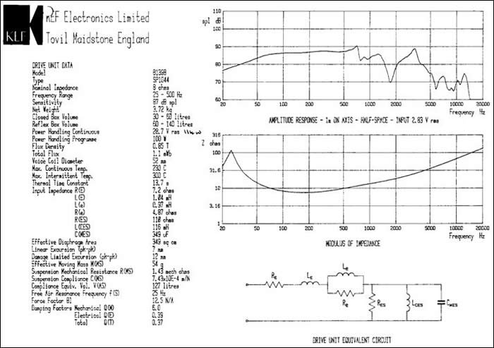
Figure 1 7 B139 Spec sheet, ca. 1980's
Resources
1. Beranek, Leo L., ed.: " Noise and Vibration Control ", McGraw-Hill, Inc, New York , © 1971
2. McIntire, M. E., et. al.: " The Influence of Geometry on Linear Damping ", Acustica, Vol. 30, #4, 1978
3. Caldersmith, Graham: " Vibration Theory and Wood Properties ", Journal of the Catgut Acoustical Society, #42, November, 1984
4. No Author listed " Measuring Vibration ", Brüel & Kjær, Nærum , Denmark , September, 1982
5. Eren, Halit, " Acceleration, Vibration & Shock Measurement " The Measurement Instrumentation and Sensors Handbook, CRC Press, © 1999
6. Brown, Alastair, W. M.: " The Ensemble Statistics of the Response of Structural Components with Uncertain Properties ", Doctoral Dissertation, University of Cambridge , March 2003
7. No Author listed " Piezo Film Sensors Technical Manual, Part 11 of 18 ", Measurement Specialties Valley Forge , PA , © 1998
8 . Renninger, Jennifer : "Understanding Damping Techniques for Noise and Vibration Control ", E-A-R Specialty Composites, Indianapolis , Indiana , © 2000
9. Green, David W., et. al.: " Mechanical Properties of Wood ", Ch. 4, Forest Products Laboratory Wood Handbook, Madison , WI , © 1999
10. Harwood, H. D., et. al.: " Factors in the design of loudspeaker cabinets ", BBC RD 1977/3, © January 1977
11. Iverson, J. K.: "The Theory of Loudspeaker cabinet Resonances", Journal of the Audio Engineering Society, Vol. 21, #3, April 1973
12. 11. Tappen, P. W.: "Loudspeaker Enclosure Walls", Journal of the Audio Engineering Society, Vol. 10, #3, July 1962
13. Caldersmith, G. W.: " Vibrations of Orthotropic Rectangular Plates ", Acustica, Vol. 56, © 1984
14. McIntire, M. E., et. al.: " On Measuring Wood Properties, Part I ", Journal of the Catgut Acoustical Society, #42, November, 1984