
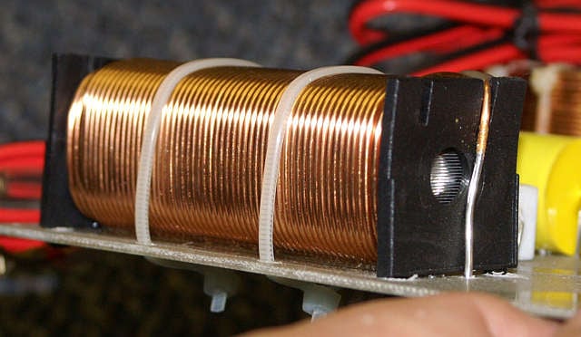
The Loudspeaker Crossover Part II: The Brains of your System
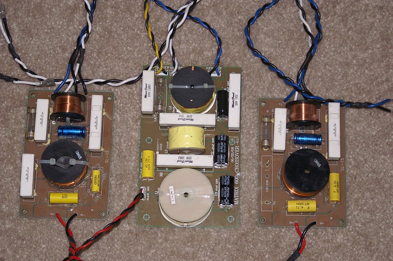
Madisound Kit
Do Better Quality Parts Really Matter?
In part one of "Crossover, Brain of your speaker system", we introduced the concepts of inductance, capacitance, and resistance. We then examined how these three basic passive elements relate and combine to create frequency selective networks called High pass and Low pass sections, the building blocks of the crossover network. We also considered in part one, the effect of real loudspeaker impedance, and how, unlike a resistor, its amplitude and phase vary with frequency to complicate and frustrate the function of constant resistance type crossover networks. These real loudspeaker impedance variations result in frequency and phase responses which end up being very different than what our textbook equations would have us expect, because they assume a speaker behaves like a simple resistor. We also made the assumption that the parts used in our crossover networks were theoretically perfect and without flaws. In part two, we will discuss how in the real world, capacitors, inductors and resistors exhibit behavior which is neither ideal nor perfect. We will determine if better quality parts truly yields better performance.
Some of my more recent efforts
Real world parts, the kind you will actually find in your own crossovers, suffer from many flaws. In part two, we will discuss and illustrate the effects of some of these. We will also examine how simple mistakes, like the physical orientation and location of inductors on the crossover board can result in non-ideal behavior like cross-talk. This article will allow the reader to gain some insight into the kinds of mistakes made by amateur and professional crossover designers alike, and allow us to recognize compromises in crossovers by simply looking at the networks. We also hope to gain some understanding into flaws which are not quite so easy to see with the naked eye. While this article is not going to be an exhaustive study of crossover component parts, it will touch on most of the major flaws present in the three basic components used in all real world crossovers, resistors, capacitors, and inductors.
I am hopeful this light shed on crossover networks will make you all better and somewhat more cynical consumers, ones who understand the importance of the passive crossover parts used in their speaker system. Reading some of the more ardent audiophile press, one can be left with the opinion that there is all sort of magic going on in this network. In fact the enemies of these passive components are basically the same as the enemies of all electronic parts; hysteresis, loss, tolerance, insufficient power handling capacity, insufficient space, and compromises made on behalf of cost.
Resistors & Tolerances
Let’s start by considering the simplest of the three electrical components used in our crossover, the resistor. It will, in combination with inductors and capacitors create time constants used in frequency selective circuits, although by itself the resistor does nothing other than to consume power. In a crossover network, resistors are usually used in combination with other components to control either impedance magnitudes or the relative levels between different drivers in a system. Resistors are most often used in "padding" a tweeter which is more efficient than the woofer, so the overall system frequency response will be flat. The resistor, in series or parallel with capacitors and/or inductors, is often used as part of a Zobel or impedance compensation network.
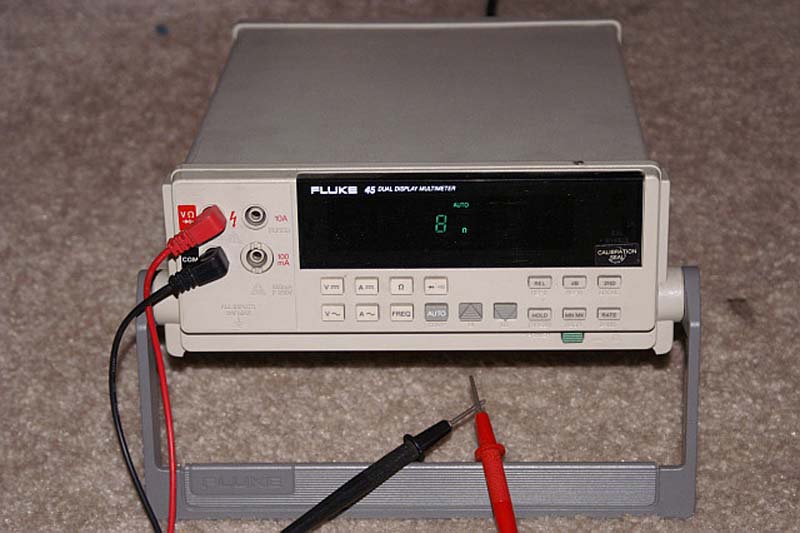
A good Meter is the best way to "Trust, but verify"
Of all flaws with which we must deal, the simplest to understand is tolerance; the allowable variation of the components value, whether that component is a resistor, inductor, or capacitor. No surprises here, everyone can understand how a part with a small 1% tolerance will lead to a more uniform and reliable frequency or amplitude response performance than a part with a 10% tolerance. The tolerance issue, while seeming obvious, becomes more critical as we increase the order of the network. Remember, a first order network has one part with tolerance, while a third order network is going to have 3 which vary with tolerance. It is for this reason that the higher order the network, the greater the need for a tight component tolerance. Said another way, for a given amount of allowable variation in response, (plus or minus 1 db for example), a second order network requires tighter tolerances from its components than does a first order network, and a third order network requires tighter tolerances than a second order network. As we increase the complexity (order)of the network, the sensitivity of the network to component tolerance increases. So, as we increase the network order, not only do we add additional parts, for a given crossover frequency, we require both larger size (value) components and tighter tolerance in those components in order to keep the frequency response window tolerance the same as the simpler network. This is often a hidden and un-calculated cost in using higher order networks. This exponential rise in part size and cost should explain why crossover networks are almost never found in complexity above fourth order.
Resistors normally deviate from their design values within a window of anywhere from 0.1% to 1%. If you buy a 5% 10 ohm resistor from an electronic store, you might go back there complaining you measured it with your meter and found is was only 9.5 ohms, but if you get a refund it is because they are hoping you don't return to buy more stuff. You will find neither the highest or lowest tolerance parts in most crossover networks, as the typical tolerance specification is either 10% or 5 %. The letters (K) and (J) on the part will indicate if it is 10% or 5% respectively. The effect of this variation is one of magnitude and is important to hold close enough so that there is not much variation from one speaker system to the next. Lets consider an example.
We have an 8 ohm tweeter which is 6 db hotter than the woofer in the system. If we put an 8 ohm resistor in series with the tweeter, the combination of the 8 ohm series resistor and the 8 ohm tweeter presents 16 ohms as a load to the amplifier. Since power = V2 /R and since we have doubled R, we have halved the power the entire network (resistor plus speaker) consumes from the amplifier. The amp is delivering 1/2 the current to the loudspeaker load. Now half of the power that is delivered is consumed in the series resistor, the 8 ohm resistor in series with the tweeter. So, we have cut the power in half twice, and therefore get (- 3 db) + (- 3 db) = ( 6 db) attenuation. Let's say we pick a 10% tolerance for our resistor. This generally defines a 20% allowed variance, since the specification is +/- 10%. We are making a stereo pair, and the two resistors we use are 8.8 ohms, and 7.2 ohms respectively, both within our 10% tolerance window. In the first case, (8.8 ohms in series) we attenuate 6.44 db, and in the second case (7.2 ohms) we attenuate the signal 5.57 db. This means we have a mismatch between our pair of 0.87 db, and a definitely audible difference. This same magnitude variation (tolerance) when the part is used in conjunction with a capacitance or inductance will also cause a shift in the frequency corner of the network.
Another very well documented issue with resistors is inductance. While high impedance, small wattage resistors are most often made from a metal film, higher wattage parts of low impedances (the kind most likely to be used in crossover networks) are often wire-wound parts. (If you have never noticed before, the symbol for the resistor is a bunch of wire scrunched up). Some old wire-wound types have a inductance high enough to cause issues in a crossover at very high frequencies. You may often find wire-wound resistors being referred to as "non inductive" to let the buyer or engineer know these parts have eliminated this potential flaw. Modern day parts are often wound with a serpentine pattern so the windings have self canceling inductance without having an effect on their intrinsic resistance.
The largest real world problem you will run into with resistors, is a universal problem for all components, heat sensitivity. As we read the specifications for any component, we must bear in mind that these specifications are only met within a certain allowable window of temperature.
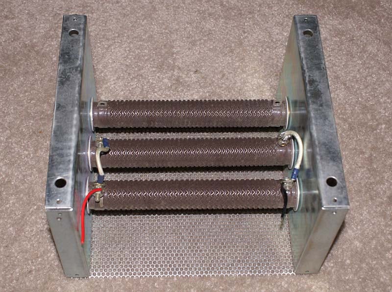
An American Made Resistor Bank - 3 times 300 Watts
Temperature dependence of resistance
The electrical resistance of a metal is approximately proportional to its temperature over a limited range. Resistivity of materials is usually specified at normal room temperature, 20 degrees C (68 degrees F). If one knows the resistivity of the material at room temperature, and the rate at which it changes, we can calculate the resistivity at other temperatures with the following formula:
![]()
Where:
R = Resistance at temperature T
Ro = Resistance at temperature To
To = Temperature at Reference T (usually 20 degrees C)
alpha (the Greek letter with the bracket and outside parenthesis) = Percentage change in Resistivity per unit temperature
Let’s work one example. Suppose we put an 8 ohm resistor into a crossover network, and use it to drop
the sensitivity of the tweeter so it will match the woofer. Lets say we are driving the speaker system pretty hard, and we are heating the resistors so that they rise to be 200 degrees F, (a not uncommon operating temperature for a resistor in a crossover network). 200 degrees F is equal to 93.33 degrees Celsius. (Celsius and Centigrade are the same). If the resistor is wound from Copper wire, the temperature coefficient would be (3.9 * 10-3)) / deg C. Since the resistor was 8 ohms at 20 degrees C, and has now heated up to 93 degrees C, the new value of resistance would be:
8 * [(3.9 * 10-3 / oC(93.33C - 20C) + 1] = 1.286 * 8 = 10.288 Ohms
We can plainly see this increase of 25% is more significant than the component tolerance of 10%. Suppose we do not use copper in the wire-wound resistor. If we use a material called Nichrome, which is basically an alloy of nickel and chromium, our change in resistance will be considerably less. Nichrome has a low resistance variation (alpha) with temperature, alpha = 0.4 e-3/ (deg C) Using this material to make the resistor gets us an eventual resistance of 8.23 ohms at the elevated temperature of 93 degrees C. This is an increase of only 3%. This is no doubt, a small increase compared to the change of resistance in the voice coil which is either copper, aluminum, or a combination of those two.
As the power dissipated in a resistor increases, so does its temperature. As the temperature increases, so does the parts resistance (as illustrated above). As the resistor is heated, its ability to absorb power is compromised, and its value in the circuit is not as designed. That resistors get hot, and can burn out is a well known phenomena. What is not as well known is that running high power into resistors at or near their limits brings with it audible effects on your music.
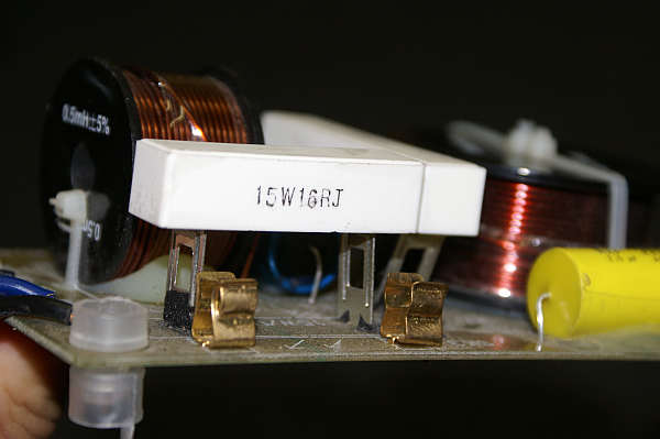
Since the resistor manufacturer has no control over how the part is mounted to the printed circuit board (PCB), or its orientation, proximity to other parts on the PCB, they cannot predict with accuracy at what point the power through the circuit will cause the resistor to go outside of its allowable range. Take a look at the resistor in the photographs below:
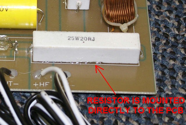
The 20 ohm resistor shown above (white rectangular part) is mounted directly to the printed circuit board (PCB) which is an effective insulator of heat. The path for the heat generated inside the resistor to escape has lost 1 of 4 large sides. Now lets take a look at another PCB which has eliminated this issue.
On this PCB we see the terminals of the resistor are designed to stand the part off the board. This has the disadvantage of making the part taller, but the advantage of creating space between the hot resistor (whose only job is to dissipate power) and the PCB (whose only job is to connect the different components without routing the heat from one part to another). With the resistor mounted off the PCB, the hot air can circulate around the part more easily, dissipating the resistors power more efficiently.
Suppose both of these parts shown above are 20 watt resistors. Which one burns out first? Now suppose one of the boards is mounted to the bottom of the cabinet so the heat from the resistor can rise into the entire cabinet volume, and escape through a nearby port. Suppose the other PCB is mounted upside down on the top of the cabinet, inside a sealed speaker box, and under the cabinet stuffing which is fiberglass? Although both parts are 20 watt resistors, the one in the heat containing environment is going to burn out faster than the one with good ventilation when it needs to handle all 20 watts. Power ratings on resistors are NOT independent of the way in which they are mounted to a PCB.
The Loudspeaker Crossover Part II: Capacitor & Inductor Issues
Capacitors imperfections
Now let's discuss the capacitor. (For those of you who want to read more detail on the performance issues with real world capacitors, there is an excellent treatment of the subject in Wikipedia @ http://en.wikipedia.org/wiki/Types_of_capacitor).
There are many non ideal behaviors that capacitors show, but perhaps the worst is dielectric absorption. This is a fancy name for capacitor memory. The dielectric is the material which insulates the two electrically conductive rolled plates in contact with the capacitor terminals. This dielectric material is how we specify the capacitor type, e.g., mylar, polypropylene, electrolytic, ceramic, etc. With Dielectric Absorption (DA) even after the initial voltage gets removed from the capacitor terminals by shorting out the capacitor, the capacitor returns to its prior state of charge without any signal being supplied. The energy which returns comes from the electrical insulating film, or dielectric, in which it was stored. Problem is, the dielectric is not supposed to store a charge. Use of polystyrene, polypropylene and Teflon as dielectrics will keep this effect to a minimum. This effect (DA) is also known as dielectric absorption hysteresis. Hysteresis is the storage of energy in a medium. It is what makes our permanent magnets work, causes speakers to drift off center position, and what make a magnetic cored inductor distort even without saturating.
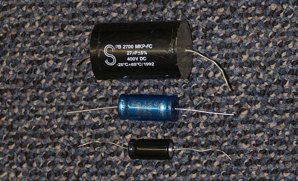
A 27 ufd polypropylene and two 22 ufd non polar electrolytic capacitors
In the photograph above are three capacitors. The two smallest are both 22 ufd, 5% tolerance and 100 Volts ratings. The blue one in the center is about twice as large (volume not length) as the small black one. You can see the relative size of the 27 ufd Solen 400 Volt Polypropylene capacitor at the top of the photo. Which one of these three do you think will handle the most power? Which will handle the least? If you want a good seat of the pants approach for determining capacitor quality, here is a clue. For a given capacitance, bigger is almost always better.
The Q or quality factor (Also known as Dissipation Factor or DF) of a capacitor is a measure of its losses of signal due to leakage and Equivalent Series Resistance (ESR for short). The HIGHER the Q of the capacitor, the less losses it will impose on the signal. Secondary to the signal loss, is that high DF capacitors will create more heat while they are passing the electrical signal. An ideal capacitor will not dissipate or absorb any electrical energy. A real capacitor will, and the resulting heat it generates, will likely mean the capacitors ESR will increase, meaning it will be easier to generate more heat and more loss. This is a little bit like the situation with a transistor getting hot, and increasing its native gain, which makes it get even hotter. With transistors this is known as thermal runaway. In short, the effect from the heat exacerbates itself, like positive feedback in a microphone feeding a loudspeaker.
Some of us will always prefer to "Roll our Own"
In a loudspeaker, the heat which increases the voice coil resistance means that the voice coil draws less power from the voltage amp as the voice coil gets hotter. (Heat in this instance acts like a compressor). With a capacitor getting hot, it starts to dissipate even more power, not less. While heat tends to make the voice coil self limiting, it makes semiconductors and capacitors likely to run away with an accelerating problem. While this effect (DF) is measurable in film dielectric capacitors, like mylar and polypropylene, it is not likely to be large enough to be audible. Dissipation Factor (DF) IS a serious issue with electrolytic capacitors. My very first consulting job in 1983 was fixing a crossover for a DJ in New Hampshire. When I opened up his speaker, I found his electrolytic capacitors had gotten SO HOT they literally blew up. All that was left of the electrolytic capacitors used was the plastic covering over the metal capacitor cases. The parts failed and exploded! (In the DJ business, it is often about how loud you are more than how good you sound).
When you are comparing electrolytic capacitors, and you notice some of these parts are much smaller than others which seem to bear the same specifications, it means you have left out one very important specification, that of DF (Dissipation Factor). This is often a good measure of the life of the part, along with its Voltage and temperature rating. This imperfection is THE compromise made with capacitors in order to keep both the size and the cost low. The initial cost that is. If it blows up in your crossover, it may not have been worth saving the initial $2 you saved at retail. Since this is something hidden inside the speaker box, the manufacturer often believes the buyer ignorant of this, so they elect to pocket the savings, hoping the cheap parts used will outlive the life of the warranty.
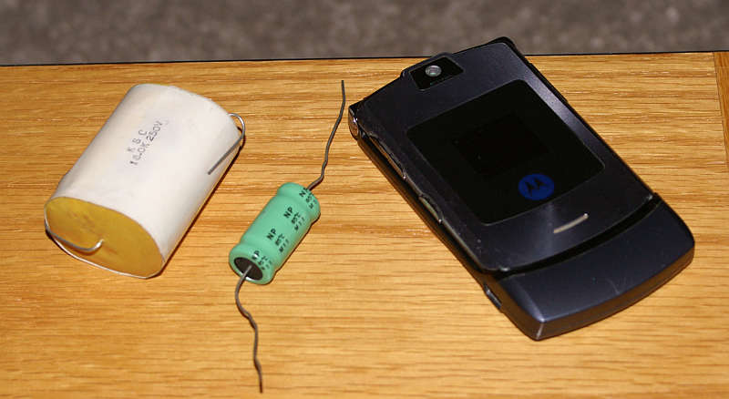
For a sense of scale, a flip phone, 18 ufd electrolytic (green) and 18 ufd Mylar (white)
Like the resistor, the capacitor can also be inductive at a high enough frequency. This ill effect is known as ESL (Equivalent Series Inductance). (We use the letter L to designate an inductor in a circuit diagram). In case you have wondered why Choke, Inductor and Coil is represented in electronic circuits by the letter "L" it is not solely because "C" was already taken by the capacitor.
For some background on this go to: http://en.wikipedia.org/wiki/Lenz's_law
In the world of the crossover, ESL is not likely an audible phenomenon, given the high inherent inductance of most loudspeakers. Audiophiles will likely want to argue with me on this point, so let me deflect this by saying when I discuss audibility I do not include the most sensitive audiophiles in the discussion. Some audiophiles claim hearing abilities rivaling that of bats and sonar equipment. That said, if measured you will find the typical tweeter has 100 times or more inductance than the most inductive capacitor likely to be in series with it. If one is using a very large capacitor, such as a 200 ufd electrolytic, then it may be helpful to bypass it (parallel) with a 0.1 - 0.5 ufd film capacitor to effectively eliminate the ESL. Unlike DF or DA, ESL can be eliminated by a lower value capacitor being used in parallel.
Inductors - The Most expensive & Most problematic Crossover Element
Let's consider the subject of chokes. Once again I am inclined to thank collectively the authors of Wikipedia for an excellent treatment of Inductance, and its close relatives, EMF, magnetic flux, and magnetism. There is enough physical science behind an inductor to write not just one article but several large textbooks, and many scientific journal articles.
For an excellent general treatment and links enough to keep the scientifically curious busy for days: http://en.wikipedia.org/wiki/Inductor This page shows no less than (6) different formula for calculating inductance of an air core choke. (So try not to go nuts....)
The primary figure of merit for a crossover coil is its Quality factor (or Q) for short. The quality factor of a coil is determined by:

Where
W(Omega) = 2pi*Frequency
L = Inductance in Henries
R = Resistance in Ohms
Ignoring all else but the resistance of the choke we can see as this figure goes to zero, the Quality factor (Q) approaches infinity. We can also see from this, that a choke of 1 millihenry inductance having a resistance of 0.5 ohms, has the same quality factor of a choke of 2 millihenries inductance having a resistance of 1.0 ohms. This should make it obvious to those who understand that as the crossover frequency goes lower, the size of, cost of, and importance of the quality factor (Q) of the inductor becomes more and more important. Two ohms in series with a four ohm woofer, is still a bigger problem than one ohms will be with regard to losses. This is one important reason why manufacturers sometimes shy away from systems having very low crossover points. Even when it is better for performance, it is often so costly to do it right, that a higher crossover point gets chosen for budgetary reasons.
2.0 mH air core Jantzen from Parts Express = $11.00 each = 0.80 ohms DCR
2.0 mH iron core Erse from Parts Express = $ 7.49 each = 0.26 ohms DCR
On the face of it, the magnetic core choke seems to be a better deal.
A laminated Steel Core Choke
Inductors are the biggest attention getters in the passive crossover and for good reason. They are usually the largest and most expensive parts used, and they are present in sizes and masses that have few real analogs in the electronic world except for transformers in power supplies or charging coils used in magnet chargers. Inductors are subject to losses much more so than capacitors. While one can buy a high quality mylar or polypropylene capacitor today for a few dollars, a very high quality large value air core choke is still many times more expensive than that high quality capacitor.
Like electronic components on a PCB, sometimes the inductors are not just inductors, sometimes they are transformers as well. (Just like sometimes loudspeaker voice coils are inductors when they were trying to be simple resistors). For those of you familiar with the construction of transformers, you will remember they are two separate electrical windings both put on a common magnetic core which is intended to link them together by electromagnetic field coupling, also sometimes called inductive coupling.
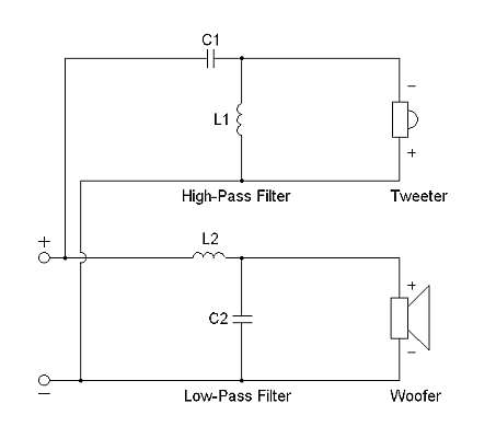
Let’s take a look at the following circuit:
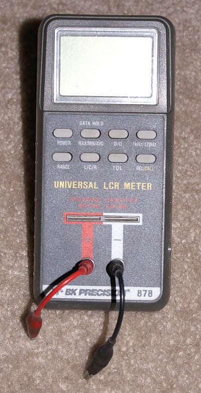
An inexpensive LCR meter will Define the deficiencies of your parts
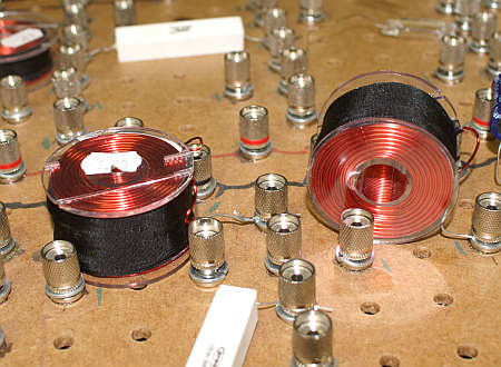
Let’s say we used two chokes, both 3 mH and both randomly placed on the PCB. Here in my lab on the prototyping board, they look like this:
If we curve the HP and LP function of this network, we find the following frequency responses:
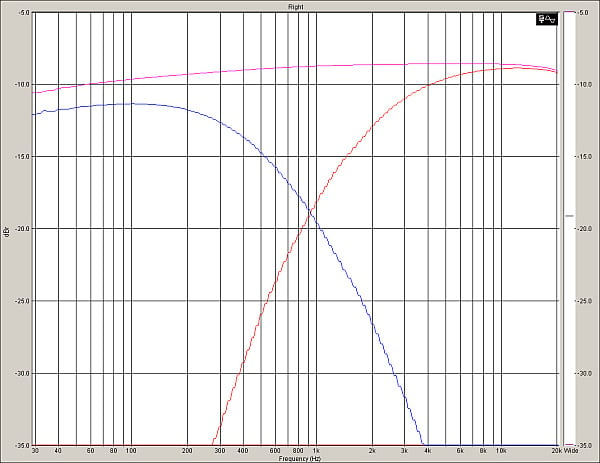
Frequency Response of System with Separated Chokes
We have our expected High Pass and Low Pass function, but we might notice there is more loss in the LP than the HP filter. Of course, we say, the inductor is in series with the resistor load in the LP but in parallel on the HP circuit. That results in a significant series resistance being placed between the amplifier and the load, in this case a 5.6 ohm resistor. Now, lets’ move the inductors so that they are physically on top of one another, (see photo below) stacked so they share the same diameter and run the test again.
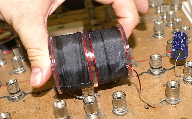
HP and LP Chokes Stacked so they inductively couple
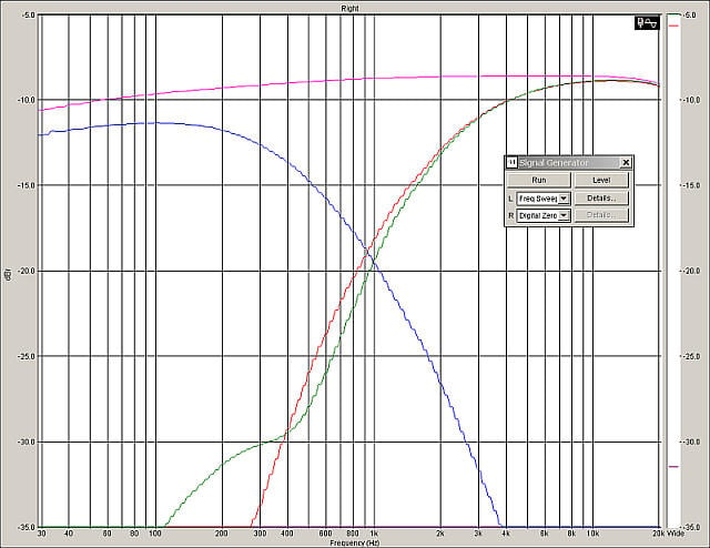
Change in HP response due to stacking the HP and LP chokes
Looking at the green and red HP curves, we might notice two things here. First, we have an increasingly divergent stop-band on the HP filter section, and second, we have less rejection (below 400 Hz). Why? Because the close proximity of the two inductors means they are inductively coupled so we are getting crosstalk. Because the signal is coupled between the two inductors, the series LP choke, and the parallel HP choke, we get a lessening of the out of band signal rejection of the HP section. Two conductors are inductively coupled when they are configured such that change in current through one wire induces a voltage across the other wire. By placing one inductor on top of the other, I am inducing currents to flow in the HP choke because of the current flowing through the LP choke. It is for this reason that you will often find crossover chokes places at right angles to one another as pictured below when laid out on a PCB. This orientation eliminates most of the inductive coupling that would occur inadvertently.
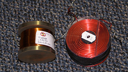
A 5.6 mH magnetic core and a 3.6 mH air-core choke side by side
In the photo above we have two different kinds of Inductors. Magnetic and Air core. The magnetic core (left) is 5.6 mH and has a DCR of 0.28 ohms. It is wound from 15 AWG copper wire. The 3.0 mH air core choke, wound from 16 AWG copper wire has a DCR of 0.75 ohms, or three times the resistance and about 64% of the inductance. This means the loss in the Air core is about 4.66 times as great as the iron core choke. In order to both minimize the inductors resistance and cost, vendors have wind chokes on magnetic cores. There are different types of magnetic core materials used, depending on the frequency range the choke is to be used in. The beauty of using a magnetic core, is the huge savings in copper wire for a given inductance. (If I say laminated steel or ferrite or powdered iron, someone will feel compelled to explain to me the difference, and why one is superior to the other, so I shall simply differentiate inductors by saying magnetic or air core.) Because the magnetic core increases the permeability of the inductor, confining the magnetic field more closely and with greater intensity; you reach a given inductance with fewer turns of wire, allowing you to make a part which, for a given size, is going to have a much lower DCR than its air core counterpart. This means you will lose less power in your series LP chokes. It is this reason (plus cost) that we use magnetic cores in inductors.
On the face of it, the magnetic core choke seems to be a better deal all the way around. So, why then with all these advantages would anybody use anything but Magnetic core chokes? There are two reasons. Saturation, (an effect of running out of permeability by the ferrous core) and hysteresis, the storage of energy, which is present with all magnetic materials. Which problem is worse for the crossover designer; loss of signal due to higher resistance, or the nonlinearity of the magnetic core choke? This depends in large part upon the magnitude of the difference. This is why small value chokes are almost always air core, while very large value chokes are almost always magnetic core. I dislike taking sides in such debates when both approaches have distinct advantages. Personally, I can easily hear the distortion made by iron and steel core chokes, and would rather live with the higher cost and higher (but relatively constant) resistive losses in the air core choke than hear the distortion in a magnetic core choke. Unfortunately, at very high inductance values, air core chokes quickly become impractical because of their weight, size and cost.
Let's take a look at the following circuit, a simple first order low pass filter attached to some lab gear.
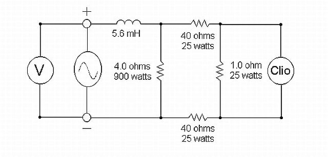
The Sine wave symbol indicates the power amp, in this case a bridged "3000 watt" power amplifier, and the V is the voltmeter, a Fluke model 45. The 5.6 mH choke is shown here as air core, but both air and magnetic core chokes were used for this experiment. Clio is a popular hardware/software system designed specifically for measuring audio. The input to the Clio box is put across a small 1 ohm resistor, placed between a pair of 40 ohm resistors so as not to load the bridged power amp, or cause an input voltage overload to the very expensive Clio box, which might cause the Clio to smoke, and me to lose my day job.
The point of this circuit is to see if I could measure distortion in the resistor load, and identify that distortion as originating from the changing impedance of the magnetic core choke. The theory is, if the core permeance is changing as it nears saturation, then the impedance of the choke will also change. Since an AC waveform varies its magnitude with time, the amount of saturation that occurs will be greater at the peak than elsewhere in the waveform. If that is true, this will generate a distortion in the voltage waveform and therefore in the resistor load, as the current flowing will not be faithful to the original input voltage. As the AC waveform varies, the current should follow it. Since the AC waveform varies its amplitude with time, even with a relatively invariant AC signal like a pure tone, how bad would it be if the signal had a crest factor of 20 db, not uncommon in music, instead of the relatively modest 3 db crest factor of a pure tone? Through the entirety of the AC waveform, the current will only be proportional to the voltage if the impedance does not vary (and like 99% of all amps, the power amplifier is a voltage amp, not a current amplifier).
The Loudspeaker Crossover Part II: Measurements & Conclusions
The screen-shot below, shows the Clio input shorted to its output so we have a reference of the signal used for the magnetic vs air core choke test.
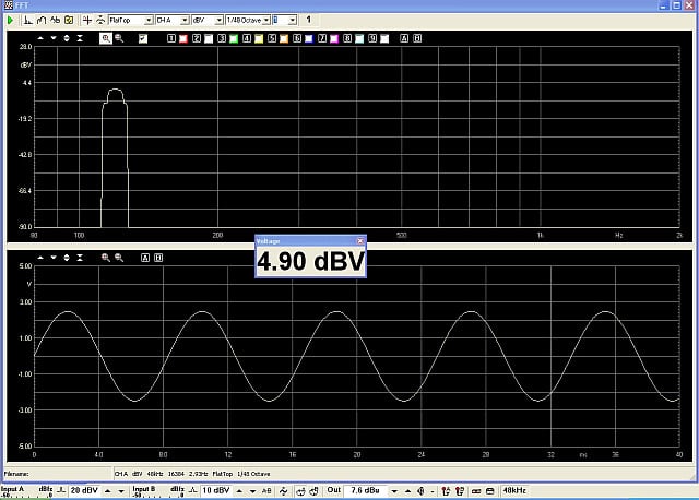
The noise floor of the Clio is below the -90db level at the bottom of the top screen
The screen-shot above is a dual view, with the top screen a spectrum analysis, amplitude vs frequency; and the bottom screen an oscillogram, or the voltage vs time view. Both views are two ways of examining the exact same data. If our choke and amplifier are perfect, the measurements will look exactly like the view above. Since our 4 ohm resistor is able to dissipate 900 watts RMS, and the bridged amplifier is rated to deliver 3000 watts into this 4 ohm load, we will limit the power into the load bank to 900 watts. To further limit the resistor heating, we will use a sine wave which is on for one second and off for two. With this arrangement we can take a stable measurement while reducing the long term (3-second avg.) power to only 1/3rd of the signal-on condition.
Now if my theory is correct, we do not go from "the choke is perfect", to "the choke is saturated" like a light gets switched on or off. If the magnetic core saturates, this effect should happen gradually as the alignable magnetic domains available become more rare, as the magnetic material runs out of them (this is saturation). We should be able to see this effect by viewing either the time or spectral data. When we examine the sine wave above, it reminds us that the AC signals are not constant, but vary with time. That 115 volts we plug our computers and televisions into goes from zero to 162 volts, to zero to minus 162 volts 60 times every second. If we attempt to drive the 4 ohm load with a 900 watts RMS sine, we will require a current of 15 amps RMS and 21.2 amps peak! Although the manufacturer does not list this parts saturation point on the data sheet, we should be able to find it for ourselves. Unlike a transistor amp without compression run into clipping, the shape of a magnetic cores hysteresis curve limits gradually as it approaches it saturation point, so there is no exact point of onset of saturation.
At the frequency of 120 Hz, the choke calculates out as a little more than 4 ohms. Since our load is also 4 ohms, and since music tends to have a lot of power occurring in this frequency range, we shall use 120 Hz as the test frequency. Under this condition, there will be approximately as much voltage across the inductance as the resistor. Choosing a much lower frequency will tend to take the choke out of the equation, and choosing a much higher frequency would seriously limit the amount of current flowing through the circuit or put very high demands on the voltage required of the amplifier. The signal is raised until the voltage across the 4 ohm resistor is just above 60 volts (61.6 rms), and the power absorbed by the load is 900 watts. This conditions requires about 95 volts from the amplifier. (In the perfect world, 87 V would do, but nothing is perfect).
The signal is measured and shown below:
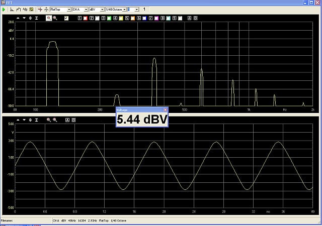
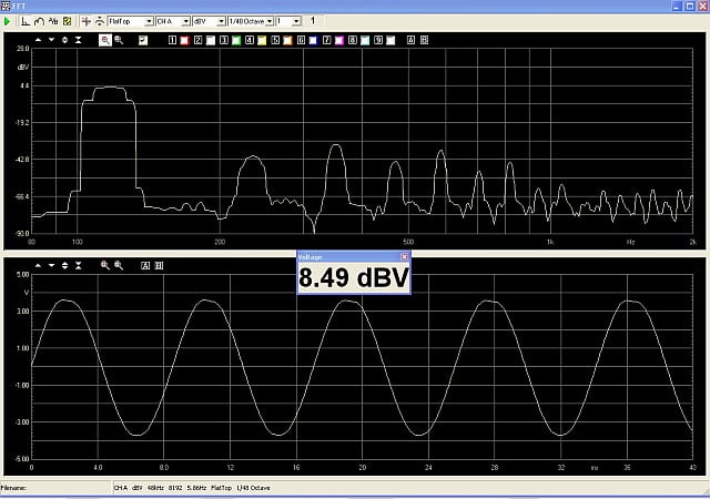
High level of 3rd Harmonic Distortion due to the Magnetic core of the 5.6 mH inductor
With the Clio Meter maximized, the THD measures 6.9% and IMD measures 1.2%. As can be seen from the measurement above, the distortion is symmetrical, as expected, so the dominant distortion is 3rd harmonic, with 2nd harmonic low. The waveform is starting to take on the form of a triangle wave as a result of the changing impedance of the magnetic core choke.
Well, perhaps this distortion is a result of the amplifier being driven so high? Let's test that. Since I do not have an air-core choke this large, I construct one out of two 2.4 mH cokes, stacked one on top of the other. It ends up being 5.7 mH. (The reason two 2.4 mH chokes add up to more than 4.8 mH, is due to mutual, not self inductance). This is why you do not have a linear relationship between turns and inductance in a choke. (And why there are (6) different equations to solve for inductance on the Wikipedia page referred to earlier). If both of these chokes were wired in series and placed far apart, instead of stacked one on the other, they would in fact be 4.8 mH. Now, at 1.7 ohms, the DCR of our air core choke is considerably higher than the magnetic core choke which measures only 0.28 ohms. This increased resistance requires us to deliver 115 volts to the series circuit to achieve the same 60 volts (62 V) across the 4 ohm test resistor.
The measured response is below:
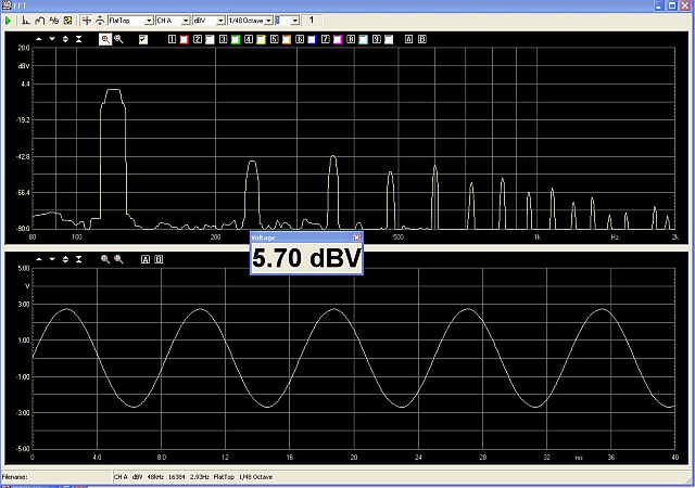
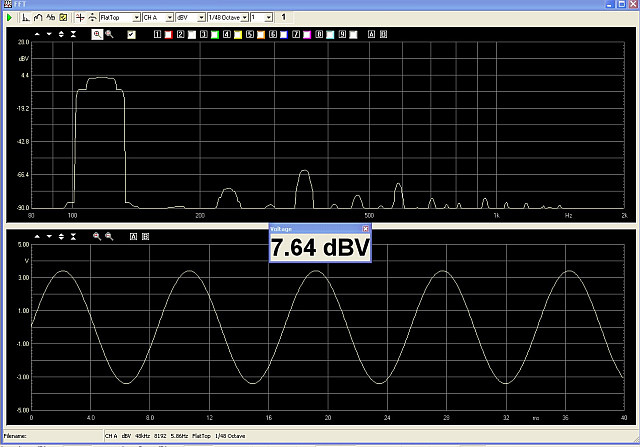
The distortion Products from the combination of Amplifier and 5.7 mH Air Core Choke
The distortion measured 0.952% THD. As can be seen above, the spectrum across the resistor looks quite different when driven through the air-core choke than it does when driven through the magnetic core choke. The oscillogram too looks free of distortion as well. So, let's ask ourselves, is this better because the DC resistance is higher by 1.5 ohms? Maybe the issue was current limitation in the amplifier. This amp is rated to deliver 3000 watts into 4 ohms, which requires 27.3 amps RMS. The 62 volts across 4 ohms only requires 15.5 amps RMS, just a little more than half what the amplifier should have available. Maybe the 45 degree phase angle between voltage and current at 120 Hz is straining the amp? What is the limit of this amplifier? Let's see. Without a series choke, with the 4 ohm load alone attached to the amplifier, I drive the amp to clipping, and measure 88 volts RMS across the resistor terminals.
The following measurement data was taken.
Amplifier in Clipping
As can be seen here, the sine wave is clipped, as the top of the waveform is flattened. Since we were able to deliver 115 volts unclipped to the higher load impedance, we have to assume this amp has run out of current. At 88 volts RMS, a 4 ohm load will draw 22 amps RMS. Close inspection of the amplifier specification claims 3000 watts @ 1% THD when bridged into 4 ohms but only at 1 kHz. Clearly at 120 Hz, this amplifier has clipped at 1936 watts. As had been said before, trust but verify... So, lets drop the input by 1db, and measure the signal across the resistor again.
Amplifier 1 db below Clipping - No Choke
This time we manage to get 80.6 volts across the resistor, with very low distortion. Clearly with a zero phase angle, this amp can deliver 20 amps RMS and 28.3 amps peak without clipping into 4 ohms. We can be pretty confident that the difference we have measured is the result of the magnetic core of the choke, and not the amplifier or signal generator. Suppose we drop the input drive to the magnetic choke to 6 db less than the 900 watts RMS delivered to the test load. Lets say we drop the voltage down to 28.5 volts RMS, or 203 watts RMS. What kind of distortion will we measure? Lets see..
6 db below clipping with Magnetic Core Choke

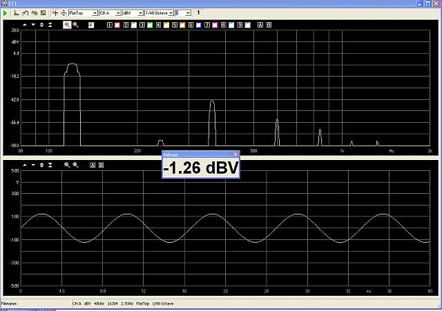
Even at 6 db below clipping, the Magnetic core choke results in more than 1% THD
While the waveform looks pretty clean, we see the same distinctive line up of harmonics, with 3rd being very dominant. When metered, the distortion at 25.5 volts RMS measures 1.3%. This is still higher than 0.952% THD measured with 62 volts across the resistor, and 115 volts from the amplifier using the air core choke. At this point we are well below the limitations of the amplifier, and delivering a current of 7.125 amps RMS, less than half as much current (1/4 the power) as was delivered through the air core choke and yet despite our reducing the power to 203 watts RMS, we find we have more THD in our resistor than what was present at 961 watts when driven through the air core choke.
The use of magnetic cores in chokes is a two edged sword. While magnetic materials in chokes will reduce size, cost, and the DCR of the choke, it comes with a disadvantage in terms of distortion. While amplifier manufacturers are busy reducing their distortions to numbers well below 0.01%, loudspeaker manufacturers still struggling to build systems which can play at or below 1% distortion anywhere at or near their output limits. To add an additional 1% distortion by using magnetic core inductors in series with the speaker is a price I am personally not willing to pay.
So, what conclusions are to be drawn from this article?
- Temperature is an enemy of all three components, and temperature has real and measurable effects upon the transfer function of the crossover network (and your music!)
- Using Nichrome as a resistor material provides a huge advantage over copper or aluminum by virtue of its relative constancy with temperature fluctuation
- Electrolytic Capacitors suffer hysteresis effects which can negatively impact audio
- Bypass caps can be used to improve performance of Electrolytics by lowering ESL
- Electrolytic Capacitors suffer from high dissipation, which cannot be minimized without using multiple capacitors in parallel
- PCB layout is an important consideration and effects the overall crossover power handling and performance, and is especially important in terms of heat and inductive coupling
- Saturation is not a digital phenomenon - It happens gradually and the magnetic core choke increases distortions at levels considerably below those at which the cores will "Saturate"
- Magnetic Cores can reduce crossover cost, DCR and size by increasing inductance
- Magnetic core Inductors are inherently nonlinear, even before saturating
• Air cores chokes are preferable, but suffer from high losses and high cost
While this is not an exhaustive study of chokes, or of every type of magnetic core material, we have seen how the use of a non-linear material can affect the sound of the music we hear. If we are looking to improve our systems, and purchasing upgrade crossovers, we need not only be informed about the specifications of the parts used in them, we also need to consider the PCB layout as well. While perhaps the simplest electrical circuits in use in audio today, crossovers can play a major role in the sound we hear coming from our speakers, and our speakers are the most important link in the audio chain in the vast majority of high performance home theater systems. The sum of the parts and their quality truly does matter, especially if you're a golden ear and desire the very best performance.
Paul Apollonio is a Southern California based consulting engineer, with 25 years of experience in the audio industry designing loudspeakers and crossovers. He may be reached at papollonio@yahoo.com and his resume and profile viewed online at http://www.linkedin.com/in/paulapollonio.