
Trading SPL for Extension in Subwoofers - A Current Trend?
JL Audio
More often than not consumers are swayed by a single parameter in a products specifications to judge its true performance. Car enthusiasts often judge a car solely by its 0 – 60 MPH acceleration time. Home theater enthusiasts tend to get caught up in “how many watts” their amplifier can deliver without really understanding the meaning of the spec or the trade off the manufacturer may have committed to yield higher perceived power at the expense of fidelity. The same often happens with subwoofers. Lately it’s quite a popular trend on the AVS and Audioholics forums of people critiquing a subwoofers performance by a simple metric; its -3dB point or how low the subwoofer can go in frequency before its sound output rolls off. This article will explore the trade offs associated with tuning a vented subwoofer system for the lowest achievable frequency output and demonstrate a balance between real usable extension and efficiency for achieving the best performance given a particular driver size and box enclosure.
Let’s suppose you need to design a 12 inch woofer for a 2 cubic foot vented box that must withstand 250 watts rms. When you ask yourself, “How low should it go?” how do we decide? We can use a computer program to model the system, but with a blank page to start with, what factors come into play that influence our decisions?
A loudspeaker system is actually like a high pass filter. This is in short, the underlying basis for Thiele-Small parameters. The mass and stiffness of the speaker, size of the box and the diameter of the cone dictate how much efficiency you can get versus frequency. For the modeling of these systems, I used Harris Technologies Bassbox Pro, version 6.
If we look at the following specifications and are asked to judge which system is better, what should we conclude?
|
|
System “A” | System “B” |
| Woofer Size | 12” | 12” |
| Fs | 20 Hz | 20Hz |
| Box Type | Vented | Vented |
| Box Size | 2 cubic ft | 2 cubic ft |
| -3dB LF pt | 44 Hz | 32 Hz |
Clearly here the woofer which can go lower seems to be the better of the two. But you do not have all the information yet.
| System “A” | System “B” | |
| Woofer Size | 12” | 12” |
| Box Type | Vented | Vented |
| Box Size | 2 cubic ft | 2 cubic ft |
| -3dB LF pt | 44 Hz | 32 Hz |
| 1 watt SPL | 93.5 dB | 89.5 dB |
| BL | 16 TM | 20 TM |
In order to go down to the lower frequency without increasing the box volume, we have had to double the mass of the woofer from 75 to 150 gms, and we have also had to increase the magnet size substantially as the motor force (Gap flux in Tesla times the length of VC wire in meters in the magnetic field) has increased from 16TM to 20TM. (If the truck gets bigger and heavier, you need a bigger engine to move it about). Most importantly, in the search for more bass, we have not only driven up the cost, we have also lost 4db of output at and above 60 Hz! In fact on inspection of the curves, these two systems are equally efficient at 42 Hz, the low note on the bass guitar!
Now if you had an amplifier, and were given the choice of response down to 44 Hz and 250 Watts RMS or response down to 32 Hz with 100 watts rms, which would you choose? Well, this is actually the same tradeoff; 250 watts IS 4 db more than 100 watts and 4 db is substantial!
Now let’s say you have finished both speakers so we can pick the one we like the best. NOT ENOUGH BASS! You cry, let’s make it go down to 20 Hz! Can I make the box larger I ask! No, you say, it needs to fit in the back seat of my Volkswagen Beetle, so 2 cubic feet is all you get! (I am not making this stuff up… I have actually had this conversation).
Let’s take a look at these 3 designs, and see what trade-offs we have made in each to accommodate the need for bass extension. All 3 designs have a woofer with a 20 Hz resonance that is put in a 2 cubic foot vented box. The differences are shown in the table below:
| Parameter | System A | System B | System C | System D |
| Fs | 20 Hz | 20 Hz | 20 Hz | 20 Hz |
| Mms (Mass) | 75 gms | 150 gms | 300 gms | 150 gms |
| BL (motor force) | 16 TM | 20 TM | 24 TM | 20 TM |
| Xmax@500W | 8mm @60 Hz | 9mm @46 Hz | 11mm @31 Hz | 12mm @32 Hz |
| Box Tuning | 42 | 32 | 21 | 20 |
| -3 db point | 44 | 32 | 22 | 43 |
| 1 watt SPL | 93.5 | 89.5 | 83.9 | 89.5 |
| Flat? | Yes | Yes | Yes | No (droop) |
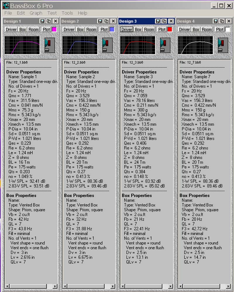
Below the table is the full set of parameters of the three speakers used in this comparison.
The first curve below is a “Normalized” amplitude plot.
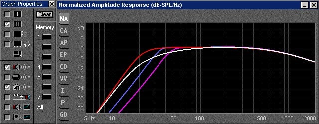
This graph gives us an idea of the low frequency extension, but tells us NOTHING about the efficiency of the woofer.
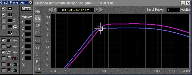
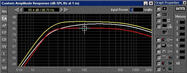
The next graph is the same set of curves, but it shows us in perspective the relative efficiency versus frequency of the woofer.

As you can clearly see from the 1 watt curve, there is a 9 db difference in efficiency between the 75 gm and 300 gm woofer in favor of the lighter woofer. Bear in mind also that the 300 gram woofer would have to have a much larger motor on it - (16 TM vs. 24 TM (TM = Tesla*Meters) for the heavier woofer). So not only is the heavier woofer far more expensive to make, it requires 9db more amplifier power relative to the lighter woofer from about 60 Hz up. In short, if the 75 gram woofer has a 100 watt amp, we would need 800 watts for the 300 gram woofer to make similar SPL’s. The woofer shown in the white and blue curve is actually the same speaker in the same box. The difference is the tuning of the box. Without a speaker change, tuning the box lower simply creates a droop in the response. In short, the gains below 30 Hz are paid for by the losses between 30 and 100 Hz.
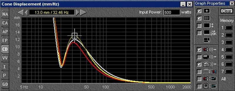
Now in addition to the larger magnet we will need to control the higher moving mass of the heavier woofers, this problem gets exacerbated by the need to move much farther when reproducing ever lower frequencies. Let’s take a look at the Cone Displacement curve of all these woofers, in the same box, driven by the same power. Remember, because of the efficiency differences between these woofers, the same power does not yield the same SPL’s. The heavier speakers are not going to produce the same SPL with the same power applied.

As we can tell from the curve above, the minimum excursion frequency of the system (below about 100 Hz) is the frequency where the box is tuned, so the port, not the woofer cone is doing all the work. Below the port frequency, the cone excursion increases rapidly. (Below the port tuning, the port is no longer a resonator, it is simply a hole in the box, and the air coming out of the port is out of phase with the air coming from the woofer cone.) The general trend is that lower tunings require greater excursions to be made before the port excursion relief is exercised on the woofer cone. As a result, the peak excursion is higher for those systems where the box is tuned lower. At the 500 watt level, we can see by comparing the blue vs. white curve (which is the same speaker in the same sized box, but two very different tunings) that the lower 20 Hz tuning has a far greater excursion requirement under real world conditions than the speaker with the 32 Hz tuning. This 2/3rds of an octave extension requires 1/3rd more peak excursion of the speaker. If in fact this additional mechanical travel is not available, then the speaker may well end up bottoming, and in the worst case, destroy itself.
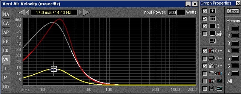
The other issue arising with a lower and lower designed F3 point, is one of dynamic range. Remember the loudness of a sound is not independent of frequency. With human hearing, the lower you go, the more output is needed for a given degree of loudness. So even if I could make a small speaker flat to 20 Hz, how do I get a sufficient dynamic range at that frequency with a limited mechanical travel? Put another way, if my sensitivity has dropped down to 80db for 1 watt, (not much above the threshold of hearing at 20hz) and I need to create 110 db of sound at 20 Hz to have a dynamic range of 30 db at that frequency in my listening room, that means I have to be able to put 1000 watts at 20 Hz into my speaker without it bottoming. Now if the speaker is ported at 20 Hz, I may not be worried about the cone excursion at 20 Hz, but what about the air velocity through the port? Beyond a certain limit, the air from the port becomes turbulent. This can result in both high distortion and literally negative gain from the port, when the air flow goes from being in phase to being out of phase! (I have measured this phenomenon. While I put in more power, the SPL near the port frequency actually goes down!) Now let's look at the vent velocity vs. frequency for the different designs.
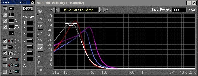
As we can see, the lower port tunings have a higher peak velocity at their tuning frequency. The reason the curve lines go from being light to dark in shade is to indicate to the program user, you are in the out of recommended limit area. In short, this port is running out of gas before we get to the 400 watt drive level. (The colors of the curves are the same in all the different performance graphs. That is to say, the blue, or white, or red, or pink curve represents the same woofer/box combination from graph to graph).
Let us assume, we have gone to great lengths to make the port large (you have folded it inside the box). It is large enough to accommodate the substantial air flow needed at 20 Hz. The vent velocity shown above is for a 2.5 inch diameter port, the largest that would fit into a 2 cubic foot box of realistic dimensions. For those of you who have not had the chance to read the original paper of Neville Thiele (you know, as in Thiele-Small parameters) the advantage of a vented over sealed box is about equal to a 1/3rd box volume reduction. If the port is more than 1/3rd of the box volume, it seems to me, the advantage of the vent disappears at that point. Ignore that for the moment, and lets look at the driver excursion at 40 Hz, a frequency much more likely to be excited (by the kick drum, tympani or low note on the 4 string electric bass guitar). The two designs ported at 20 Hz, and shown in the cone displacement graph as the red and white curves, have excursions at 40 Hz of 11 and 12 mm. Note this is substantially higher than the 8-9 mm excursions required of the other two designs. If these 20 Hz system woofers require longer excursions AND higher BL (motor force), that means the VC wire must grow larger in diameter and the gap to accommodate this wire also needs to be bigger. This is happening at the same time that we are putting fewer turns (L) in a magnetic gap (which gives us the flux or B). Suddenly the magnet and top plate and T-yoke (speaker motor parts) have gotten very, very large, heavy and expensive. (There is a reason why the bass drum is bigger and heavier than the snare drum).
Lets try one more design example before we put this all to bed. Lets say we can make the box 8 cubic feet, and the speaker 15 inches in diameter. What kind of speaker can we come up with to make our 20 Hz subwoofer.
I start with a speaker I used in my College senior project, the JBL 2235H. I then do a very little bit of massage (lower the BL and increase the mass slightly) so that this driver gives me a passively flat response in the 8 cubic feet I randomly picked to house the subwoofer. (OK, I admit I have done this a few times, so maybe it's not so random).
First item of note is how the sensitivity of the 15 inch woofer in the 8 cubic foot box is (at 100 Hz) 92 db while the 300 gram 12 is 85.5 and the 150 gram 12 is 89 db. Right away we have picked up 3 – 6 db of sensitivity. Good thing. Now lets look at the cone displacement.
Oddly enough we see that the 15 inch speaker is moving more than either 12 inch speaker. While this may seem counterintuitive at first, we have to remember this model retains that 3-6 db of sensitivity advantage over the 12 inch speaker. So while the power going in is the same, the output is far from it. The result is the requirement of 1-2 mm more excursion at the worst case frequency of 32 Hz. Since our 15 inch speaker has such a large box to work in, we get away with only 18 TM of motor force while the 12's require 20-24 TM by comparison! So far the idea that bigger speakers NEED more power is not faring too well. In fact the opposite is true. The bigger speaker in the bigger box actually needs less power to produce a given SPL. (Even when the mass is 40 grams higher than the lighter 12 inch speaker.)
But what about the vent? Well, since the port goes all the way down to 20 Hz, we can (and should) use a much larger port area (18 inches by 2 inches). In fact the larger port has a maximum velocity below 20 Hz, down at 14 Hz. Still, we are at less than 1/3rd the velocity of either 12 inch box, with their much smaller ports. The port on the large box in fact, takes up nearly an entire cubic foot, half the entire volume of the smaller box. The bass drum is larger than the snare drum. The acoustic bass is bigger than the acoustic guitar, and the trombone is larger than the flute. There is a reason.
If not terribly obvious, the compromise in the larger box will be sales. Back in 1978, in an Audio magazine article written by WJJ Hoge he relates a story from a serviceman overseas who had read his prior article on how to build a 21 cubic foot subwoofer. The serviceman wrote, “When I explained to my wife the meaning of 21 cubic feet, she explained to me the meaning of divorce.” Physics is not the only thing which never changes.
Conclusion
 In conclusion, there is
a price to pay for bass extension that does not come at the cost of increased
box volume. That cost is in both loudspeaker sensitivity and in the cost of
materials. With a fixed budget, the requirement of extended bass may be nearly
impossible given the necessity for a speaker of higher mass and motor force.
When one also takes into account the additional burden of excursion and the
distortion associated with increased Xmax, it becomes apparent that speaker
design in box volumes that are not unlimited in size and cost is a matter of
trade-offs and compromises.
In conclusion, there is
a price to pay for bass extension that does not come at the cost of increased
box volume. That cost is in both loudspeaker sensitivity and in the cost of
materials. With a fixed budget, the requirement of extended bass may be nearly
impossible given the necessity for a speaker of higher mass and motor force.
When one also takes into account the additional burden of excursion and the
distortion associated with increased Xmax, it becomes apparent that speaker
design in box volumes that are not unlimited in size and cost is a matter of
trade-offs and compromises.
When doing comparisons of woofers or subwoofers by
looking at specifications, remember that published specifications are almost
always static measurements, and usually only reflect what a speaker does at low
drive levels, where speakers tend to be linear and well behaved. In order to
get a complete picture of the performance of a speaker, one would need far more
information than is generally published on them. For subwoofers in particular,
sensitivity figures are often misleading as it is common practice to use the
efficiency number from Thiele Small calculations, and this number is generally
indicative of what a loudspeaker will do at the eventual place it will level
off (the pass band in filter-speak). For subwoofers, this is often at a much
higher frequency than 100 Hz, and is NOT indicative of what the speaker does
below 100 Hz, where you intend to use it. Also bear in mind that the parameters
on which these computer models are built often base their predictions on the
speaker being invariant in those parameters, while in point of fact the
speakers parameters are anything but constant and will change significantly
with both temperature and excursion.
The best way to evaluate the low frequency performance of a subwoofer or woofer is to listen to it, preferably at high levels with very low frequency content. If you can push the system into audible distortion, you have a better idea of its limitations. If one is looking for the low frequency cutoff of a loudspeaker, bear in mind that not all manufacturers calculate or measure it in the same manner. Some will cite the point at which the output is at half power (-3db) and others will use the point at which the speaker is at -10 db. Judging a speakers performance from specifications alone, is risky, especially when not all manufacturers are completely honest and forthcoming about what the speaker can do. Assuming you are a careful and critical listener, YOUR EARS are likely the most reliable instrument in determining the quality of the speaker.