
Loudspeaker Drivers: Identifying Legitimately High Fidelity Parts
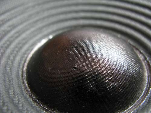
Audio Technology Driver
Originally Published: May 29th, 2012
In this continuing series on defining Legitimately High Fidelity Loudspeakers, we have discussed the following topics:
This article is dedicated to the actual loudspeaker drivers themselves (ie. woofers, tweeters, midranges, etc). Let us first define what a loudspeaker driver is and what its primary role is. A loudspeaker driver is an electromechanical device that converts electrical waves (music is more than impulses) into mechanical vibrations which in turn produces audible soundwaves. The size of the diaphragm will determine the bandwidth in which the loudspeaker will be most efficient at reproducing sound. A bass driver (usually 8” or larger) is designed to reproduce low frequencies (20-500Hz), a midrange driver (usually 3” to 7”) is designed to reproduce frequencies above 100Hz to 4kHz and a tweeter (typically 1” or smaller) is designed to be most efficient at reproducing high frequencies (ie. 1kHz to 20kHz).
Do Exotic Driver Materials Make Speakers Sound Better YouTube Videos Discussion?
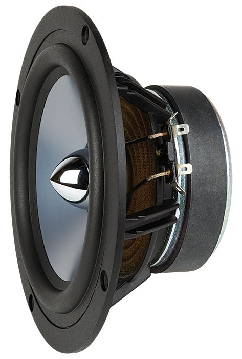
The Basics in Loudspeaker Driver Mechanics
It’s important to understand how a basic loudspeaker works so we’ve included a basic diagram of a typical woofer with all the major components labeled.
Loudspeaker Diagram – Courtesy of Polk Audio
The loudspeaker is broken into several parts:
- The Diaphragm (aka cone or dome) - the actual physical surface area of the driver that moves up and down from the voice coil interaction with the permanent magnet, thus producing sound by compressing and rarefying air, thus creating sound waves. (sound is not “moving air” it is propagating pressure fluctuations.)
- The Dustcap (optional) – located at the center of the cone and covers the voice coil and can increase rigidity of the diaphragm and most importantly in seals the diaphragm.
- The Basket (aka. Frame)– the physical structure that holds the entire driver together
- The Voice Coil – basically a wire coiled around a bobbin (electromagnet) at the center of the speaker and attached to the spider. When current flows through the coil supplied by the amplifier. it produces a temporary magnetic field when a signal is applied to interact with the permanent magnet (++ oppose ; +- attract). Where extra bobbin strength is needed, a collar can be added to that portion of the bobbin not covered by the coil.
- The Spider (aka. Damper) – Two prime functions of the spider, in conjunction with the surround, are to center the diaphragm, and force the forward and back movements of the voice coil to be linear, so that the coil does not scrape the narrow magnetic gap. The Spider provides the primary restorative force in the suspension being ideally placed close to the motive force, the voice coil. Linearity of a drivers suspension (and hence compliance) is critical and a lot of research has gone into designing spiders with the necessary stiffness and linearity, and designed not to add structural resonances of their own. The compliance of the spider & surround helps determine the low frequency limit of the drivers useful bandwidth, specified by the well-known free-air resonance (fs) parameter
- The Suspension (aka. Surround) – typically made of cloth, butyl rubber or foam, attaches the diaphragm to the driver basket and in conjunction with the Spider, helps to control and dampen cone movement. In some cases there may be more than one spider and in some cases (tweeters) there is no spider. In woofers, the surround is necessary to simply hold the edge of the cone in place and, along with the spider, to ensure linear in and out movement of the voice coil. It also functions as a mechanical termination for the radial traveling waves in the cone (cones do flex!) where it can dampen standing waves that will occur. The stiffness of the cone material is a factor in determining the frequencies at which resonances occur - higher being better, but at least outside the intended operating frequency range.
- The Permanent Magnet – a fixed DC magnet which is part of the motor structure affixed to the basket of the driver creating a stable magnetic flux across the annular gap which the voice coil sits in.
- The Phase Plug (optional) – similar to the cone but typically looks like a bullet. Its purpose is three-fold, to reduce moving mass and on-axis beaming and also serve as a heat sink and to a smaller extent offering venting.
- The Vented Pole Piece (optional) - this is a hole located in the center at the back of the permanent magnet to help reduce air pressure under the dust cap and cool the voice coil.
To generalize a bit more, the magnet assembly of a loudspeaker consisting of a top plate, bottom plate and pole piece, voice coil and magnet can be considered the "motor structure".
This Polk example appears to be quite a heavy duty driver as evident by how much venting and free air-flow they are incorporating into the design. This is the type of bass or midrange driver you typically see in more expensive speaker systems that are able to sustain high output levels with low distortion and low compression. More budget-oriented designs typically won’t have vented pole pieces, which will limit how much thermal energy they are able to dissipate at high output levels, thus potentially causing more compression.
Check out our recently added YouTube Video discussion on Loudspeaker Driver Science with Shane Rich, Technical Director of RBH Sound to supplement this article.
YouTube Video Discussion: Loudspeaker Science: Identifying Good Speaker Design
Cast vs Steel Stamped Driver Baskets
Loudspeaker driver baskets are typically constructed either of stamped steel, plastic or cast aluminum. Plastic baskets are generally used solely for cost savings over cast, or heavy gauge stamped frames. They are fine for smaller driver applications (6” or less) but are usually not used for larger and heavier bass drivers where greater durability and rigidity is needed. Though there are exceptions. A well designed molded plastic basket with glass fiber can provide better acoustics than both stamped and cast aluminum. The plastic can be designed by geometry and with fiber fill to have adequate rigidity, and it offers the benefit of damping any residual parasitic vibrations. Since stamped and cast baskets are more commonplace in the industry, we will focus most of the comparisons on these two type of frame options.
Here are the facts about cast aluminum vs. stamped steel frame speakers. Aluminum is paramagnetic. That means it is not entirely NON magnetic, as its permeability (let’s call it ‘desire to carry magnetic lines of force’) is about 5% higher than air. Steel on the other hand, is hundreds of times more willing than air to carry magnetic lines of force, the same way copper carries electrical currents, with ease. The result is that the very attachment of the steel to the top plate (part of the magnetic circuit into which the voice coil is immersed) guarantees the amount of magnetic force in the gap will be reduced by the parasitic flow of magnetic lines of force into the steel frame. However, much of this can be alleviated by moving the basket away from the frontplate by using a plastic, paper or other non-magnetic spacer. Good driver designers know and do this when dealing with stamped frames. In reality, flux leakage though the basket typically isn’t a huge deal unless you are designing pro drivers that need every bit of efficiency possible. But we included this point in this article to be as thorough as possible when comparing various basket types.
Still, I can imagine some of you asking, why not use stainless steel instead of regular steel? Good question. Two reasons: 1. It is much harder to form it by pressing (stamping) and 2. It is much more expensive than soft steel.
Stamped woofer basket (left pic); Cast basket woofer (right pic)
A significant advantage of aluminum over steel is the way in which it effectively draws off heat from those parts of the driver that surrounds the voice coil that get heated most quickly, such as the top plate. (remember, the top plate is directly attached to the speaker frame, so this physical coupling will result in the transmission of heat between the parts.) Since most cast aluminum frames are several times thicker than the steel ones, and since aluminum is an ideal material for heat sinking (it is what most heat sinks are made of), it will also let the speaker run cooler for a given amount of current feed into the voice coil. In addition, it will allow a larger amount of current to be put into the voice coil by drawing away and dissipating the heat more efficiently than steel can do. The ONLY reason to use steel instead of aluminum for a speaker frame (and it’s a legitimate reason) is cost. With the proper tool, a single punch can stake and swage (attach) a steel frame to a steel top plate in a second or less. No drilling costly threaded through holes for screws in the top plate is necessary. There is no need to buy the screws, or make sure they are glued in place or screwed down with the right amount of torque. Stamped steel is a far less expensive route for a big mechanized factory than cast frames are.
Cast aluminum frames, if properly designed, are always going to offer an advantage over steel frames, especially with respect to rigidity. That being said, you can still have well designed stamped steel frames. The basket material alone does not define the quality of the driver. Manufacturers building legitimately well-engineered stamped frames typically use thicker gauge steel than the one pictured above left. This increases rigidity and reduces susceptibility to ringing. You will find many of the high output budget subwoofers offered in the $1k or less price range employ thick stamped steel baskets. When trying to hit a target price point, while still offering respectable output and performance, this is a design compromise that often makes sense.
Editorial Note about Cast Aluminum vs Steel Frames by David Waratuke
The issue of stiffness in a driver basket frame is not one of steel versus aluminum per se, it is one of geometry and manufacturing. Steel as a material is actually three times stiffer than aluminum as indicated by a property call the Modulus of Elasticity, which for steel is around 29,000,000 pounds per square inch (psi) while aluminum is only about 10,000,000 psi; a modular ratio of 2.9. The lower stiffness in a steel basket comes from using stamped manufacturing that limits thickness of resulting basket as compared to what can be cast. This difference in thickness creates an exponential differences in the geometric component of the stiffness for the resulting baskets. It all comes down to the fact that a cast aluminum basket typically contains more aluminum, with the correspondingly increased thickness, than there is steel present in a typical stamped basket and that more than makes up for the aluminum being a softer material.
Additional Information about Cast Frames
Cast aluminum frames are made by pouring molten aluminum into a block of steel that has been hollowed out using a very precise computer-cutting (CNC) program. This process is known as tooling, and it is a central process in all consumer products made today. Whenever you see a nicely molded, shaped piece of plastic or metal, chances are it has been formed by some sort of tooling process. Tooling is very expensive, so much so that smaller manufacturers jokingly refer to the need to “tool” something as a four-letter word.
There are two basic types of tooling: Proprietary tooling and open tooling. Often proprietary tooling is copied, or the logo is simply ground off.
Proprietary tooling is tooling that that particular manufacturer designs and pays for themselves, and then they own the tooling and retain the rights to it forever. There are many distinctive tweeter faceplates, woofer frames, or plastic satellite cubes which we associate with a particular manufacturer’s look and style, and that’s because they’ve done their own tooling. The manufacturer will often protect their tooling appearance with a design patent, in order to make their design immune to counterfeiting and unauthorized copying.
Good examples of proprietary, patented tooling are Boston Acoustics’ automotive Pro Series cast aluminum woofer baskets and Bose’s famous satellite cubes.
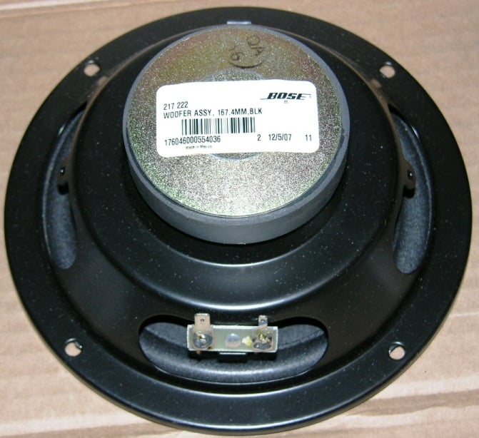
Boston Acoustics Pro Series Woofer (left pic) ; Bose mid woofer (right pic)
The other kind of tooling is what’s known as “open tooling.” Open tooling is tooling that a vendor of raw parts undertakes themselves in anticipation that many of its customers will order their parts, thus making their (the vendor’s) speculative investment in the tooling worthwhile in the long run. Examples of open tooling are the cast woofer baskets that many driver vendors make for their line of general distribution woofers, for example, or the round plastic frames for ceiling speakers offered by many Far East vendors to “brand name” speaker companies. You can look closely at the metal woofer baskets or round plastic ceiling mounting frames from many speaker companies and find that they are identical, absolutely identical.
There is nothing wrong with that, of course. The frame, top plate, back plate, and magnet are known as the speaker’s “hard parts.” It’s expensive for small speaker companies to tool and manufacture those, so they buy them pretty much “off the shelf.” The “soft parts” of a speaker—the cone, surround, voice coil, spider—are easier to customize and change from run to run, so that’s where a lot of differentiation comes in for the speaker companies. Brand A and Brand B may use the same basket, top plate and back plate, all tooled by Vendor C, but they specify and customize different soft parts, and the resulting woofers are completely different, each according to that particular company’s engineering design goals and marketing objectives. Again even unique custom tooled motor designs do not remain proprietary. They are copied. That's progress.
Rigidity of Cast vs Stamped Baskets
Regarding resistance to shipping damage, this is a real concern. In the early 1990’s when magnetic shielding was important for speakers in a home theater so as not to interfere with CRT televisions, many speaker manufacturers added “bucking magnets” onto their speakers’ existing magnet structures. This was another magnet, reversed, so its external magnetic field would cancel out, and then the entire structure was typically enclosed in a shielding “can” to further reduce stray leakage.
The problem was that now these speakers’ frames were being asked to carry significant added weight for which they weren’t designed. One major company was using a plastic frame and the additional weight of the bucking magnet and shielding were causing these frames to crack and break off during shipping. Another company was using stamped steel frames on their midranges, but the struts were not reinforced with crimped sections—they were flat and thus very prone to bending because of the added weight. The entire first shipment of these new speakers went out to the dealers and the mids were all inoperative, because the weight of the magnetically-shielded structures had torqued the frames so badly in shipping that the voice coils were all frozen out of alignment. Both of these companies redesigned their baskets with additional reinforcing ribs and added internal cabinet supports around the drivers to keep them from moving and being damaged in shipping. So there is no question that the added rigidity and precise alignment afforded by cast frames is their biggest advantage. Cast baskets tend to hold the parts in alignment more accurately and with greater longevity. It has been proven countless times that such baskets survive shipping drops better than stamped baskets.
Bottom Line on Driver Baskets
Stamped baskets are less costly to produce than cast baskets and are at a disadvantage in some aspects (strength, cooling, etc), but respectably good performance can still be achieved with stamped frames. You will typically find the very best loudspeaker designs on the market will take advantage of the properties of cast baskets and thus employ them in ALL of their drivers. Plus—cast-basket drivers look so darned cool when they’re photographed by themselves! Any speaker marketing department worth its salt knows that!
Identifying Legitimately High Fidelity Loudspeakers: Vented vs. Non-Vented Woofers
Turbulence Reduction, Cooling and more…
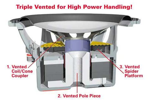
A vented pole is basically a hole bored out at the back of the motor structure as seen in the figure below. Its primary job is to reduce the highly non-linear spring effect of the air trapped behind the dustcap/dome, and reducing distortion at high excursion. There is debate on the effects of cooling with vented pole pieces as it actually can be detrimental if the vent is too large. Not only that, but the magnetic permeability of the pole piece can be reduced given the smaller amount of metal in the pole piece which can affect motor efficiency. These issues were much more of a concern years ago. However, with advent of driver modeling and design programs such as FINEMotor, a well designed driver with a vented pole piece can be very effective at balancing the needed effect of reducing pressure under the dust cap for improved linearity and still providing cooling for the voice coil. Let’s discuss this in further detail.
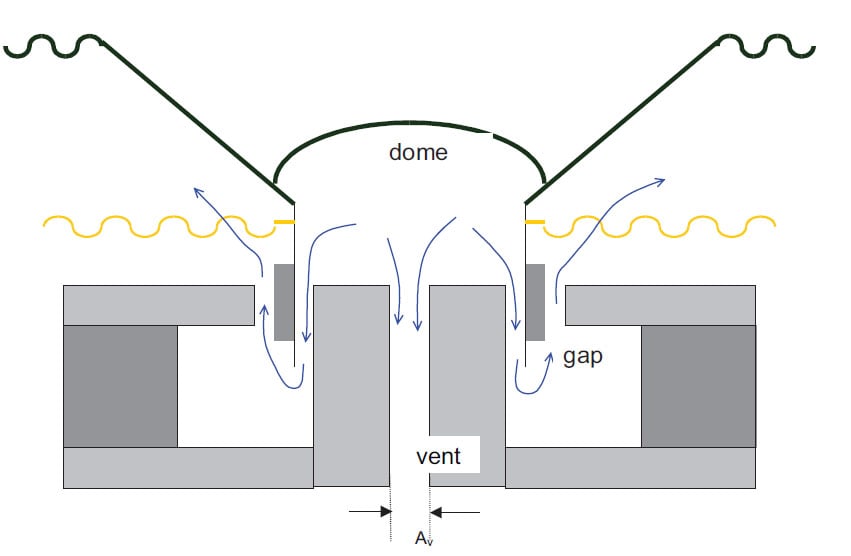
Sectional View of Driver with Vented Backplate (courtesy of JAES Vol 52, #1/2, 2004 Jan/Feb)
Reducing Air Turbulence Under the Dust Cap
A solid dust cap does not allow air to pass through its surface, and creates a small acoustic chamber that will generate air pressures as the cone moves back and forth over the pole piece. This compression and rarefaction can have detrimental effects on speaker operation which can sometimes be heard as a “squeaky wizzer” sound when the driver is really moving back and forth close to its excursion limits. With tweeters, this can produce what has been referred to as a “cupped hand” resonance. Since the area between the voice coil and pole piece is too small to effectively relieve this pressure caused by the motion of the dust cap, manufacturers use two practical solutions to the problem.
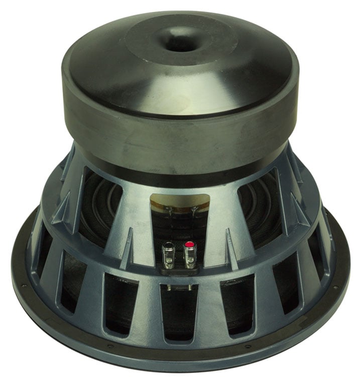
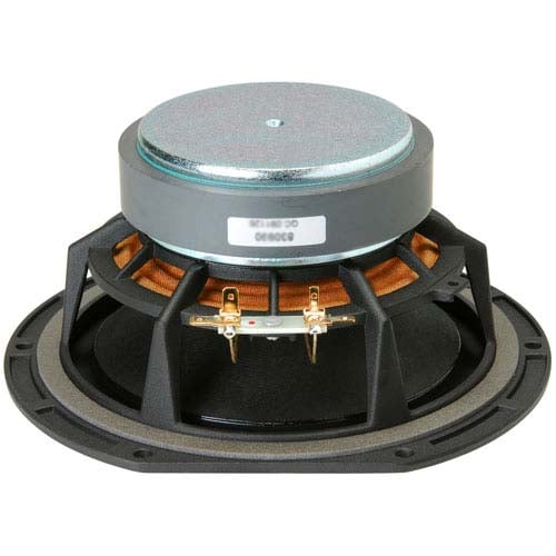
SVS PB13 Ultra Woofer (left pic) ; SVS NSD Woofer (right pic)
One (as previously mentioned) is to vent the pole piece, which requires a small hole to be drilled through the pole piece so that air can pass out an opening in the backplate. Another way of venting a driver is to punch holes into the voice coil former where it attaches to the cone. This will allow air to flow out of the small chambered area and relieve the pressure between the pole piece and the dust cap. Both options have their own merits and can really enhance the performance of a midrange or woofer as opposed to a similar design with no venting at all.
The above left picture of the SVS PB13 Ultra woofer shows a flared vented pole piece while the above right picture of the SVS NSD woofer shows the punched vent holes into the voice coil former and cone.
The Role of the Dust Cap
 We haven’t spoken much about the dust cap of
the loudspeaker diaphragm. Some argue
that it plays little to no role on overall performance of the driver, but those who really understand loudspeaker mechanics know that this generalization is
untrue. Years ago when drivers employed
soft lossy cloth dust caps, they did little to nothing to add rigidity to the
diaphragm. Their primary role than was
literally to block the dust from getting into the gap and also offer some
cooling for the voice coil by allowing air flow. Loudspeaker driver technology is a lot more
advanced these days and as a result, superior drivers are being produced and employed
by companies with a genuine design goal of producing better speakers.
We haven’t spoken much about the dust cap of
the loudspeaker diaphragm. Some argue
that it plays little to no role on overall performance of the driver, but those who really understand loudspeaker mechanics know that this generalization is
untrue. Years ago when drivers employed
soft lossy cloth dust caps, they did little to nothing to add rigidity to the
diaphragm. Their primary role than was
literally to block the dust from getting into the gap and also offer some
cooling for the voice coil by allowing air flow. Loudspeaker driver technology is a lot more
advanced these days and as a result, superior drivers are being produced and employed
by companies with a genuine design goal of producing better speakers.
The dust cap does more than just protect the motor assembly from dust. A hard dust cap for a well-engineered driver acts as a stiffing membrane for the diaphragm. Hence it helps the driver act more pistonic as we discussed earlier. Inverted dust caps can further improve cone rigidity and reduce frequency response anomalies better than protruding dust caps, all other things being equal. The shape of the cone must also be factored into this equation but that goes beyond the scope of this article.
Beryllium Phase Plug Mid Woofer (courtesy of Status Acoustics)
Phase Plug Drivers
Phase plug drivers are a unique situation. They don’t have a rear vent for cooling. When a driver employs a true phase plug, meaning the actual plug is affixed to the motor pole piece of the driver and not the cone, it does several things:
- It can reduce the moving mass of the driver, thus allowing it to extend its usable frequency response
- It acts as a heat sink to cool the voice coil and increase power handling
- It slightly reduces on-axis beaming by dispersing the high frequencies the driver is producing
- It acts as a vent to allow airflow through the voice coil much like a vented pole piece
All things being equal, phase plug drivers have an advantage when used for upper bass and midrange applications, but also create a hole at low frequencies, thus reducing total cone surface area and the driver’s ability to effectively produce low frequencies. If not properly engineered, they can also increase mechanical noise when excessive air spills from the gap. You will typically find these used as dedicated midrange drivers more so than dedicated bass drivers for these very reasons. The Definitive Technology patented BDSS design addresses these concerns and allows phase plug drivers to be used as bass-mid drivers more effectively than many conventional designs.
Editorial Note about Phase Plugs:
Some loudspeaker manufacturers use a quasi phase plug which looks like a phase plug for marketing purposes, but does not physically separate from the cone of the driver. These "so called" phase plugs are really nothing more than fancy dust caps. They can help improve frequency response but in some cases, they can do more harm than good as they can provide an inconsistent surface area and also increase mass of the cone yielding poorer frequency response and linearity.
Editorial Note about Driver Beaming:
Because the diaphragm of the loudspeaker becomes increasingly directional at high frequencies and phase differences of high frequency signals owing to cone material, properties and geometry, it ceases to behave in a pistonic manner displaying high Q resonances. At low frequencies the diaphragm placed in a small enclosure, will radiate equally in all directions. However as frequency increases and wavelengths decrease, the driver will start to beam at approximately the frequency where the cone diameter equals the wavelength it is producing. This results in the speaker producing sound predominately in the forward direction. As frequencies increase, the beaming effect becomes narrower and narrower and more intense until finally all of the sound will radiate straight forward from the driver forming a beam having the same diameter as the driver diaphragm itself. This is one of the many reasons why bandwidth limiting the driver and handing off the higher frequencies to a smaller drive unit like a tweeter can resolve this problem.
Heat Management
Heat management and dealing with air pressure build up under the dust cap in a loudspeaker are important parts of the overall design. As mentioned earlier, the effectiveness of using a vented pole piece for heat management is still hotly (no pun intended) debated among driver designers, but many engineers designing pro drivers for high output and excursions are quite adamant of the positive effects it can have if properly executed.
We need to use steel to complete the magnetic circuit and make the speaker work! Unfortunately, steel makes a poor heatsink. The way that better speakers are made is often by using top plates that are considerably thicker than normal speakers. All the power being sent to a loudspeaker has to go through the voice coil at some point. Typically, 97 to 99 percent of the power is lost as heat. One additional way to manage the heating of the loudspeaker motor is by venting. If you have examined loudspeakers closely, you will notice a great many of those woofers, especially the woofers which use larger diameter voice coils, have a hole down the center of the pole-piece (hence the term “vented pole piece”. A vented pole piece is essentially a cylinder which goes through the center of a ring magnet to bring the north and south poles close enough to concentrate the magnetic force in the small air gap in which the voice coil is immersed. The reason for this is simple. As the voice coil gets hot (they can stabilize typically in seconds when hit with high power), the heat has to escape, or else the voice coil will simply burn up—not good. So the metal close to the voice coil (top plate on the outside, and pole-piece on the inside) needs to stay cool. If they don't, the heat won't escape the voice coil, and eventually it will simply fail.
If the speaker in question is a woofer, then under high power, it will undergo high excursions. This allows us to use the cone and dust cap as a pump, moving the air across the voice coil. Now moving the same air continually without any exchange won't help much. We want that air to be refreshed and exchanged with the air in the surrounding vicinity so that we can keep that voice coil (VC) from burning up! This is the primary reason why we have gone to the trouble and expense to cut a hole in the pole-piece. Its presence allows the exchange of hot air (unlike the halls of Congress, where hot air may pass without any real work getting done).
Another viable option of reducing heat build up in a voice coil is to directly couple an aluminum voice coil former and diaphragm. This effectively allows the actual loudspeaker cone to act as the heatsink. This type of design can be very successful at reducing heat. But, it doesn’t address one primary concern that a vented pole piece does, reducing air turbulence under the dust cap.
About 20 years ago, a well-known mid-line speaker company decided to enter the high-end market with a family of aluminum-cone speakers. The voice-coil former was aluminum, connecting directly to the aluminum cone, forming a continuous aluminum heat-transfer path. They were long-throw 1 ½-inch voice coils on smallish 6 ½-inch woofers, so the entire structure was pretty robust. During power testing one day late in the development cycle, they wanted to really “see what these babies could do,” as the saying goes. The gain was turned up louder and louder, and the speakers were really cranking, but not complaining. Someone touched the woofer’s cone, and it was hot! Then someone flicked a little water at the cone with their finger and it sizzled and evaporated like water hitting a hot frying pan.
Does an aluminum cone provide any heatsinking? Yes it does, especially when the voice coil former is aluminum also and is bonded directly to the cone. That was twenty years ago and the experience is still crystal clear. Of course, it needed to have such high power handling, because the greater mass of the aluminum cones made for a low system sensitivity of only 84dB 1w/1m.
Ferrofluid Cooling
Many tweeters these days employ ferrofluid cooling. Its purpose is three-fold: to conduct heat away from the voice coil, provide damping, and center the voice coil. Ferrofluid is an inexpensive and effective way of increasing short term power handling operated under normal conditions, and not when the tweeter is already pushed to its limits. The downside can be consistency in performance of such drivers when under high output load conditions. Also, over time, the fluid can dry out making the cooling it provides ineffective. Some designers engineer the loudspeaker crossover at low power levels, not realizing how the frequency response and damping can vary depending on how hard the loudspeaker system is driven.
It is possible to use ferrofluids in mid-range drivers and woofers. However, since tweeters tend to have the smallest peak power handling by nature, they stand to gain the most from the short term peak power handling increases provided by ferrofluid. Also the gap and coil in woofers is much larger often making it cost prohibitive and impractical to use ferrofluid cooling. There are many different formulations of ferrofluid available, allowing the designer to tailor the characteristics to achieve his/her desired design goals with less compromise.
Bottom Line on Driver Venting
Venting the pole piece of a woofer has significant advantages in reducing highly non-linear spring effect of the air trapped behind the dustcap and reducing distortion under high excursions. A secondary benefit of venting the pole piece can be heat dissipation, thus increasing the driver’s power handling and reducing its susceptibility to thermal compression. You will typically find the woofers and midrange drivers of the very best high output loudspeakers employing either a vented pole piece or hole punches in the voice coil former and/or cone to achieve the best possible performance. Phase plugs can also be a useful viable alternative to venting a pole piece or hole punching the cone/former.
Ceramic (Ferrite) vs. Neodymium Magnets
Since we know that acoustic interference is present from multiple sources (be they multiple tweeters, or the direct and reflected sound in a room) causing the same signal (read frequency) to arrive at the listener’s location at slightly different times, we can consider an ideal source (eliminating this multiple time arrival issue) that is infinitely small. We can stack up a large number of these very close together, they can sum without cancellation up to a very high frequency. Unfortunately, as we shrink the size of our loudspeaker, we also limit its ability to radiate acoustic power, which is based, in part, on the resistance of the air load to which it is coupled.
So, we have our dilemma. Everything is a compromise. Suppose we had a magnetic material which would allow us to make a small (say 25 mm or 19 mm) tweeter, and still have a sufficient amount of magnetic force to not starve the product of motor force (BL, where B =Tesla and L=Meters of wire immersed in B). Well, we have had exotic magnetic materials for quite some time, the most popular of which today is neodymium. The advantage of this product is that it contains about 10 times more magnetic energy per unit volume than does the much more commonly used ceramic magnet. This allows us to make the diameter of the tweeters very small. The smaller the faceplate, the closer we can mount the tweeters (or any speakers with a small diaphragm size) together. The closer we can mount them together, the higher the frequency to which they will act as if they were ONE speaker, and the less acoustical interference we will have to endure from the array. This advantage is not to be seen in 18” woofers. That said, if you are hauling about 50 boxes of them on tour with the band, the difference in weight alone can be offset by the decrease in your cost of fuel.
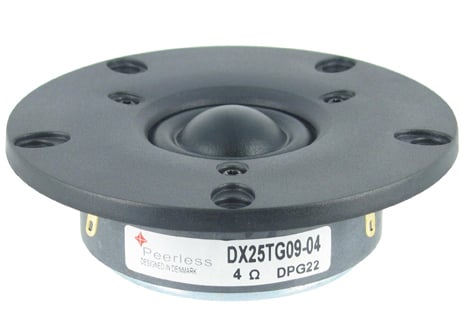
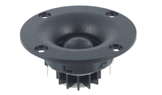
Ferrite Magnet Tweeter (left pic) ; Neodymium Tweeter (right pic)
The above left pic is of a ferrite magnet tweeter courtesy of Peerless. The above right pic is of a neodymium magnet tweeter courtesy of Vifa. Notice the heatsink on the Vifa tweeter to help keep the small magnet structure cool.
Neodymium has different technical challenges in its employment than do ceramic magnets. Most notably, as ceramics get hotter, they become more stable and harder to demagnetize (until they reach a point beyond where the entire speaker has gone up in smoke, called the Curie temperature.) While consumers need not concern themselves with this point, those in the professional business must and do. It is not uncommon, even in consumer parts today, to see a heatsink attached to a neodymium motor structure.
The reason is so it does not become demagnetized from the excess heat caused by great amounts of input power. The fact that the steel surrounding the neodymium is far smaller and therefore has less capacity to hold heat than the larger heavier structures required by ceramic magnet motors is another exacerbating factor when trying to use neodymium in higher powered loudspeakers. Some of the more clever manufacturers design their cast baskets with heatsink ribs that encapsulate the small neo magnet structure, thus giving the entire driver/basket/magnet assembly the same thermal heatsinking area of a traditional ceramic magnet driver. The Boston VR-M90 3 1/2” midrange from 1999 or 2000 was one such driver. It will be interesting to see the short term direction of the marketplace in response to recent tripling of the price of neodymium in China. Sadly in the last few years, small and light just got a lot more expensive, making neodymium a less practical choice when trying to shrink the size of the motor structure of a driver.
Bottom Line on Driver Magnets
Neodymium has the advantage of shrinking the weight and size of the driver motor structure but care must be taken in design execution to ensure the magnet is properly vented to avoid excessive thermal compression issues a ferrite alternative will typically not suffer from.
Identifying Legitimately High Fidelity Loudspeakers: Speaker Diaphragm Material
Now back to what we can see when we go shopping. One of the most salient features of any loudspeaker is its diaphragm. There is a lot of science and pseudo science surrounding the choice of a diaphragm material and what effects it really has on performance. One of those debates, which had been raging for decades, is about metal vs. paper or cloth diaphragms. Each has its merits, and everyone it seems, has their preferences. Let's discuss the basic function of the loudspeaker, and how the diaphragm is supposed to function, and what is actually happening in the “real world”.
An ideal loudspeaker diaphragm would never flex, thus it would exhibit perfect pistonic motion. It would always be infinitely rigid, well damped, and inherently in that characteristic, the speed of sound through the material would be infinite, thus the mass would ideally be zero and the break up mode frequency would be infinity. Loudspeaker engineers have a word for this ideal cone material. Unobtainium (apologies to James Cameron from Avatar).
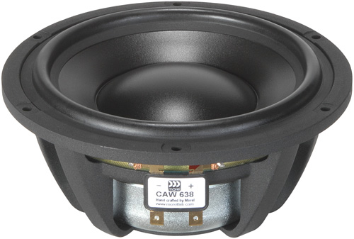
Treated Paper Woofer (courtesy of Morel)
Paper and Plastic Diaphragms
The best thing about plastic (“polypropylene”) cones, or whatever mysterious formulation or name the Marketing Department comes up with that month) is that they perform reasonably well and their manufacturing uniformity is very high, with pretty low cost. Unit-to-unit consistency with low cost is the ideal for any manufacturing concern, not just loudspeakers. Unfortunately, the need for constant incoming quality control is actually a downside to polypropylene cones. Poly cones have a major benefit in that they are highly damped and lossy. This means they can have a controlled break-up, which results in a smoother high frequency roll-off. Controlled breakup also can lead to a gradual reduction in Sd (projected area of the driver diaphragm) which reduces beaming compared to a rigid diaphragm. Some people argue that plastic cones tend to not sound as snappy or lively as stiff cone counterparts. This can be attributed to to an almost capacitive storage effect inherent in soft cone type drivers. However, if well engineered, good, well damped plastic diaphragms can excel at midrange frequencies and at a fraction of the cost of producing a quality stiff cone driver.
Paper formulations have all the good points spoken about above, but (depending on how/whether it’s sealed or not) the paper cone can actually absorb moisture from the air, changing its mass and damping characteristics. Cost, manufacturing complexity-uniformity issues, performance considerations, etc. make diaphragm materials selection a very difficult aspect of loudspeaker design.
Paper cones, made in part from felt and wool, for all their lack of sex appeal, have a combination of stiffness, low mass, and loss inherent in the material that often make the best sounding cones. If the cone can be made small enough, and stiff enough so that the problem area is above the region (frequency range) where the cone is excited, then light and stiff is the best way to go. If, on the other hand, you expect to cross over an 8 inch speaker with a 6 inch cone to a 1 inch dome tweeter at 2000 Hz (typical), then it is unlikely you will ever find anything affordable to do the job better than paper. Calling loudspeaker cones paper is a bit like calling everything that grows and converts CO2 into oxygen “vegetables”. Formulations are mixed and processed and doped with chemicals in a way where art truly meets science. All paper cones are NOT created equal.
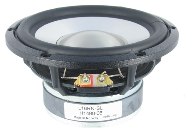
Aluminum Cone Woofer (courtesy of SEAS)
Metal Diaphragms
On the surface, it seems like Diamond or Beryllium would be the ideal obtainable material for a loudspeaker cone. Then, there is the cost to consider. So, how about a compromise? Aluminum can be made hard with alloys and heat treating (almost none of which is either ever done or done right) in the consumer marketplace. Aluminum is abundant, and relatively inexpensive. It is relatively easy to form and does an excellent job of dissipating heat. Since we actually want to sell this speaker, let's pick aluminum as a starting point. Now, the theory tells us that the speaker should never flex. It also tells us every time we double the weight, we end up making the speaker 6db less efficient. (Meaning we lost ¾ of our prior efficiency.) If the aluminum is too thin, then it won't be stiff enough. Too thick, then it won't be sensitive enough. So once again, our engineering choice is not the best of all worlds scenario, it is in fact another compromise. While it is true that making a diaphragm from metal has this advantage, it brings with it a disadvantage as well. Any standing waves on the cone will end up creating a great deal of ringing and flexing because what makes this material so strong (inability to flex) is also its downfall. What happens is that unless the diaphragm is indeed very small relative to the wavelength radiated, it will eventually flex. Unfortunately, when it finally does so, it will do it dramatically, and it will involve much of the cone in the process, which results in a rather significant peak or dip in the response and ringing. Ringing is bad for system linearity and sound quality. Minimizing this is a paramount concern for making a good sounding, and well behaved driver.
We can mitigate this problem by attempting to dope the cone with a chemical designed to absorb the sound waves, but then we are troubled again by the mass issue. It seems that the very thing we were trying to avoid at the start (compliance of flexure of the cone material) turns out to be a useful solution to the problem. While it will mean the diaphragm ceases to behave in a pistonic (acts as a uniform whole) fashion at a lower frequency, the compliance (accompanied by damping or loss) within the material tends to localize the disturbance of the standing wave to a much smaller area of the cone. Because less of the cone is involved in the “break up”, the impact on the frequency response is less pronounced. The peaks and dips are much less dramatic when they occur, and the point at which the cone stops making high frequencies and just dies (secondary resonance) is reduced.
The best sounding metallic cone speakers we’ve ever heard have never ignored the damping question, and most frequently combine metallic domes with lossy surrounds or an alternative material to impart damping to the cone. Back in the late 1980's, M&K Sound purchased raw drive units from both Eminence and Peerless (Denmark). One of the Peerless engineers named Knud Thorborg was asked by management to make a metal dome tweeter. He grumbled, and then finally caved in with a caveat. He would make it work, but it had to be done right, which meant essentially his way. Well, some people at Peerless were pretty upset with Knud. His way was 1 layer of aluminum, and 6 layers of “other”. Finally after beating him up in a dark alley (speaking metaphorically of course) they settled on 3 layers as a compromise. Now, while damping gets a lot of press, what is also true is that quite often the changes attributed to damping are often the result of differences in mass, stiffness, or geometry. All play a critical role in determining a loudspeaker’s tonal characteristics above the range where it is acting like a piston. Remember, if you cross over your 8 inch woofer to your 1 inch tweeter at 2000 Hz, the voice coil in the woofer has likely changed directions twice before the wave propagates up and to the end of the surround. When you use a speaker above its piston range (where it is basically an air pump) it behaves more like a transmission line than a pump. It is at this point in design, where tools like Finite Element Analysis (FEA) can be useful, as the simple Thiele-Small model falls apart. Though FEA is still a maturing technology and not ideal for cone development. Many loudspeaker driver engineers rely more on Klippel’s scanning vibrometer. This tool actually measures the displacement and velocity of the device under test. Essentially, anyone doing FEA without also using the scanning vibrometer to measure the results is relying too much on theory and not enough of real world.
It is challenging to make a driver good for both truly low and high frequency performance simultaneously. For one, any driver becomes more directional with increasing diaphragm diameter. This causes the overall sound to increase on axis, while it drops off axis at the upper range of the woofer, before it hands off to the tweeter. Another issue is woofer breakup, or “cone cry”, whereby the woofer cone itself resonates at a “favorite” frequency, typically located just above the cross point.
The designers will often make compromises in order to achieve a cost effective and pleasing result. A good rule of thumb is to cross the woofer over no higher than the wavelength of the cone diameter. So in the case of an 8” woofer with an actual 6.5” cone diameter, you’d want to cross it over at around (13,524 inch-per-second / 6.5”) = 2,080Hz. For a 10” woofer with a cone diameter of 8.5”, the highest crossover point should be around 1,600Hz. The problem with using such a large woofer in a two-way system is it forces the designer to use a higher cross point than the woofer would effectively be able to produce or a lower crossover point than the tweeter could handle without being overly strained (by power handling or distortion). For this reason, you don’t see many two-way speakers employing an 8” or larger woofer because the larger cone doesn’t effectively bridge that last 1/3rd octave gap to the tweeter. No matter how it is designed, no woofer can effectively reproduce more than 5-6 octaves without tangible performance issues. This is why multiple drivers are often used with specific design properties to play within their intended bandwidth and collectively work as one unit to produce full-range sound.
Tabulated below is a comparison of various metals utilized in speaker diaphragms. As we stated earlier, the ideal driver would be infinitely rigid and the speed of sound through the diaphragm would be infinite, while the material itself would have little or no mass. While no such material exists, we can get pretty close to ideal by having a material with a very low density and high propagation velocity.
| Material | Density g/cc | Velocity (m/s) | Poisson Ratio |
| Aluminum | 2.7 | 5,000 | 0.33 |
| BeAL | 2.1 | 10,000 | 0.14 |
| Beryllium | 1.8 | 13,000 | 0.08 |
| Diamond | 3.5 | 16,200 | 0.31 |
| Magnesium | 1.8 | 4,900 | 0.35 |
| Titanium | 4.4 | 5,200 | 0.30 |
Materials Comparison (courtesy of Harman, Inc)
A property that affects diaphragm break up is the velocity of sound that propagates through it. The higher velocity means an increased wavelength for the sound wave in the structure, or a higher resonant frequency for the structure, thus reducing the chance for destructive resonance under random excitation. Although the speed of sound is second to diamond, the first evidence of break up in beryllium is still above 50 kHz.
As you can see, pure Beryllium has the lowest density and hence the best Poisson Ratio (the measure of elasticity). Density is directly related to weight, and thus arguably a critical metric in determining the tweeter’s sound quality. When reduced power is required for a given output, the coil heats up less and does not alter the impedance of the tweeter, which minimizes dynamic compression and lowers distortion. Also power handling is improved. This is a major advantage for beryllium, as the density is by far the lowest of the bunch and almost half that of diamond! Theoretically such a material would be ideal for maximizing extension and reducing distortion and compression.
Pure Beryllium cones are expensive and out of the reach of most budget designs and also toxic if burned, hence why Aluminum often makes for a great alternative. For those that claim diaphragm material doesn’t make a difference, we’d argue that science disagrees.
The Infinity team developed a laminated Ceramic Metal Matrix Diaphragm (CMMD) material that exhibits Low mass, high velocity and high damping. It is deep anodized aluminum, where the anodizing (ceramic) penetrates up to 1/3 of the cone thickness. Check “technology” at www.infinitysystems.com. Lower cost products got a less aggressive anodizing, In the Infinity Prelude system for example, there were no breakup modes within the audible bandwidth. The material is now used in models from different Harman brands and in car audio systems.
Soft vs Hard Dome Tweeters
There has always been an ongoing debate about the sonic characteristics of tweeter dome materials. Do metal dome tweeters really sound "harsh," as some claim? Do silk domes sound, well, "silky"?
Different materials do have different physical properties related to diaphragm performance and these can and do influence the audible behavior of the driver. With full knowledge that many well-respected designers and engineers have opposing views and opinions on the subject, there are a few basic generalizations that can be made about different tweeter dome materials.
Soft vs Hard Dome Tweeters Comparison
Metal dome tweeters are generally constructed of alloys of either beryllium, aluminum or titanium. (All of which are chosen for their high stiffness to mass ratio.) They tend to have larger amplitude high frequency break-up modes than soft domes. Softer domes tend to have more break up modes which occur at lower frequencies than metal domes. When a metal dome breaks up, it does so much more dramatically than a soft dome tweeter which has the advantage of having more compliance and damping distributed throughout the dome. The more severe break up modes involve a much higher percentage of the tweeters surface area than a soft dome which tends to do a better job of localizing the disturbance, and isolating the other areas of the surface from the break up. The more dramatic metal dome break ups often will show up as a large dip and/or a narrow spike in the upper end frequency-response. There may be one or several peaks and dips which may be minimized by octave or fractional octave SPL averaging common to PC based measurement programs. Silk-dome tweeters tend to break up more often, but more gently. Some audiophiles feel that makes them more pleasing to the ear even when the break up mode is lower in the audio band than modes commonly seen in metal dome diaphragms.
The metal dome breakup manifests itself in the frequency response curve as a sharp peak, or a sharp dip in its usable frequency range. A quick glance at any credible published frequency response curve—such as those in Stereophile magazine-shows this behavior quite clearly. Interestingly, the ultrasonic peaks seen between 20-26 kHz are often accompanied by a depression in a metal dome tweeter’s response between 10-20 kHz. The May 2012 edition of Stereophile’s test report of the excellent Paradigm Studio 20 v5 speaker shows this classic metal dome FR behavior in Fig 4 on P. 103, as does the June 2012 issue, P. 117, Fig 5 of the Monitor RX6 with a "Ceramic-Aluminum/Magnesium" hard-dome tweeter. Perfect illustration, again.
So the "harsh" character often attributed to metal domes is not necessarily because of elevated frequency response levels in the highest audible octave (10-20 kHz). Since metal by its nature is not well-damped, (meaning the energy is not absorbed in the material) if a metal tweeter sounds harsh, it’s likely due to ringing or resonances in the dome that manifest themselves as audible artifacts, often times at frequencies lower than the curves would suggest.
Silk, treated cloth, polyamid, Kortec, Sonatex, are inherently better damped than single layered metal diaphragms. (The best metal dome designs get damping from their surrounds and absorption from acoustical treatments placed under the domes). Cloth and soft materials do not ring the way metal does, and the frequency response of a cloth tweeter is generally smoother. Soft domes with a lower and less resonant response roll-off at lower frequencies at the top of their usable bandwidth.
View Stereophile’s published frequency response curves and you’ll see this pretty consistently. In that same Stereophile June 2012 issue, P. 105 Fig 4 of the Joseph Audio Pulsar, the soft dome’s response is very flat—no suckout between 10-20 kHz like a hard metal dome—but you can see it beginning its rolloff at 18 kHz. (Not atypical for a cloth or silk dome of high quality). Not the highest audible frequency, but still very close and good enough for reproducing 98% of all musical content. It must be added that the voice coil mass and motor force and attachment are as critical for determining the top end of the tweeters response as is the dome material and mass. Heavy voice coils will not work properly to bring the top end of a tweeter up to a very high frequency limit.
Regardless of the dome material chosen, a lot comes down to the implementation of the technology and, overall, how the speaker has been designed. Another thing to consider is that ringing at lower frequencies in a tweeters bandwidth may result from the tweeter's motor being under damped. If a higher order high pass filter is being used on the tweeter it may also induce ringing unless it is critically damped. (Which is not what is typically used in filters. What is typically used are Butterworth filters which all ring at any order above the first). Ringing of this nature, indeed any low frequency ringing has nothing to do with the dome material but rather its mass, mechanical resistance, and its motor force.
There are excellent-sounding speakers using all kinds of tweeters. There are also hybrid dome tweeters that use a metal dome overlay over a soft material underneath in an attempt to get the best of both worlds.
In the end, the overall sonic character of the speaker has as much—if not more—to do with the designer’s voicing decisions and other design choices as it does with any single arbitrary tweeter dome material. What one hears in the highest frequency ranges covered by the tweeter is a complex combination of materials, geometry of the parts and the tweeter frontplate, the baffle, the grille, and the crossover network, even if we eliminate the clear contribution of the amplifier and source material. This can vary significantly from one angle to another. Often moving 30 degrees off axis will radically affect the response you hear in the top octave. There is NO guarantee that a resonance will produce a peak more than a dip. This is a 50/50 split. There is NO guarantee of the Q or amplitude of that resonance. These things will often confound confuse and surprise even designers that have done it many times before. The amount of small issues that can go wrong and create real audible measurable artifacts is large enough to warrant a chapter on its own.
Bottom Line on Loudspeaker Diaphragm Material
Stiff cone drivers are typically better than flexible cone drivers (all things being equal). However, no magic cone material alone will determine the quality of the sound or performance of the driver. Cone geometry and proper dampening of the cone material to better manage its behavior at and above its break-up mode plays a vital role in how the cone will sound. It's critical to avoid operating the drivers in their break up mode so a clear understanding by the designer through a properly executed crossover network is key.
Identifying Legitimately High Fidelity Loudspeakers: The Tweeter Resonance Frequency
One of the ways in which the designer may choose to create a smoother system response is by lowering the resonant frequency (Fs) of the tweeter. Since we all loathe to add mass to a tweeter for fear of killing the top end, the best way to achieve this lowering is by using a softer edge compliance. However, even with the edge very soft, the air behind the diaphragm will exert a stiffening force on the tweeter (just like the sealed box does for the woofer). For this reason, some designers will put a hole in the pole-piece, and enclose the back of the tweeter with a plastic housing to allow for a much lower resonance.
The holes in the tweeter’s neodymium coin magnet/back plate have to be reasonably large in order to engage the air behind it to reduce the stiffening effect of that air. Using a thicker neodymium magnet or doubling up on a standard-thickness magnet will compensate nicely for the loss of magnetic strength that results from the holes. Also, making that rear chamber out of, say drawn/ribbed aluminum instead of plastic will make the entire rear chamber’s surface area function like a heatsink and add very significantly to the tweeter’s power-handling ability. There is no easy, inexpensive way to do a good low-resonance frequency tweeter. You need a larger, more compliant surround for the longer excursions needed at 1500Hz compared to 3000Hz, and you need to have very robust power-handling/heat dissipation, since a tweeter tasked with reproducing full-strength signals at 1500Hz receives a far higher voltage drive through the crossover than a tweeter that only operates from 2500 or 3000Hz on up. It costs real money to make such a tweeter design which is why you typically only find them in the very highest caliber products. That said, all low Fs tweeters aren’t created equally. In speaking with a prominent loudspeaker designer, he was pretty vocal about his views that most low Fs tweeters he has measured didn’t have sufficient power handling, or motor or suspension linearity to handle the excursions needed to play below 1kHz. Though he admitted his testing was limited to metal dome designs and most designers would typically not cross a tweeter over that low to begin with.
While making the edge of the tweeter softer will often create issues of frequency response at very high frequencies, lessening the back chamber air pressure carries very little cost save for that of weight, and some magnetism loss in the circuit. (Caused by the loss of material in the pole-piece.) What you will find when taking apart tweeters made old school, is that the designer is placing damping material behind the diaphragm, very much like the treatment of the inside of a woofer box. Reflections from the metal, are very close to the dome, so with a wavelength short enough, a potential problem can be avoided by use of felt or foam.
At many of the of the speaker industry’s major companies, the prevailing design approach has been that it’s best to use a driver at least an octave above its resonant frequency. This tends to be the frequency range where its response is the smoothest and its distortion will be its lowest. The head of design at one company went so far as to mandate that tweeters were “always down 18dB at resonance.” In other words, when you ran the voltage curves of the crossover, the High-Pass section curve would have its curve be 18dB below “0dB” at the tweeter’s resonant frequency. Granted, this made for some pretty high tweeter crossover points and almost totally prevented the use of first-order HP sections, but as that company’s Design Head often boasted, “We hardly ever replace a burned-out tweeter under warranty!”
That could certainly be seen as an unrealistically conservative approach that actually had some negative performance implications for two-way speakers in terms of dispersion and midrange beaminess, but many respected designers say that 12-15dB down at resonance works really well with very little real-world thermal danger to the tweeter (in higher-end systems that will be used with good-quality amplification).
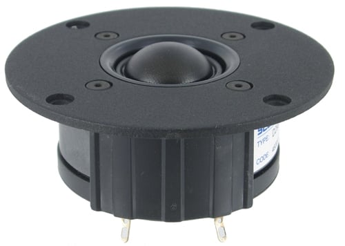
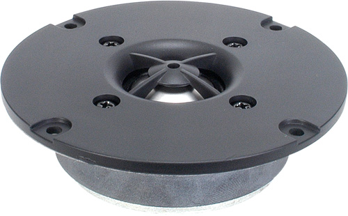
Scan Speak 1” Silk Dome Tweeter with Rear Chamber (left pic); Dayton Audio DC25-T-8 Tweeter (right pic)
|
Tweeter |
Power Handling |
Fs |
Price |
|
Scan Speak 9500 |
150 watts |
500Hz |
$150 |
|
Dayton Audio DC25-T-8 |
50 watts |
1659 Hz |
$17 |
The above example comparing the Scan Speak and Dayton Audio tweeters is to illustrate the benefits a rear chamber have on both lowering resonance frequency and increasing power handling. This is NOT a knock on the Dayton Audio titanium tweeter as its design goals are for a more budget minded system. It does however show you that the type of design executed in the Scan Speak example, typically doesn’t come cheap. You can’t put a pair of $150 tweeters in a bookshelf speaker retailing for $400 but you can and should expect a pair of $3k bookshelf speakers to utilize a tweeter of this caliber.
S ome manufacturers have great success
implementing a shallow horn on the tweeter instead of a conventional flat
faceplate. The advantage in doing so
extends the low frequency output of the driver to better match the directivity
of the midrange. It also means the
tweeter can be rolled off earlier, thus increasing power handling. However, there are no free lunches and the
designer needs to be mindful that doing so does NOT lower the resonance
frequency of the tweeter because the horn typically unloads below the resonant frequency. Thus, care must be taken NOT to lower the crossover
point within the region of the drivers Fs.
Also
another potential drawback of employing a shallow horn is it can reduce the
high frequency dispersion because the tweeter is now "sunken" into a
cave of sorts, so the ultra high frequencies get blocked off-axis. This is why the best designs have a much
shallower cavity than the example shown here.
ome manufacturers have great success
implementing a shallow horn on the tweeter instead of a conventional flat
faceplate. The advantage in doing so
extends the low frequency output of the driver to better match the directivity
of the midrange. It also means the
tweeter can be rolled off earlier, thus increasing power handling. However, there are no free lunches and the
designer needs to be mindful that doing so does NOT lower the resonance
frequency of the tweeter because the horn typically unloads below the resonant frequency. Thus, care must be taken NOT to lower the crossover
point within the region of the drivers Fs.
Also
another potential drawback of employing a shallow horn is it can reduce the
high frequency dispersion because the tweeter is now "sunken" into a
cave of sorts, so the ultra high frequencies get blocked off-axis. This is why the best designs have a much
shallower cavity than the example shown here.
Bottom Line on
Tweeter Resonance Frequency:
The
tweeter resonance frequency is a critical metric in determining where to set a
loudspeaker’s crossover frequency.
Budget minded designs tend to utilize tweeters with a higher Fs and thus
have to rely more on the woofer to handle the critical upper midrange
frequencies. Cost no object systems
typically use more elaborately designed tweeters to lower Fs, increase power
handling and open up more design flexibility options to improve the transition
between the woofer and tweeter for a more seamless blend.
Conclusion
There are always trade-offs in loudspeaker design approaches in all but the very most elaborate and typically most costly designs.
Cast basket drivers enjoy a multitude of advantages over drivers that employ stamped-steel baskets. As we’ve shown, there are advantages in rigidity, precise alignment of the driver’s moving parts, resistance to shipping damage, and even improved aesthetics, for what that’s worth. The biggest disadvantage is the initial tooling expense, which makes it difficult for smaller speaker companies to absorb. But with the large number of independent driver suppliers who offer cast-basket drivers in their lineup, there is really no reason why any speaker company with high-end aspirations can’t use cast basket drivers.
There are many benefits to venting woofers such as reducing mechanical noises and distortion by reducing the air pressure build up at the dustcap and arguably increasing power handling by better managing heat. Venting is essential for bass drivers and beneficial for midrange drivers as well. The downside to a vented pole piece is you have to effectively add more magnet power for the loss caused by the drilled out hole in the backplate. This of course adds cost. Alternatives to rear venting in woofers are punch holes in the former/cone, phase plug physically connected to the pole piece and coupling an aluminum former to an aluminum cone. Affixing an aluminum voice coil to the diaphragm can act as an effective heatsink but it doesn’t address the potential of mechanical noise build up due to too much air turbulence under the dustcap. Employing a phase plug helps to reduce cone mass and on-axis beaming and acts as a heatsink more than it does a vent. However, as a result of the lost cone area, these drivers tend to be at a disadvantage for producing ultra low bass frequencies, hence why they are typically more popular to use as midrange or midbass drivers.
The benefits of exotic diaphragm materials are a slightly less clear-cut situation. There are numerous materials that can deliver excellent performance, and the selection is based more on the specific system goal at hand, rather than an overriding “this is always better” scenario. How the designer deals with the actual damping of the driver to result in a more gentle break up mode (preferably above the crossover frequency) is truly a paramount metric in determining its sound quality.
Lowering the resonance frequency of a tweeter by venting it and coupling it to a rear chamber has many benefits, such as wider midrange dispersion, improved high frequency power handling and smoothing out system frequency response. The penalty of such designs is added cost which cannot be justified in budget speaker systems.
Getting a peek at the guts inside a speaker system you are considering purchasing can tell you a lot about the budget allocated towards the drivers in the design. If the manufacturer doesn’t supply such images, it doesn’t hurt to ask. If not, request a review from us of the speaker system you are interested in as we always dissect the products we review. Manufacturers that truly stand behind the quality of their products love our review approach. Those that don’t, well, they typically don’t submit review samples. Better parts truly can yield better performance in the hands of a competent designer which are more common these days with the advent of inexpensive measurement equipment and knowledge of the basics in loudspeaker mechanics 101.
Acknowledgements
I would like to personally thank the following people for their contributions and/or peer review of this article, all of whom are true experts in their respective fields. Their contributions enabled us to make the most comprehensive and accurate article possible on the very complex topic of loudspeakers cabinets dealt with herein.
- Paul Apollonio, CEO of Procondev, Inc
- Philip Bamberg of Bamberg Audio
- Steve Feinstein, Audio Industry Consultant
- Tim Galdwin, Loudspeaker Driver Engineer for Warkwyn Associates Inc
- Ed Mullen, Directory of Technology & Customer Relations of SV Sound
- Shane Rich, Technical Director of RBH Sound
- Mark Sanfilipo, Audioholics.com Resident Speaker Expert and Writer
- Dr. Floyd Toole, PHD & Chief Science Officer of Harman
Gene manages this organization, establishes relations with manufacturers and keeps Audioholics a well oiled machine. His goal is to educate about home theater and develop more standards in the industry to eliminate consumer confusion clouded by industry snake oil.
View full profile