
The Crossover - Brain of your Loudspeaker System
RBH Sound T30-LSE Crossover
Have you ever wondered how the tweeter and woofer have their responses combined in a speaker system, or what the crossover network is and how it works? If so, this article will shed some light on the least seen and perhaps most undervalued part of the speaker system, the crossover network. Unlike the electronic world where the filters have gone from using tubes, to analog computers to digital signal processors, modern day passive crossovers, a pair of frequency selective filters designed to work together as a single network, are basically the same as they were about 100 years ago when the speaker business was in its infancy. While crossover components and materials and construction have changed, the underlying theory and practice has not.
What does the Crossover Do?
Like your own brain, the crossover network is a director. In addition to its primary function, the passive crossover in practice is expected to do more than simply split the frequency band in two.
1) The crossover allows you to place two 8 ohm speakers in parallel, one for the highs and one for the lows, and still present an 8 ohm, not a 4 ohm load to the amplifier (which is what the amp would see without the network)
2) The crossover allows you to match two drive units of different efficiencies so that the combination of the two does not result in a large shelf in the frequency response.
3) The crossover allows you to equalize the frequency response of either the woofer or tweeter, making the composite response smoother than the unfiltered curves of either driver (woofer or tweeter) would seem to indicate is possible.
Let’s get back to the basic job of the crossover, and see if we can understand how it accomplishes this by learning a few new but simple concepts. The basic job is to send the high frequency information to the tweeter, and eliminate this same band of high frequencies from the woofer. Next, send the low frequency information to the woofer, and eliminate this same band of low frequencies from the tweeter. A crossover is in essence two frequency filter sections working in parallel. A high pass section and a low pass section. These terms are self explanatory. The high pass passes high frequencies, the low pass passes low frequencies. The high pass is placed in series with the tweeter, and the low pass is in series with the woofer. A normal two way crossover will have six terminals. Two in, and four out. Usually the two sections (high-pass and low-pass) are in parallel and both sections ONLY work properly when the woofer and tweeter are both attached and operational. To understand how the crossover does its job, we must first understand the concept of impedance.
The three main passive elements used in all crossovers are resistors, inductors, and capacitors. Impedance is a measure of how much the resistor, capacitor or inductor impedes the flow of electrons at any given frequency. Resistors are the simplest components, and the easiest to understand. The have a constant resistance to the flow of electrons which does not vary with the frequency of the signal. Resistors do not change the phase of the signal, the time relationship between voltage (electrical pressure) and current (flow of electrons). They only consume power and convert it to heat. That is all they do. In a perfect speaker system there is no need for resistors at all. Of course, while there are no perfect speakers, all the basic crossover theory's we use start with that premise.
The second element we shall consider is a capacitor. The capacitor impedes the flow of electrons through it in a way which is NOT independent of frequency. (It would not be technically correct to use the word resistance, but you can certainly think of it as such to conceptualize this). The capacitor has an impedance which is inversely related to frequency. This is to say when you double the frequency of a signal applied to the capacitors terminals, its impedes that electrical flow by half as much as it did at the lower frequency. If you halve the frequency applied, the capacitors impedance (How much it impedes the flow of electrons) is doubled. This is a very useful characteristic which we use to create networks which are frequency selective (like a crossover).
The Maths
The impedance of a capacitor is determined by the equation: Z = 1/j(2piF*C)
Where Z = Impedance magnitude,
J = the square root of (-1) ("Imaginary" component to describe the phase)
pi = 3.1414 etc
C = Value of Capacitance in Farads; 1 Farad = 1,000,000 ufd
I think the first time I read about the square root of (-1) I had an allergic reaction. So, for those of us who are finding it difficult to comprehend phase for the first time, we can pretend it is not there, and to simplify the discussion we will admit to this equation being somewhat incomplete without the “j”, but for the determination of the steady state and not transient value of the impedance, we are OK.
When a capacitor is put in series (shares one electrical terminal) with a resistor, the capacitor acts as a high pass filter. At some frequency it has the same impedance as the resistor, and at a much higher frequency it is like a short, just a piece of wire with little to no resistance (at least in a perfect capacitor). At very low frequencies the impedance of the capacitor becomes so high, that essentially nothing can pass through it. It is this characteristic which is used in endless electronic circuits to allow AC signals to pass through yet completely block DC voltages from one part of the circuit to another.
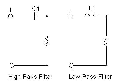
Figure 1
Lets say we have a 10 ufd capacitor and put in in series with an 8 ohm resistor. At some frequency, the capacitors impedance magnitude will be equal to the 8 ohm impedance of the resistor. (Which of course is still 8 ohms at any frequency from DC to daylight.)
Lets do the math.
Z = 8 = 1/{(2)*(3.14)*(F)*(10)*(10-6)}
The capacitor is MICRO Farads, which is millionths of a Farad, so we must multiply the 10 by 0.000001( 10-6) to convert microfarads into Farads, so we can solve for the frequency (F) in Hz. By cross multiplying (multiplying both sides by F and dividing both sides by 8) we get:
F = 1/(2*3.14*8*10*10-6)) = 1990 Hz.
What this tells us is that at 1990 Hz (2 kHz if you are among friends) the impedance of the capacitor is equal to that of the resistor, so at this point the power into the resistor is half what it would be without the capacitor. Put another way, at 1990 Hz, the power into the resistor is 3 db less and this is your crossover point. Above this frequency the attenuation (reduction in power to the resistor) is less, and as we go lower in frequency the capacitors impedance grows larger, while the resistor is unchanged, so the attenuation of signal to the resistor increases. At a frequency of 995 Hz, the attenuation will be 6 db. At 498 Hz, it will be 12 db. We call this a first order or 6 db per octave crossover. That is, in a nutshell, how this works. It grows in complexity when more parts are used, but the basic function is the same. Now if your speaker is a perfectly resistive load, your 10 ufd series capacitor will be a perfect passive 6 db per octave High Pass (HP) filter. Don't worry, life is not that simple.
The other important element used in a crossover network is the Inductor; sometimes called a choke, and sometimes called a coil. They are all refer to the same thing. The Inductor is in many ways the inverse of the capacitor. It too changes impedance with frequency, but in a way entirely opposite to the capacitor. The inductors impedance grows LARGER with increasing frequency, not smaller like the capacitor. Its impedance grows larger at the same rate as the capacitor grows smaller, and the similarity ends there. So if we replace our capacitor with an inductor in the first case we have a first order low pass filter. (As shown in figure # 1)
Note that in higher order networks, second order and above, both inductors and capacitors are used in the same circuit to provide high-pass (HP) or low-pass (LP) filtering. In the HP filter, capacitors are put in series with the load while inductors are put in parallel. (A resistor represents the load in figure 1, and the speakers represent the load in figure 2). In the LP filter the opposite is true, the inductors are in series and the capacitors in parallel with the load (or speaker if you are making a crossover network). Hopefully this makes sense if you keep in mind the direction of the impedance changes of the parts with increasing or decreasing frequency.
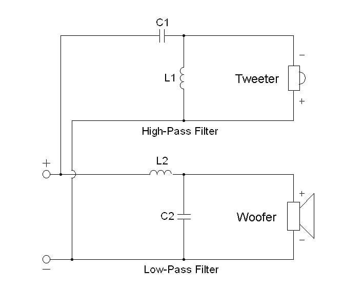
Figure 2
In the network pictured in figure 2, the HP blocking capacitor, C1, increases in impedance with decreasing frequency, while at the same time the shorting inductor L1, decreases in impedance with decreasing frequencies, hence shorting out the low frequencies while the capacitor is increasingly blocking them. The inverse is true of the LP filter. L2 is blocking highs and passes lows, while C2 is shorting out the highs and passing the lows. This is how the LP filter blocks highs and passes lows while the HP filter is performing the inverse function. It is this dual action that allows this kind of network to create twice the blocking action (12 db) per octave of frequency than the simpler 6 db/octave network. If you did not understand this on the first read, that is OK, you have a lot of company. Think about how the capacitor and inductor change their impedance with frequency, and take another look at this circuit diagram. If you try, you can figure out what is going on as the frequencies change.
Back to the simplest network, the 6 db per octave. If I have an 8 ohm resistor, and a 0.001 Henry (1.0 millihenry inductor), at what frequency do I have a 3 db attenuation across my resistor? Let's calculate the frequency where the inductor equals 8 ohms.
The value of the impedance of an inductor is determined by the formula
Z = {(2pi)*(J)*(F)*(L)} where F= Frequency in Hz, L = Inductance in Henries Z= Impedance in Ohm
Like we did for the capacitor, we shall ignore the imaginary "J" term and push ahead.
8 = (2pi)(F)(0.001H) Therefore: F = 8/{(2pi)(0.001) = 1273 Hz
If we want to set the Low Pass frequency equal to the High Pass frequency of 1990 Hz, what inductor do we need? We set F = 1990 and then we can solve for L.
L = 8/{(2pi)(F)} = 6.4 + 10-4 Henries = 0.64 millihenries
We have calculated the parts needed for our first crossover network for our 8
ohm tweeter and 8 ohm woofer with a crossover frequency of 1990 Hz Network below:
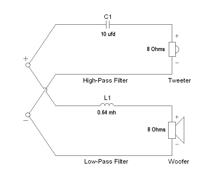
FIGURE 3
Loudspeaker Crossovers cont.
So What’s all the Fuss?
Now the problem with an exercise like this is that the chance that the crossover network will do what you might expect of it is somewhere between slim and none. The main reason for this is that loudspeakers do not have a constant impedance, (like an 8 ohm resistor) nor do they posses flat frequency response through the crossovers region immediately on either side of the crossover point. Let's take a look at a real world example. Let’s say we want to build a system, and we go to a parts vendor and buy a woofer and tweeter we think should work well together. Not being gurus on the subject, we decide to keep it simple and use a simple 6 db per octave network. It is the least complicated, least expensive, and least sensitive to component tolerance, plus it is the only network able to offer (theoretically) perfect transient response characteristics. We will load the driver data from the Xover Pro 3 database and use this program to calculate the crossover parts for a 2000 Hz crossover point as shown below.
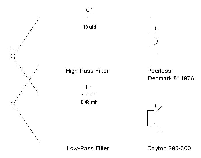
FIGURE 4
Unfortunately there are characteristics inherent in the speakers we use which cause issues with this kind of simple network. Let's take a look at these results from Xover Pro version 3.
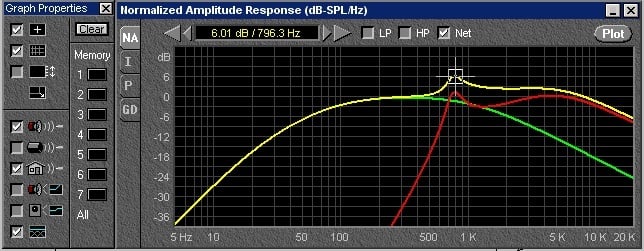
Figure 5 -Peak in tweeter Impedance results in frequency response peak in combined response
This particular tweeter has a resonance at 900 Hz. As we approach the tweeter resonance the Impedance magnitude peaks. The capacitor can do nothing to prevent that, so it does not do a good job of attenuating the signal across the actual speaker the way it would across a simple resistor whose impedance does not change with frequency.
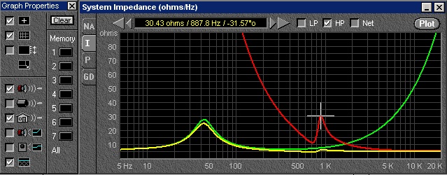
Figure 6 -Impedance of Tweeter and series capacitor (red line) peaks at Tweeter Resonance
If you refer to the original Audio Cyclopedia by Howard Tremaine, it refers to the set of equations widely available in reference texts like the Loudspeaker Cookbook to calculate crossover component values as "constant resistance networks". While a good number of real speakers have relatively flat impedance regions, we rarely cross over those speakers in that region. It is almost always at the extreme upper frequency range of woofers where they have a mostly inductive impedance; or the lower end of tweeters where the HF devices have resonances and therefore impedance peaks as in our example above. In fact many woofers have a voice coil inductance considerably higher than the series inductance required for the first order crossover network. This is why you will often find impedance compensation networks called Zobel networks used in parallel with the woofers.
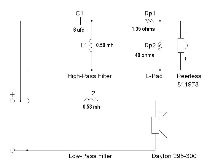
FIGURE 7 - 1ST ORDER LP WITH 2ND ORDER HP FILTER
Since our Dayton woofer is small as is its voice coil, it has a very low self inductance, so in our example we do not need a Zobel network for a good result. On the other hand, our problematic tweeter has to be attenuated a bit to lower its sensitivity to match the woofer, and it also needs a parallel choke to short out that resonant peak so the series capacitor can do its job. This is a second order network and is a bit more complex than a first order. While it brings with it the issues of increased phase shift, more parts and more expense, it also brings with it a greater amount of control over the responses of the speakers in and around the crossover region. By fudging a bit the elements generated by Xover Pro 3, I am able to massage this curve to look very flat.
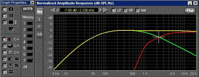
Figure 8 - High Pass, Low Pass and Combination Response using Network shown in figure 7
Now this beautiful curve is not the result of a measurement, but in fact a simple modeling tool which makes a lot of assumptions that may not be true. (Both speakers are in the same horizontal and vertical plane, both are minimum phase, etc.) That said, it sure looks a lot better than what we started with. As you can see by the impedance curve below, there are no sudden jags in the curve, and the impedance of both the HP and LP sections are smooth and quite symmetrical.
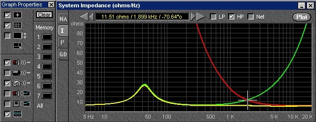
Figure 9 -Woofer, Tweeter and Combination Impedance Magnitudes using Network in Figure 7
Let's take a look at one more example before we finish. We are going to replace our woofer with one having a much more inductive voice coil, arbitrarily chosen to be 1.0 millhenry. In this example, we will use a second order network, and see what kind of change we get from using or not using a Zobel network, an impedance compensation network to make the woofer look non-inductive to the crossover. The Zobel network is the series combination of a resistor and capacitor together in parallel with the woofer. In the schematic below, they are shown as Rz and Cz.
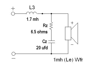
Figure 10 - Woofer with 1st Order LP and Zobel Network
Below is a graph that shows the woofer in three instances. No network. 1.7 mh in series with no network. The same woofer and 1.7 mh and with the Zobel network.
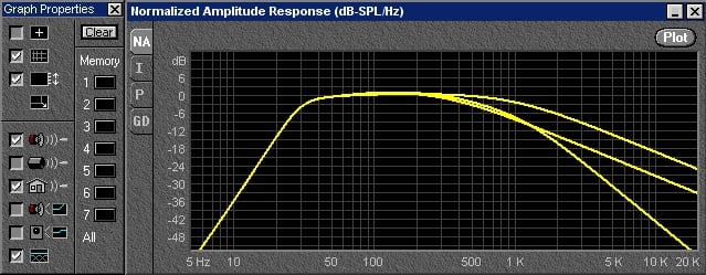
Figure 11 -Woofer raw response - first order LP no Zobel - first order LP with Zobel
The two curves which parallel each other at very high frequencies are the raw woofer (top) and the woofer with the single series inductance (1.7 mh - lower). You will notice that the inductor simply adds about 6 db of attenuation and then offers no more rejection. (This is evidenced by the curves tracking each other at high frequencies). The lowest curve is that of the woofer using both the series inductor and the Zobel network. By returning the apparent impedance of the speaker to that of a simple resistance, the Zobel network allows the series inductor to do its job, that is to offer ever increasing attenuation with increasing frequency. Below is the Impedance magnitude of the speaker with the Zobel Network (flat at high frequencies), the speaker with the series inductor, (highest impedance at 2 kHz) and the speaker with the series inductor and the Zobel network both (middle curve). What this shows is that the inductance of the speaker and the inductor add together to present a very high impedance to the driving amplifier, but not a very effective filter of high frequency information.
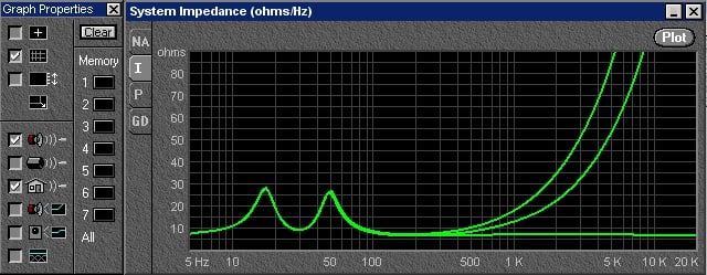
Figure 12 - Impedance
Magnitude of Vented woofer with Zobel (bottom)
Zobel and Choke (middle) and No Zobel network
and choke (quickest to the top)
In practice, very few woofers give us what is called in filter speak, a monotonic decay. This means the response goes away and does not return (as is shown in graph # 7). There are no ripples in that portion of the spectrum we want to deny the speaker, called in filter-speak, the stop-band. This is a really important characteristic of woofers, and very few are well enough behaved in the midrange to not be a problem in this regard. If the woofer has peaks at 3 KHz, and we attempt to cross it over at 2 KHz, you will likely hear the peaks, especially if you are in the woofers direct line of sight. For sure you will see their effects in the combined response through the crossover. As we can see from the above example, making sure the filter can actually attenuate the signal increasingly with increasing separation from the crossover frequency is a very important function with real world speakers, and the Zobel network is an important tool in the arsenal of crossover designers.
So What’s Next?
Now at the outset of this article, I said that we were making certain assumptions about the actual parts we use in crossover networks being theoretically perfect. In the real world, capacitors, inductors and resistors exhibit real world behavior which is neither ideal or perfect. In this part, we considered the importance of real loudspeaker impedance, and how it acts as a monkey wrench to complicate and frustrate the function of constant resistance type crossover networks. In part two of this article, I will discuss non-ideal behavior of real world parts. This I hope, will allow the reader to gain some insight into the kinds of mistakes made in crossovers that can be seen by simply examining the networks, and some flaws which are not quite so obvious. We will also look at a real world example of a crossover I build, and how far it actually deviates from the theoretically predicted network.