
The All Channels Driven (ACD) Amplifier Test
More often than not we see folks on our forums and other forum websites debating how powerful a particular amplifier or receiver is based upon a single test popularized by many print magazines and some online publications called the All Channels Driven (ACD) test. Debates rage on from folks that claim their amp or receiver is better because it delivers more power into ACD or that the manufacturers that produce products that don't deliver their rated power in this test condition are either deceptive or inferior. What consumers fail to realize is almost no multi channel amplifier that is rated beyond 150wpc can meet the ACD specification for continuous power delivery on real world AC power lines. Add to this the fact that program material, be it Movie or Music, never taxes all channels continuously at full power, regardless.
Before continuing on, let's define the conditions of this test which most of the magazines and manufacturers use when making this measurement.
- Power Sweep Test: A single 1kHz sweep of power vs distortion is often used.
- Test at Clipping: This test is usually conducted at amplifier clipping
- Regulated Line: This test is almost always conducted on a regulated line held to 120Vrms via a VARIAC device.
The Power Sweep Test
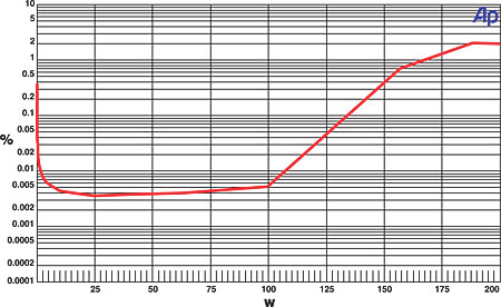
Let's discuss the implications of the power sweep test for a moment. An instantaneous sweep test will NOT yield a true continuous power rating in an amplifier despite the fact that some manufacturers will claim their power ratings are continuous with ACD and some print publications would have you believe it's a continuous measurement. Instead, the sweep will usually run for a couple of hundred milliseconds in a step progression of increased power until hard clipping is evident.
Closer examination of this graph reveals the amp has engaged a limiter or soft clip circuit above 150 watts yet review publications will usually still publish power figures well into the clipping range of the amplifier and make no notation of what is actually happening when the amp is driven beyond its linear range. In addition, most publications will limit the test to 1kHz only, NOT testing for amplifier bandwidth linearity or distortion problems over the full audible bandwidth 20Hz to 20kHz. More on this later.
Test Conducted at Clipping
Most review publications will publish amplifier power measurements into 1% or even 10% distortion. But, is this an accurate test to conduct? We think not. In our extensive testing of amplifiers, we have found most amps will misbehave when pushed beyond 0.1% THD + N. This is easily shown using FFT distortion analysis as shown below.
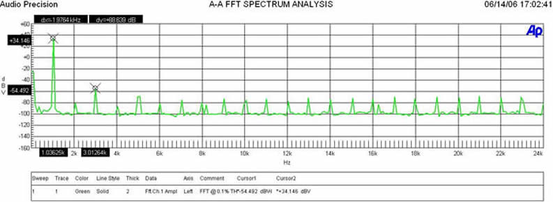
FFT @ .1% THD +N (tested at 1kHz) Power Rating
In actuality I had to conduct this test at 0.07% THD + N power level on this particular amplifier because the harmonics at 0.1% THD were significantly higher in amplitude. (34.146+54.492dBv)dBv = 88.638dBV or 100*log^-1(-88.638/20) = .004% This is a very clean power level as the harmonic distortion profile is well below audible levels.
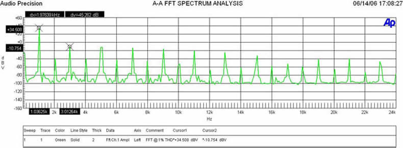
FFT @ 1% THD + N (tested at 1kHz) Power Rating
At the 1% THD power level, the amp enters hard clipping causing nasty harmonic signatures much closer to the fundamental signal. (34.508+10.754dBv)dBv = 45.262dBV or 100*log^-1(-45.262/20) = .550% which is over 100 times the harmonic distortion of our previous distortion measurement.
As you can see in the plots above, the FFT analysis at 0.1% THD power rating is not full of the harmonic nasties seen in the plot tested at 1% THD rated power which is a result of clipping. The resultant power level is lower at 0.1%, but this is a much cleaner and more representative test of the capability of the amplifier.
Distortion Over FrequencyTo understand an amplifiers true power output vs distortion, it should be checked across the entire audible bandwidth and not just one frequency (usually 1kHz). In many cases, an amp will perform ok at 1 kHz but become more stressed at the frequency extremes at full power for a variety of reasons. It is a good measure to run a simple test at 0.1% THD + N @ 1kHz for the amplifier and then apply the same signal amplitude at the frequency extremes (20Hz and 20kHz). You should see similar voltage delivery into our test load and corresponding distortion readings. If the amp is instead driven to 1% THD + N or beyond, at 1kHz, you will likely see the results shown below at the frequency extremes:
|
Test Limit |
20Hz |
1KHz |
20kHz |
|
|
0.1% Test |
0.09% |
0.1% |
0.08% |
THD + N |
|
1% Test |
1.2% |
1% |
1.8% |
THD + N |
The 1% test clearly shows non linear behavior at 20kHz and at 20Hz which would have likely been missed had we only tested at a single frequency. We have definitely exceeded the Linear Operating Region (LOA) of our amplifier in this test condition. But from a numbers stand point, the 1% 1kHz test looks more impressive on paper since we are lead to believe the amp is more powerful. It's also much easier to test an amp into clipping at one frequency which allows reviewers to pump out more reviews in less time. Don't be satisfied with a quick instant gratification power number. You should demand more information about the amplifier's performance.
Regulated Line
The astute audio enthusiast may wonder how it is possible that magazines and manufacturers generate the power measurements from the Device Under Test (DUT) on a standard household 120V, 15A line. Let's do some elementary math to further elaborate.
References:
Household Line: 120V, 15A can deliver max continuous power of (120 x 15) = 1800 watts (assuming no derating as per UL)
Amplifier Efficiency:
Typical Linear (A/B) Amplifier is between 40-50% nominal and up to 70% under full load.
Rail switching amps such as Class G/H can be as high as 70%
Switching amps (Class D) can see up to 90% real world efficiency assuming a properly designed power supply is utilized.
Note: These estimates assume the amp is under full load and that the power supply transformer doesn't overload, operates in the linear VA curve, and maintains regulation.
Let's focus on linear amps for the moment, since these are currently the most popular type tested and purchased by home theater consumer folks.
Now take our 1800 watt max power from the wall and multiply it by our amp efficiency (let's choose 68%) and we get: 1800 x .69= 1242 watts . This is the max power a typical linear A/B amp can deliver on a continuous basis from a 120V, 15A household line - assuming, of course, the amplifier's power supply can consume the entire 1800 watts of power from the line without causing the power transformer to overheat or go into thermal meltdown and likely trip the breaker.
By now folks from the ACD camp are saying, - well let's use a 20A line instead! That only gets the designer 4 more amps - or 2.6A with a normal power amp! What they fail to realize is most UL compliant consumer electrical devices utilizing the IEC320 receptacle, limit the max current consumption to less than 15A to prevent arcing which can cause a fire, death or serious injury (not to mention voiding your liability insurance). Unless the amp has a specialized connector on the back, or two independent power cords, it is likely it will be limited to 15A continuous consumption for safety's sake. We shall consider those type of devices as an outlier (not typical) and continue on with the more typical consumer devices reviewed and purchased for our home theater systems.
As a side note, other limitations include the AC wall outlet and breaker in the fuse box as well as the potential for 14GA wire run to the AC socket - 12GA wire has to be used for a legitimate 20A breaker.
As we already established, our linear amp best case continuous power delivery is limited to around 1242 watts from a 15A line.
What does this give us under the ACD test?
5 Channels Driven: 810 / 5 = 248 watts per channel
7 Channels Driven: 810 / 7 = 177 watts per channel
Note: This doesn't factor in any additional losses due to processing, and other active devices in a receiver.
So how is it possible that the manufacturers and/or publication reviewers can generate higher #'s than this? The answer is three fold.
- They regulate the line voltage using a VARIAC to ensure it maintains 120V under full load.
- They negate the fuse rating of the amplifier. Some publications will actually remove the rail fuses and replace them with a short for this test.
- Their tests are instantaneous (NOT CONTINUOUS) power sweep measurements into hard clipping at a single frequency, usually 1kHz.
This doesn't sound like a typical scenario (or a safe one at that) in a consumer environment. It also doesn't sound very realistic, does it?
The All Channels Driven (ACD) Amplifier Test - page 2
Power Limitations of Power Receptacles & Consumer Devices
An Interview with Michael Schenck of APC AV
When I asked our friends at APC AV (one of the leading authorities on power, filtering and surge suppression in the PC and AV marketplace) to elaborate about the standard IEC connector on the back of most receiver/amplifiers being limited to 15A, here is what they had to say.
APC AV: The standard IEC connector (as used in the US) is approved for use on products 12A of CONTINUOUS LOAD. Please note that the connector itself is rated for 15A, but the products are rated for 12A. The connector is limited to this amount mostly for heating and arcing. The mating surface limits the amount of current. The spacing between conductors and the hood limit the possibility of arcing,
If products are designed to be UL (or NRTL) approved, the products must not draw more than 80% of the branch circuit's current rating. This stems from a National Electric Code requirement that states a loads may not continuously draw more than 80% of the rated breaker (with some exceptions) to provide a margin of safety and headroom. The 'standard IEC connector' is commonly called a '15A - connector' because it is intended for use on 15A branch rated circuits. The '15A' IEC connector is typically coupled with a NEMA 5-15P, also a '15A plug'. In practice though, the connector should not be used with products greater than 12A.
IEC 13 & 14 are the most common IEC connectors used in consumer AV gear. There are notable examples where some power conditioners manufacturers' equip their products with mixed amperage receptacles. In other words, a '15A' IEC 13/14 inlet style power cord is used on a product with '20A' NEMA 5-20 receptacles. This allows the user to plug a '20A' load into a '15A' circuit. It is OK to use a '15A' plug on a '20A' branch circuit, but not a '20A' receptacle on a '15A' branch circuit. I guess somehow they think providing a '20A' IEC or NEMA receptacle with a '15A' plug gives them more power. In reality, it creates a dangerous overload condition. But that is a conversation for another myth destroying article!
Power strips, surge protectors, and Relocatable Power Taps (RPT) are one expectation to the 80% derating rule - they are simply meant to be an extension of the wall. An RPT is rated for 15A - but it must not consume significant power on its own. Some irresponsible manufacturers will classify power hungry power conditioners as RPTs, exploiting a loophole in the system.
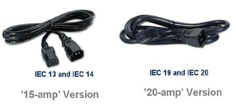
Note: IEC 13 & 14 are the most commonly used in consumer AV gear
Companies can circumvent the power draw derating requirements of the Standards during 'non-standard' or 'non-continuous' use. Voltage regulators by their nature will operate with increased current during non-standard conditions. APC automatic voltage regulator units will provide 120V @ 12A OUTPUT. This means, we will have to draw more input current at 110V in order to sustain the user's load. At 120V, we cannot pull more than 'rated current' - 12A - from the wall continuously. However, our peak current draw can exceed this by a few amps for short periods of time under transient usage.
Can you confirm and provide a standard that references this?
APC AV: The National Electric Code (NEC) is very clear: Article 110 plainly states any product connected to the electrical supply in the U.S. must have a National Recognized Testing Laboratory (NRTL) safety agency Listing mark, or be specially approved by an onsite electrical inspector. For the most part, Underwriters Laboratories (UL) and other NRTLs follow NEC guidelines. Article 210 specifies the 20% derating factor - as specified in a table from the 2002 NFPA NEC Handbook.
Table 210.21(B)(2)
Maximum Cord-and Plug- Connected Load to Receptacle
|
Circuit Rating (Amps) |
Receptacle Rating (Amps) |
Maximum Load (Amps) |
|
15 or 20 |
15 |
12 |
|
20 |
20 |
16 |
|
30 |
30 |
24 |
The NEC also states that branch circuits are sized according to the VA (Volts x Amp) requirement of the loads. It is NOT correct to assume Watts = VA. It is very possible a 1575W load will need 20A of current, necessitating a 30A branch rated circuit.
According to Crown Audio: "The amperage capacity of the power cord is determined by the amount of current drawn by the amplifier from the AC mains when measured according to CSA/CAN E60065, IEC60065 and UL 6500 standards, which all relate to audio/video and musical instrument apparatus for household, commercial, and similar general use."
Refer to: http://www.crownaudio.com/pdf/amps/137331.pdf
The All Channels Driven (ACD) Amplifier Test - page 3
So how could some amp companies circumvent this? We have seen a 7CH linear amp tested in a magazine where they claimed it generated more than 315wpc x 7 ACD, which implies a sustained output of more 2200W requiring more than 40Amps through a single power cord!
APC AV: Circumventing the Rules…
It is ok for product to slightly exceed the branch rating for non-continuous and abnormal circumstances for brief periods. Nonetheless, there are many products in the AV market that lack any sort of NRTL mark - high end, expensive, and well known products lack UL, CSA, VDE, etc approval. Obtaining a NRTL mark does not guarantee performance nor absolute safety. It certifies the manufacturer took the time to design a product to meet commonly accepted standards for safety and regulatory practices.
There are many products that lack a Listing mark altogether or may use terminology like 'Adheres to', 'Designed to', or 'Meets standard'. I'm not sure why they chose to break the law (in some states & localities) and offer a product without a Listing mark. Perhaps their products cannot meet the standards or the company is too small pay for the testing. It is scary to think that if my house burned down and a non-Listed product caused it, the insurance company may not honor the claim. Further, I may be held liable for damages and injuries by using a non-NRTL approved product. The dealer, installer, distributor, and manufacturer will certainly be held liable/negligent for so grossly ignoring code & regulatory requirements.
APC AV: 315wpc x 7 ACD….
Watts are Watts are Watts. Conservation of Power applies to all things electrical - If the amp is supplying 2200W to the speakers, 2200W must be supplied to the amp. Neglecting efficiency calculations, power supplies, etc, an amplifier supplying 2200W continuously will require 18.3A @ 120V - it will blow a 15A breaker...no bones about it.
Let's put this into some context with some definitions of power:
Volt-Amps (VA) - the apparent power is the product of the voltage being supplied to the equipment and the actual current being drawn by the equipment. VA determines the wire and circuit breaker size. The wire and circuit breaker determine the branch circuit rating.
Volts x Amps = Volt-Amps (VA)
Power Factor (PF) - determined by the phase angles between the current and the voltage. It is expressed by a percentage. It does not have any units and defines the relationship of VA to Watts.
Power Factor = Watts ÷ VA
Power Factor = VA cos α
Watts (W) - the actual power drawn by equipment and it determines the power purchased from the utility company. Also known as REAL power, watts do the actual WORK in electronics, motors, light bulbs, etc.
Watts = Power Factor * VA
Editorial Note about Power Factor from APC AV
Most consumer amplifiers utilize large transformer followed by a full wave bridge rectifier and bulk supply capacitors. The current drawn is out of phase with the voltage - the Power Factor (PF) will be less than 1. This is called a non-Power Factor Corrected (PFC) power supply. A PFC power supply has a PF that is nearly 1.
The PF for most consumer amplifiers is 0.65 - 0.72. This means only 65%-72% of the available branch rated current can be turned into REAL power. The larger the amplifier, the worse the PF issue becomes. A light bulb however, does not have any reactive components - nothing changes the phase angle between the current and voltage. It is a called a resistive or linear load. It's PF=1. A light bulb that consumes 1A @120V is a 120W light bulb. (120W = 1A x 120V x 1).
Some consumer amplifiers and most high power professional audio amplifiers use switching power supplies to power the amplifiers. These switching powers supplies may or may NOT employ PFC.
Engineers and power minded readers will note that the AC line feeding your power amplifier will distort and may increase the power factor. The slight increase in power factor will not yield enough of a corresponding increase in REAL power to over come a low PF.
Following the NEC & UL requirements:
Volts x Amps = VA
120V x 12A = 1440VA
Volts x Amps x PF = Watts
12A x 120V x 0.65 = 936W
12A x 120V x 0.72 = 1036W
A non-PFC transformer based amplifier can only draw approximately 1000W of usable power. Ignoring the NEC & UL (consuming 15A), that number increases to approximately 1200W.
Using your 315Wx7wpc channel example, let's look at the actual AC line current consumption (ignoring power supply and amplifier efficiencies):
2200W ÷ (0.65 x 120V) = 28A
2200W ÷ (0.72 x 120V) = 25.5A
Clearly 25-28A grossly overloads a standard '15A or even '20A' line cord and branch rated circuit.. The amplifier would need to be outfitted with a 35A or larger AC connection. Might I suggest a 120V dryer-style plug?
Is it accurate to determine an amplifier's true power rating by only knowing the VA rating of the transformer? Or can this be fudged if the transformer isn't being rated in the linear portion of the VA curve?
APC AV: The straight and easy answer to your question is 'No'. It is not possible to determine an amplifier's true rating by only knowing the VA of the transformer. It may give you a rough approximation, but nothing more.
A transformer's rating is a moving target that encompasses regulation, thermal, frequency, duty cycle, and load information. For example, different regulation specifications are typically provided for different load points. The regulation specification tells the designer what to expect when the transformer is 'fully loaded' given a certain load current wave shape. The load current wave shape will vary depending upon the application - most transformers are specified with sinusoidal current draws.
A step-down transformer whose secondary (output) may supply 59VAC unloaded. This will drop to 55VAC when loaded with a sinusoidal current draw (resistive load). An amplifier power supply will have a completely different load current wave shape and the loaded voltage may be significantly less.
The secondary (output) voltage will always decrease with an increase in load. However, the application, design, and COST determine the amount of voltage drop. Transformers can be designed such that the secondary voltage varies little with load. This is called the 'regulation percentage' or percent regulation. A good transformer should have 3% or less regulation percent. Transformers that have approximately 5% or more are considered 'loose' and have poor regulation.
Regulation Percent = (V no load - V full load) ÷ (V no load)
For example, a theoretical 100W, 4ohm amplifier requires 30V at full power. The output current is 7.05A. Size, weigh and cost are limiting the transformer size, so the designer decides to squeeze as much out of a transformer as possible.
Regulation Percent = (35V - 30V) ÷ (35v) = 14.2%
An amplifier's power supply transformer that drops by 14% under full load implies the transformer is loose. Note: Some call this specification the 'percent regulation' and will specify it as follows:
Percent Regulation= 1 - (V no load - V full load) ÷ (V no load)
Percent Regulation = 1 - (35V - 30V) ÷ (35v) = 85.8%
Like all things electrical, the relationship between the thermal and electrical designs must be fully understood. This relationship will determine the peak vs. continuous current rating of entire system. Transformers will have similar ratings - one transformer may have lots of thermal mass and be able to withstand full load indefinitely with excess capacity for peak loads. Another transformer may heat up very quickly a during the same loading and have no margin for peak loads. Things like heat generated from copper losses (I^2*R), core losses, primary/secondary voltage, number of taps, current, loading, and load wave shape all affect a transformer's rating.
Inexpensive low frequency transformers limited by cost will have less core material and smaller gauge copper windings. For the same load, smaller gauge windings will generate more heat than large gauge windings. The amount and type of core material will also vary with cost. However, transformers, if designed properly, can transfer power at efficiency levels exceeding 98% (or more!) such that the secondary voltage varies little with load.
The transformer is only one part of the amplifier power supply. The amount of bulk capacitance will determine the amount of ripple on the power supply rails. Bypass capacitors and EMI filtration will determine noise immunity. Some amplifiers have regulated power supplies which add a level of complexity and cost.
It is important to understand not one electrical or mechanical component will provide a definitive rating for any electrical device, let alone an audio amplifier.
The All Channels Driven (ACD) Amplifier Test - page 4
An Overview of Power Supply Basics
Editorial Note on Transformer Basics from APC AV
The most basic transformer is comprised of two wires lying next to each other. Applying a voltage to one of the wires - the primary wire will create a magnetic field. Altering the voltage changes the magnetic field. This magnetic changing field induces a voltage into the secondary wire. Increasing the primary wire's exposure to the secondary increases the efficiency of the induced voltage. Wrapping both wires in a coil increases this exposure. Adding a magnetic material, like iron, will concentrate the field and increase the efficiency even more. Connect a load to the secondary wire and the field will transfer power. The field within the magnetic material (the core) is called flux. The amount of flux in the core is called flux density. The voltage present on each turn is called Volts Per Turn. Different windings can be added and power can be transferred to different loads at various voltages. (The amplifier rail might require 35V, but the logic supply requires 5V. A second transformer is not necessary - just a winding).Transformers become hot because of two factors: the current flowing through the wires (I^2*R) and core losses. Every time flux is induced the core, the material heats up slightly, just like current through a wire. Changing the flux creates eddy (stray, non-productive) currents that do nothing but generate heat. Core material and geometry can minimize eddy currents and core losses. This means most transformers will consume a few watts just be being connected to the wall. Inexpensive transformers use higher loss core material that generates more heat. Selecting larger diameter wire for the turns, lower loss core material, and improved core geometry will lessen the amount of power wasted.
Editorial Note about low frequency AC power supply transformer saturation from APC AV
The term transformer saturation is thrown around too lightly. Transformers typically saturate under a few conditions: over-voltage, too low a frequency, and too light/not loaded. Transformers with too small or under designed cores will saturate when the flux density is too high. Flux is created by the voltage on each individual winding (wire wound around the core) or the Volts-Per-Turn. The amount of flux in the core is called the flux density.
The core typically made of laminated steel or iron is capable of withstanding a specified flux density, and if the flux density it too high, the core becomes overloaded. The magnetic field will collapse and the transformer will act like a partial short circuit. The current will begin to increase exponentially. The transformer core must also 'reset' within a given time period otherwise the flux density will continue to climb and the magnetic field will collapse. This is why DC is never used with low frequency AC transformers.
If the input voltage is too high, the volts-per-turn will be too high. Therefore the flux density will be too high and the core will eventually saturate. If the core is not allowed to reset within a given time period (using a 60Hz transformer on a 50Hz grid), the transformer will also saturate.
Theoretically, a transformer can saturate while under heavy loads, but this is not likely. Increasing the load, increases current and the Volts-Per-Turn will begin to drop. The losses (resistive) and the magnetizing current (current used to magnetize the core) will begin to dominate. The flux added by the primary is 'drained' by the secondary and it would be difficult to saturate a transformer with too high a load.
In summary the type of core material and winding gauge affect the transformer's performance at any load. A transformer without enough core material can saturate readily. A simple experiment will demonstrate transformer saturation. Increase the input (primary) voltage on an unloaded/lightly loaded inexpensive 60Hz transformer. Observe the input current on an oscilloscope with a current probe. The large current peaks is the magnetizing current gone awry - the core has saturated because there too much flux in the core. Transformer cores saturate when the flux density becomes too high - flux density is determined by voltage, loading, and frequency.
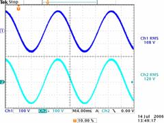
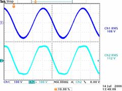
APC AV: A great example of a weak transformer - or one that has poor regulation - is a smaller variac similar to those used to evaluate amplifiers. In this example, the variac was setup to boost the output voltage from 108V to 120V. In an unloaded state, the Variac was boosting the voltage by 12V RMS. The variac began to lose regulation as the load was increased to 50% of its rated load. This particular test was only run at 50%, imagine how much worse it will be at 100%!
V no load RMS : 120V
V 1/2 load RMS: 112V
½ Load Percent Regulation: 7%
The clipped waveform also changes the behavior of the power supply. The peak voltage available for the bridge rectifier has been reduced from 170V to 158V - a whopping 12V drop in the peak voltage output. (120*SQRT(2)=170V)
|
Variac is unloaded. Ch1: Input Voltage Ch2: Output Voltage
|
Variac is 50% loaded Ch1: Input Voltage Ch2: Output Voltage
|
The following example is based upon a commercially available stereo audio amplifier. The power ratings were taken from the manual.
100W RMS into 8 Ohms
150W RMS into 4 Ohms
Using only basic power equations, I back calculated the required amplifier output voltage and current to satisfy the loads.
100W @ 8 Ohms - > 28.3VAC RMS, 3.54A
150W @ 4Ohms - > 24.5VAC RMS, 6.13A
These numbers indicate the transformer and power supply are pretty weak - the power supply voltage rails sag sufficiently enough to prevent the power from doubling with half the resistance. If the power supply transformer had sufficient regulation and the rest of the amplifier was designed for it, the output power should look like this:
100W @ 8ohms - > 28.3VAC RMS, 3.5 Amps
200W @ 4ohms - > 28.3VAC RMS, 7.05 Amps
Recall that Power =( V^2 ) ÷ R, P = V x I
A properly designed power supply is going to limit itself to prevent damage to itself and to the load. So any good power supply should prevent excessive current and voltage. Too much current can over heat components. Too much voltage can cause capacitors to vent and components to explode!
APC AV Additional Comments on Amplifier Ratings
APC AV: Consumer amplifiers are rarely if ever called on to produce continuous power - far from it. The duty cycle (ratio of on-time to off-time) is much less than 100%. Different types of audio have different duty cycles and will load the amplifier differently.
Take a look at the chart below from Crown Audio. These numbers are common throughout the professional audio world. Numbers similar to this can be found in the SAMS Professional Sound Engineering Handbook as well.
See: http://www.crownaudio.com/pdf/amps/138350.pdf
Duty Cycle for different program materials:
|
Speech |
10% |
|
Acoustic/Chamber Music |
20% |
|
Full-Range Rock Music |
30% |
|
Compressed Rock Music |
40% |
|
Pink Noise |
50% |
As illustrated above, an amplifier's duty cycle is quite low. So your 315W x 7 channel amplifier may have a worst case duty cycle of 30-40%. With that in mind, let's re-evaluate the amplifier example (neglecting efficiency, power supply design, amplifier topology, etc):
# Channels x Watts Per Channel x Duty Cycle = AC Power
315W x 7ch x 30% = 660W
315W x 7ch x 40% = 882W
Max Average Power Draw
(660 W + 882W) ÷ 2 = 771 W
Max Average Power Draw ÷ (PF x Voltage) = Current Draw
771W ÷ (0.65 x 120V) = 9.88A
So your theoretically, your 7-channel behemoth could be supplied by AC power from a 15A branch rated circuit. However, that is theoretical and not reality. Factor in the amplifier efficiency of 35-60% (topology dependent) and power supply efficiencies of 60-85% and suddenly the amplifier powered by a cord mandated 15A branch circuit may not be sufficient. (Packaging a consumer device with a NEMA 5-15P limits the device to 12A continuous draw which is all a 15A branch circuit should provide to a single load).
An unregulated power supply (transformer, bridge rectifier, and capacitor) can be quite efficient -upwards of 85%. The bridge rectifier losses will scale linearly while the transformer may not. Moderate to high quality capacitors will add little to the overall power loss. Traditional regulated power supplies using linear regulators are horribly inefficient. The quality of the transformer and regulation scheme can easily reduce efficiencies to 60%.
Assuming the best case scenarios for traditional amplifier and power supply design:
System Efficiency = Power Supply Efficiency x Amplifier Efficiency - % Ancillary Loads
System Efficiency = 85% x 60% - 2%
System Efficiency = 49%
Continuous Power Draw = Max Average Power Draw ÷ System Efficiency
Continuous Power Draw
771W ÷ 49% = 1573 W
Continuous AC Power ÷ (PF x Voltage) = Current Draw
1573W ÷ (0.65 x 120) = 20.1A
As explained above, 20.1A, 1573W, 2412VA is too much for a 15A branch circuit limited to 1440VA (12A x 120V). It is too much for a 20A (1920VA) branch circuit! A 30A (2880VA) circuit must be used for this scenario to be correct.
Music has a very high peak to average ratio - otherwise known as crest factor (CF). This CF will ultimately determine the electrical rating of an amplifier. If an amplifier is expected to deliver 90dB @ 1m of sound from a 86dB/1watt speaker, the amplifier will need to produce approximately 3.5W of continuous power. But 3.5W of 1KHz tones isn't pleasant to listen too. A Symphony will have a tremendous loudness range from whisper quiet to shouting/subway platform levels. The peaks will be much higher. That same 86dB speaker would need to produce 60dB (~0.05W) all the way to 100dB (~30W) at your listening position. Those 30W amplifier peaks will be short lest you damage your hearing. Kick drums, movie explosions may drive this number higher, but the other factors being to surface such as speaker abnormalities, room acoustics, and human ear sensitivities name a few.
The bulk capacitance within the amplifier should be more than capable for supplying peak musical demands in consumer audio applications. Thermally, I should hope the power supply and amplifier would be capable of handling 30-50% of its rated RMS output. Electrically, I should hope power supply would be capable of supporting the thermal limits as well as be capable of handling 2-3 times rated RMS output for short periods (kick drum, movie explosions, T-Rex, etc).
The maximum power that can be extracted from the wall is limited by the power factor of the amplifier. Modern sound reinforcement amplifiers have PFC front ends - they draw a PF approaching 1. Therefore, they can extract the maximum power from the wall - all of the power used is REAL power, not Reactive or Apparent VA power. While most consumer amplifiers may ELECTRICALLY be able to sustain rated power output (on a channel by channel basis) for a few moments, THERMALLY they cannot.
The peak power demands are satisfied by internal energy storage (big caps). For the rest of the time, the amplifiers only produce a few watts RMS. An astute observer will have realized long ago a simply fact: if your 315wpc x 7ch amplifier can function well off of a 15A branch rated circuit, it must not be doing much WORK.
Watts are Watts and energy does not appear out of thin air. IF it is coming out the amp, it has to be coming out of the wall and then some.
The All Channels Driven (ACD) Amplifier Test - page 5
Common Questions about Amplifier Power
Now that we've digested that enlightening Q & A informational with APC AV about power ratings, lets get back to answering some common questions that have plagued the minds of many Audioholics visiting our forums and reading magazine review data and manufacturer literature.
![[sunfire]](../../../images/sunfire.jpg) How can my amp claim 200wpc / 400wpc x 7 into 8/4 ohms, respectively, ACD?
How can my amp claim 200wpc / 400wpc x 7 into 8/4 ohms, respectively, ACD?
Any amp can claim anything… but as for actual delivery - it can't. Unless, that is, it has two individual and independent power cords feeding multiple power supplies. In order to achieve 200wpc x 7 continuously with all channels driven, it would require a whopping 3111 watts, or two 120V dedicated lines consuming almost 13 amps each!
An amplifier claiming 400wpc x 7 into 4 ohms, all channels driven, would require over 6200 watts! That's 3 ½ dedicated 15A lines running at full power - or, perhaps, a mini self contained nuclear reactor in your home! Remember Three Mile Island ? Those guys liked their music LOUD!
Is the ACD Test Representative of Real Music and Movie Program Material?
To answer this question, we have called upon our friends at THX, (namely Senior Fellow John Dahl), who have, to this date, done the most extensive and practical multi-channel real world testing of which we know.
THX: We have a 5.1 logging computer that we have used to play and profile a vast variety of movie, music and game material, identifying how much power is needed in each channel, at what frequencies, and for how long. This is the only way we know that makes it possible to develop a spec and test that guarantee that the product will play any commercial program material at reference level.
The test itself uses programmed bursts of energy that mimic the maximum duration peaks that a product must play. We assume a minimum impedance of 3.2 ohms with low reactance. The test is automated and tests channels singly and in groups with high level burst signals at various frequencies, groups of frequencies, for varying lengths of time.
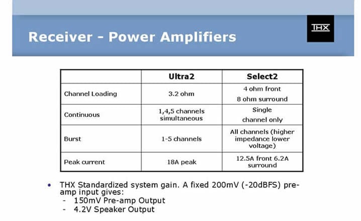
A THX amp will play any commercial program material to reference level when hooked to an 89dB sensitivity speaker with a minimum impedance of 3.2 ohms. Here are a couple of charts summarizing the numbers for Ultra2 and Select2:
THX employs a proprietary Burst testing scheme - NOT a continuous single tone ACD test at full rated power. They do, however, check to see if the product will swing the required voltage to meet THX guidelines with a given load on 1, 2 or 5 channels driven only long enough to look at the waveform on a scope. Usually that's a few seconds, which is plenty long enough to ensure it will perform similarly on program material. If they see problems on the 1kHz waveform, they check further with higher and lower frequencies.
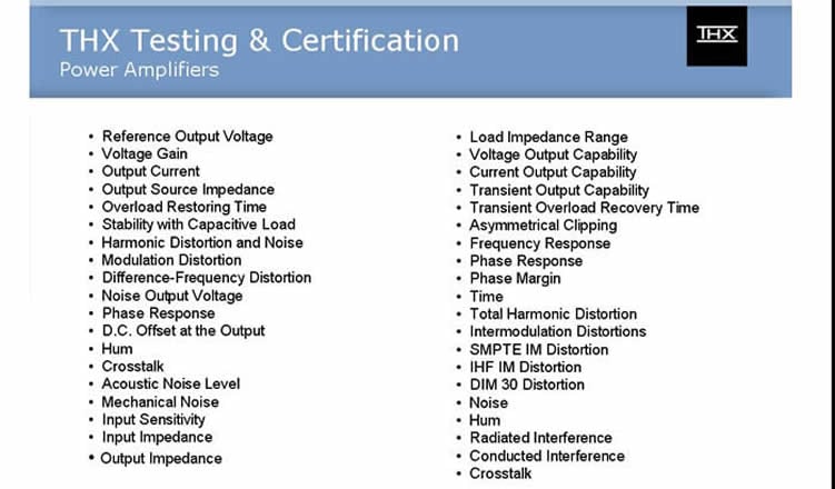
This is a comprehensive list of other parameters and metrics THX uses to certify amplifiers.
For more input on the ACD Test relevancy, we quote Michael Schenck - Power Electronics Design Engineer of APC AV.
APC AV: I don't agree with testing All Channels Driven - it is not a realistic measure of anything useful. There is no standard means of testing with no valid data to support its veracity. I've never seen any data that says an ACD test is similar to the power consumed by a kick drum or T-Rex. I feel it is important that an amp be capable of driving all the channels at 1/3 or 1/X power concurrently and continuously without overheating or blowing up.
Common sense requires that an amplifier be electrically capable of supplying enough power to satisfy musical and theatrical dynamics without clipping. Therefore, a peak rating with a foundation in reality is also important, I want to know the amp is capable of supplying continuous and peak power to the speakers when needed.
So the ACD is entirely invalid?
The answer to this question is a qualified "It depends." ACD can be thought of as a conditionally valid test to determine if an amplifier is capable of instantaneously consuming all of the power from the wall outlet. In the best case scenario, it can reveal the absolute capability of the amplifier's power supply. If the amp has a robust power supply then you will simply be testing for line voltage sag on an unregulated line up to the fuse limit of the amplifier.
The problem however (as documented in our previous article: The All Channels Driven Test Controversy) is that many budget products are designed for real world performance and must make trade offs for safety and heat dissipation reasons. As a result, they design their amps to be dynamic, but limit the total output capability of the product with a limiter that activates if more than three channels are driven at full power. The result of driving more than three channels at full power is reduced power delivery to all channels to satisfy the heat dissipation requirements of UL, as well as the manufacturer's requirements for dependability and reliability. Thus, when a publication does the classic ACD test into 5 or 7 channels, the reader can get the wrong impression that the amplifier isn't very capable at delivering power despite the fact it exceeds manufacturers specs with flying colors with only one or two channels driven continuously, and also satisfies the old FTC mandate for rating power into two channels.
Let's take the following Scenario when comparing two similarly priced receivers.
- Receiver #1: rated at 110wpc (# of channels driven not specified, but FTC mandates it must apply to at least two channels)
- Receiver #2: rated at 70wpc ACD
If we bench test both receivers with just two channels driven, we more often than not find that Receiver #1 was able to comfortably exceed its rating into 8 ohms and deliver respectable power delivery into 4 ohms (usually higher than the 8 ohm rating). Receiver #2 will usually exceed its 8 ohm rating but typically at a smaller margin than receiver #1 and, more often than not, maintains a similar power rating for 8 and 4 ohm loads. Of course an ideal amplifier should act like a constant voltage source and double power delivery when speaker impedance is halved. Very few receivers, and only the better separates amps, have a robust enough amp topologies and correspondingly robust power supplies to achieve such a feat.
So, in reality, Receiver #1 has the potential to deliver more power than Receiver #2, especially into 4 ohm loads, when driving one or up to three channels simultaneously with a correlated audio source. But because of the thermal limitations of the budget sized receiver, which aims at designing a dynamic amplifier over one that can provide sustained power into all channels simultaneously, it has to limit the power delivery when the amplifier is taxed with a correlated audio source to more than three channels. During loud transients Receiver #1 will likely be able to deliver cleaner output because it has more available headroom than Receiver #2.
On the other hand, the ACD test can very easily boast over inflated power figures for amplifiers that don't employ this form of current limiting. This is true in particular when the audio publications test in the 3 conditions we previously mentioned - instantaneous 1kHz power vs THD test, VARIAC regulated line, and bypassing the internal amplifier fuses. Thus, the consumer is misled into believing the inflated power measurements are continuous and achievable in typical household installations.
Since this test isn't representative of music or movie program material, and it is usually conducted in conditions not representative of normal product usage, its validity is questionable at best. It is certainly not a clear delineation of true amplifier performance in a real world environment.
So Why Do We Need Big Amplifiers?
Despite the fact that few boat-sized multi-channel amplifiers can deliver their inflated 200-400wpc into all channels simultaneously, there is still validity for these amps. An amp with a huge power supply and multiple output devices per channel can typically drive a wider range of speaker loads and usually has vanishingly low output impedance, making it less susceptible to frequency response variations when driving a reactive load such as a loudspeaker. It also has the ability to act more like an ideal voltage source by doubling its power with halving load impedance. This allows the amplifier to deliver more steady state power to low impedance loudspeakers.
Editorial Note about Amplifier Output Impedance
Output impedance is determined by output stage topology and feedback ratio. The internal wiring often (especially if there is internal speaker switching) has more impedance than the amp as does the output choke which is connected after the feedback stage. The ability for an amp to double power with halving impedance is almost all power supply influenced assuming the amplifier output stages can sink the required current to sustain the power levels.According to Bruno Putzeys of Hypex, it turns out that the output choke is usually the dominant factor in determining amplifier output impedance, because it's outside the loop. Before the output choke, any reasonably designed amp has negligible output impedance. In addition, boat-sized amplifiers typically have such powerful (and hence slow) output stages that loop gain needs to be scaled back a bit, increasing HF distortion. Funnily enough, it is precisely HF distortion that fools the human ear into thinking the bass is tightly controlled.
So What Have We Learned?
- Most of the ACD power figured in magazines and/or in manufacturers product literature are highly conditional, vary from publication to publication, and are usually not product representative. These ratings are typically taken using the 1kHz Psweep test for 8 ohms at amplifier clipping and almost never done at 4 ohms for all channels.
- The ACD test is NOT representative of normal program material.
- Compromises in budget gear must be incorporated to produce dynamic amps while meeting stringent UL/CSA heat dissipation requirements under continuous loading conditions.
- Despite many manufacturers' boasts to the contrary, most multi-channel amplifiers' ACD power ratings are, at best, a highly conditional rating.
- The ACD test isn't a clear indication of the power capabilities of an amplifier designed for dynamic power delivery as a primary metric.
If ACD Doesn't Matter, Then What Does?
The following metrics can provide a far more insightful view of real world amplifier performance:
- Amplifier Bandwidth Linearity
- Output Impedance
- Amplifier Distortion + Noise at Various Power Levels
- Signal to Noise Ratio
- Channel to Channel Isolation
- Amplifier Stability under reactive load testing
- True continuous undistorted power delivery into one or two channels under various loading conditions
- Amplifier power stability with multiple channels driven at reduced power while the primary one or two channels are driven at full rated power.
These are just some of the primary metrics of concern when dealing with true amplifier performance.
A lot can be determined about an amplifier's performance by testing the above criteria with just 1 or 2 channels driven, while a comparison is made with the other channels at idle vs. being driven at a continuous reduced power level. Since the typical program materials we deal with are dynamic in nature, it's important for an amplifier to be able to reproduce large transients. Doing so requires careful design in the amplifier's power supply and output stages.
To test the amplifier's ability of handling multi-channel program material, a tone burst method such as the test THX implements is more practical and accurate in gauging amplifier performance. A slightly modified approach to the new IEC ruling for multi-channel amps is another viable approach (article coming soon).
So, Who is to Blame For Inflated Power Figures?
- First, the consuming public for demanding unqualified numbers over real performance.
- Second, the review publications for pandering to an uneducated demand for numbers without attempting to frame these "test results" in "real world" performance terms.
- Finally, the manufacturers themselves for playing the numbers game despite the fact that they should know better.
Closing Thoughts
Understanding amplifier power ratings can be a difficult task in an industry almost devoid of standards and rife with loose interpretations of existing standards that have exceeded their usefulness and practicality in today's multi-channel environment. Deceptive marketing and inadequately stated test conditions certainly don't help this situation.
So What are We Doing About This?
Audioholics is working closely with industry experts and leaders to formulate a new amplifier measurement standard that is both practical and executable. We are hopeful that our pending amplifier measurement standard will help to level the playing field and achieve universal acceptance among the standards bodies, manufacturers, and other A/V publications looking to adopt more realistic test conditions for multi-channel amplifiers which are more representative of real world product usage. Stay tuned for the new Audioholics Amplifier Measurement Standard coming to a home theater publication near you.
Acknowledgements
I would like to thank the following individuals for their peer review and/or technical contributions to this article:
- Michael Schenck of APC AV
- Tom Cumberland of Axiom Audio
- Dan Banquer of RE Designs Audio
- John Dahl of THX
- Rod Elliot of Elliot Sound Productions
- Joe Cornwall of Impact Acoustics
- Bruno Putzeys of Hypex
Gene manages this organization, establishes relations with manufacturers and keeps Audioholics a well oiled machine. His goal is to educate about home theater and develop more standards in the industry to eliminate consumer confusion clouded by industry snake oil.
View full profile