
Building a Do-It-Yourself Loudspeaker Design
It is nearly impossible to justify, to the average person, spending tens of thousands to millions of dollars on loudspeakers for personal enjoyment. Such acquisitions happen as a result of an over-swelled bank account or the addictions of an audioholic. If you fancy solid gold cabinets more than 7 million dollars, then check out Shape Audio’s organic harmony. If around $100,000 is more your budget, the offerings from YG-Acoustics may be of interest. Made out of aircraft-grade aluminum the Anat Reference II are large loudspeakers that make a visual statement and initially interested me in another way. Before my eyes were a pair of very expensive loudspeakers based loosely on drivers available to the do-it-yourself (DIY) community. At that juncture, I researched quite a bit to come up with a rough cost to produce something like this myself. At the time, bank rolling a DIY duplicate of the Anat Reference II was too expensive. I am extremely glad that it was too expensive because I would have learned a much harder lesson: owning a bad sounding speaker using top-of-the-line driv
After a few good books and a bit of forum surfing, I decided to jump into a much simpler 2-way mid-tweeter-mid design using pretty inexpensive drivers. This small project taught me a few lessons I hope you will not have to learn the hard way.
- Building your own loudspeaker cabinets is EXTREMELY time consuming and requires the right tools and plenty of patience
- It will cost more
than you expect at the beginning of the project
- Designing a good
and affordable crossover is very challenging, especially if you do not have a
background in electronics or electrical engineering
The end result of my first project was a pair of speakers that sounded and looked pretty bad compared to a pair of $100 bookshelf speakers. Looking at the project cost of approximately $275, I quickly learned that building good sounding loudspeakers is not easy or cheap. A good crossover is much more complicated than throwing a capacitor on the tweeter. If you have never designed a loudspeakers from the ground up, I would offer a fair warning: it will take more time and money than expected and there are no guarantees with respect to results.
If you are just looking to get excellent sounding speakers at much lower cost than what is available commercially, by all means, build someone else's fully documented project. There are a ton of projects out there that, in my opinion, obliterate most commercial offerings at the same total build cost. Just realize that depending on the level of completion, you may still have to build a cabinet, solder a crossover and troubleshoot inevitable issues. In almost all cases, the sale of a completed DIY speaker will not return the cost of the parts of the project. If you are willing to accept these risks then there is definitely something rewarding about telling people that you built the great sounding loudspeakers sitting in your living room. I have built a few speakers designed by others and have found all of them to sound far better than anything I had heard in the same price range. Just make sure you go with a project that has been built and reviewed by several others. At the end of this article, I will mention a few projects that are well known and well documented to give you a place to start.
For the purposes of this article, I’m going to walk you through one of my Do-It-Yourself speaker designs to give you an idea of what is involved and what I have learned so far. Please note that the project covered here does not represent a great value but is meant to show the process of designing a loudspeaker for yourself.
Concept Generation
The first step in developing a loudspeaker is obviously deciding what the goals are. Do you want to build a 7 cubic foot behemoth or 0.1 cubic foot desktop speaker for your office desktop? As the DIY iconic designer Troels Gravesen puts it, “Size Matters” and to get deep powerful bass and high efficiency requires a large enclosure. It is possible to get pretty deep bass out of a smaller cabinet but the efficiency and total acoustic power are typically much lower. For this sample project, we will set a reasonable design goal of +/- 3dB from 35-20kHz with the ability to generate a minimum of 100dB SPL at 1 meter with an impedance minimum of 4 ohms. We will target a moderate sized loudspeaker cabinet for deep bass.
With the design goals in mind, the first step is to decide what kind of speaker will meet the technical requirements, budget and size limitations. For a first design, a 2-way loudspeaker should be the limit as 3-way speakers are a little more complicated to pull off properly. However, this article covers a 3-way design since this is what is needed to meet the design goals without any magic. There are many different types of enclosures and methods used to extend low frequency response. For the purpose of this article, we will show the development of a 3-way vented enclosure.
Building a DIY Speaker: Driver Selection
The  simplest way to determine
the proper woofer and required cabinet alignment is to use computer simulation
to model the response of several woofers in different enclosures. Most woofers available to the DIY community
have published Thiele/Small parameters that provide the electromechanical
properties of the loudspeaker. The
Thiele/Small or T/S parameters are input into software and the acoustic
response of a given driver can be modeled in a variety of enclosure sizes and
alignments. For this project, a good 10”
driver will meet the required response for this project without requiring a
monkey coffin cabinet. Using SoundEasy,
it is pretty simple to input the T/S parameters and generate the expected
frequency response and driver excursion.
For a vented enclosure, it is important to find a driver with a Qts
between 0.2 and 0.5. The optimum ratio
of the driver’s resonant frequency to Qe for a vented alignment is 100:1 while
ratios below 50:1 suggest a sealed enclosure is optimum. The driver selected for this project was the
Peerless XXLS 830843 8 ohm 10” woofer because I happened to have 4 on hand and
it meets the project requirements. After
inputting the driver’s T/S parameters from the data sheet into SoundEasy, various
cabinet volumes and tuning frequencies were modeled. The figure below shows the system response
for a 2.2 cubic foot vented enclosure tuned to 27Hz in red and a 2.2 cubic foot
sealed enclosure in green.
simplest way to determine
the proper woofer and required cabinet alignment is to use computer simulation
to model the response of several woofers in different enclosures. Most woofers available to the DIY community
have published Thiele/Small parameters that provide the electromechanical
properties of the loudspeaker. The
Thiele/Small or T/S parameters are input into software and the acoustic
response of a given driver can be modeled in a variety of enclosure sizes and
alignments. For this project, a good 10”
driver will meet the required response for this project without requiring a
monkey coffin cabinet. Using SoundEasy,
it is pretty simple to input the T/S parameters and generate the expected
frequency response and driver excursion.
For a vented enclosure, it is important to find a driver with a Qts
between 0.2 and 0.5. The optimum ratio
of the driver’s resonant frequency to Qe for a vented alignment is 100:1 while
ratios below 50:1 suggest a sealed enclosure is optimum. The driver selected for this project was the
Peerless XXLS 830843 8 ohm 10” woofer because I happened to have 4 on hand and
it meets the project requirements. After
inputting the driver’s T/S parameters from the data sheet into SoundEasy, various
cabinet volumes and tuning frequencies were modeled. The figure below shows the system response
for a 2.2 cubic foot vented enclosure tuned to 27Hz in red and a 2.2 cubic foot
sealed enclosure in green.
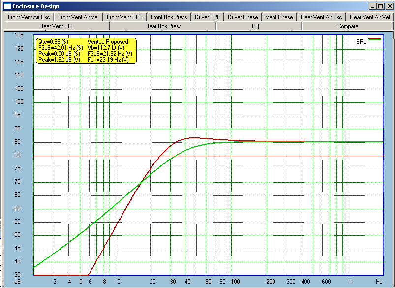
10” Woofer Ported Versus Sealed Response
The 2.2 cubic foot vented cabinet tuned to 27Hz was selected even though it represents a slight misalignment. Although a tuning frequency of 22Hz would have resulted in flatter response, the cabinet design limited the length of the port tube as lower tuning frequencies require longer ports. Note here that the sealed alignment in green would yield a pretty flat in-room response and is probably a better overall choice for many listeners. However, our goal of +/-3dB from 35Hz to 20kHz and high SPL could not be realized with a sealed enclosure. Most people have heard a woofer or two bottom out and it is important to consider how much abuse a woofer can take before employing it in a design. Once the T/S parameters are input and the enclosure is modeled, SoundEasy allows a designer to analyze acoustic phase, internal acoustic pressure on the box, port air velocity, group delay, phase and system sound pressure level. The Peerless woofer used in this design has a linear excursion of +/- 12.5mm. Below is a graph showing the expected cone excursion with a 150 watt input signal with the vented enclosure in red and the sealed enclosure in green. Note that this power level yields over 105dB sound pressure level before the driver rolls off for both enclosure types.
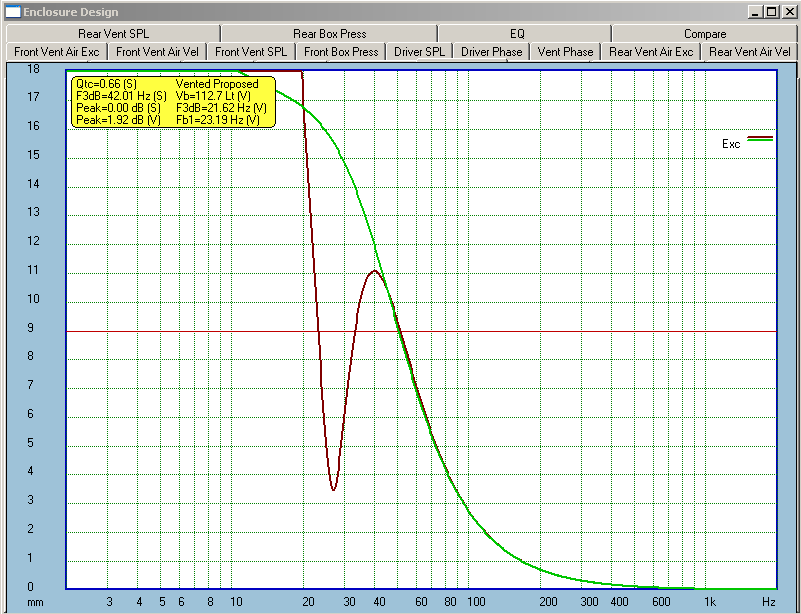
10” Woofer Ported Versus Sealed Excursion
Clearly, vented enclosures allow significantly more power handling above 20Hz but there is no free lunch here. Group delay is severely affected by the vented alignment and this means that vented enclosures are sometimes considered to have a less desirable transient response. Considering the majority of music content is above 40Hz, the group delay for the vented enclosure will suffice for this project.
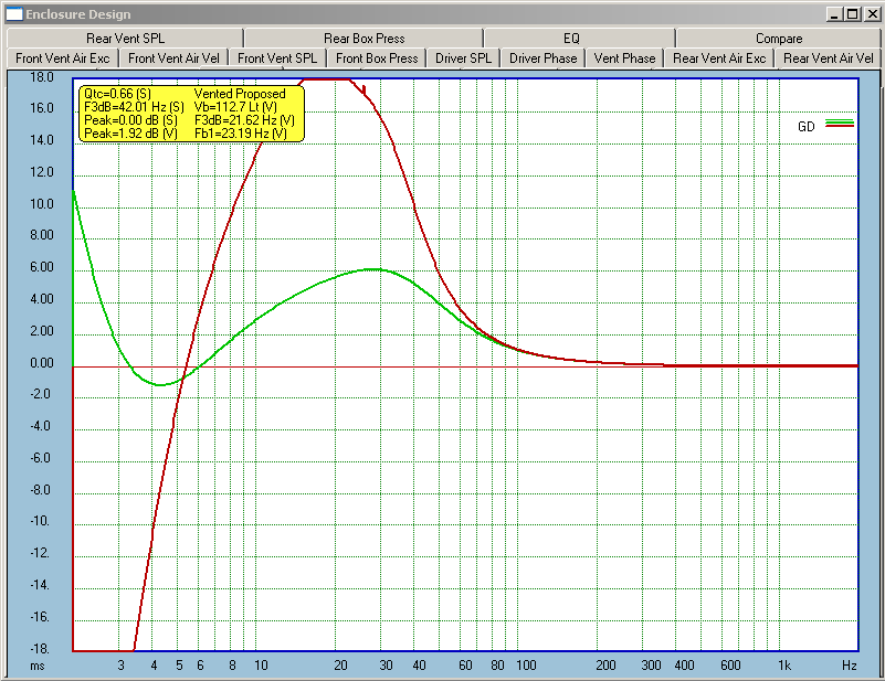
10” Woofer Ported Versus Sealed Group Delay
At this juncture, it is important to note that the T/S parameters from the loudspeaker manufacturers do not always match the actual T/S parameters. Many loudspeaker design programs and other tools allow extraction of the T/S parameters. If precision is key and you do not want to risk cutting cabinets or ports twice then it is important to determine the actual T/S parameters of a loudspeaker before moving forward with the design. It is often useful to model response using the manufacturer’s data sheet for a ballpark before purchasing a driver and then measure the actual T/S parameters before proceeding with the design using a program such as SoundEasy or Dayton Audio’s WT3 system.
Now that a suitable low frequency driver has been selected, it is typical to find a midrange that is more sensitive. Generally, the low frequency driver does not require too much response shaping so the critical midrange must have enough sensitivity headroom to allow for response manipulation if needed. Finding the right combination of woofer and midrange is critical and it is very important to know a few things here.
- The woofer to midrange crossover frequency can safely be increased as the woofer diameter decreases
- Higher woofer to midrange crossover frequencies typically equate to less expensive crossover parts such as smaller value capacitors and inductors.
- Large woofers crossed over too high have bad off axis response at higher frequencies
- The crossover frequency should be an octave or more away from any driver breakup modes
- The T/S Parameter
for resonant frequency (Fs) should be an octave below the desired crossover
frequency
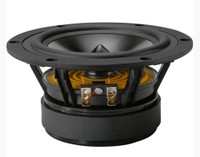
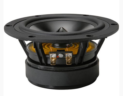
Some people love the sound of bookshelf speakers because the dispersion characteristics are difficult to duplicate by speakers with huge drivers. As with most things in engineering, the art of loudspeaker design is about selecting the set of tradeoffs that make the most sense for a given design goal. While it would be nice to design a 3-way passive loudspeaker with an 80Hz subwoofer to midrange-woofer crossover frequency, the crossover parts at this frequency are pretty expensive. This is one application where active crossovers have a huge advantage over passive crossovers. Since the Peerless XXLS woofer response gets a little funky above 700Hz, we will shoot for a crossover frequency a minimum of an octave below to reduce the amount of response shaping required. This means that the midrange selected for this project must have enough surface area and excursion to play well below 350Hz at a minimum of 100dB at one meter. Additionally, the midrange should have a resonant frequency less than 175Hz. Since I wanted the option to use a 2nd order crossover, a 5 or 6-inch mid-bass was required to meet the target specifications. The well-reviewed Dayton RS150-8 Reference 6” mid-bass is an 8-ohm driver with the necessary sensitivity, excursion, diameter and low resonant frequency required to meet the design requirements.
The tweeter selected for t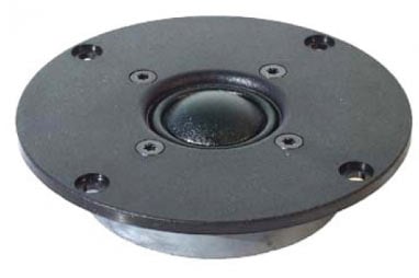 his project was the Seas
Prestige 27TDF. This tweeter was
selected because it is also well reviewed, has good power handling
specifications, is relatively linear and has a low enough resonant
frequency. It is important to select a
tweeter with a resonant frequency low enough so that the crossover frequency is
a minimum of two times the tweeter’s resonant frequency. The data sheet recommends usage beginning at
2.5kHz. Since the Dayton RS150-8
mid-bass driver is pretty large, crossing over as low as possible will provide
better off-axis dispersion. Given this,
we will attempt to design a crossover frequency of less than 350Hz for woofer
to midrange and 2.5kHz for midrange to tweeter.
Ultimately, the crossover frequencies may change depending on how the
drivers measure in the target cabinet.
With the drivers selected and T/S parameters for the low frequency
driver, we can begin designing a cabinet.
his project was the Seas
Prestige 27TDF. This tweeter was
selected because it is also well reviewed, has good power handling
specifications, is relatively linear and has a low enough resonant
frequency. It is important to select a
tweeter with a resonant frequency low enough so that the crossover frequency is
a minimum of two times the tweeter’s resonant frequency. The data sheet recommends usage beginning at
2.5kHz. Since the Dayton RS150-8
mid-bass driver is pretty large, crossing over as low as possible will provide
better off-axis dispersion. Given this,
we will attempt to design a crossover frequency of less than 350Hz for woofer
to midrange and 2.5kHz for midrange to tweeter.
Ultimately, the crossover frequencies may change depending on how the
drivers measure in the target cabinet.
With the drivers selected and T/S parameters for the low frequency
driver, we can begin designing a cabinet.
Building a DIY Speaker: Cabinet Design
Based on low frequency response models for the Peerless 83084 XXLS woofer, the desired cabinet volume for the woofer alone is 2.2 cubic feet tuned to 27Hz. To obtain this target volume, we have to also account for the volume needed for the RS150-8 midrange, volume of the port and the space occupied by the physical drivers in the system. Cabinet designs can be done by hand or preferably using 3D computer aided design (CAD) software such as SolidWorks or SketchUp. It is much easier to see what you are working with and make changes in CAD instead of having to recut cabinets. Books could be written on cabinet design, but here are some basic things to think about before starting.
- Rounding over the cabinet edge reduces peaks and troughs in frequency response around the baffle step diffraction frequency.
- Cabinet material and material thickness play a huge role in reducing the sound a cabinet makes. Medium density fiberboard is the standard material because it is relatively inert, readily accessible and is pretty easy to work with. Baltic birch and plywood are also popular choices. In most cases, 3/4” or greater wood thickness is recommended.
- Use plenty of internal cabinet bracing to reduce panel vibrations and space the bracing asymmetrically to reduce the effects of standing waves.
- Countersink all drivers, the diffraction effects of a surface mounted driver might surprise you.
- Chamfer the back of all open back driver cutouts to allow for better airflow behind the driver. This is typically required for all drivers except the tweeter.
- For 3-way systems, placing the midrange in a separate internal enclosure produces cleaner midrange performance. It is a good idea to slant the back of the midrange chamber to prevent reradiating sound from the back of the chamber through the midrange cone.
- Build enclosures a minimum of 10% larger than design requires as it is easy to fill dead space but hard to create volume once it is built
- Determine proper port tuning by starting with a longer than calculated port tube length and reduce the port tube length to meet the target port tuning by measuring either impedance or acoustic output of the port.
- Use flared port that is flared on both ends and has adequate diameter for the proposed vented enclosure and expected sound pressure levels.
- Expect to invest a minimum of 3-5 full days of work for a high quality tower loudspeaker cabinet.
D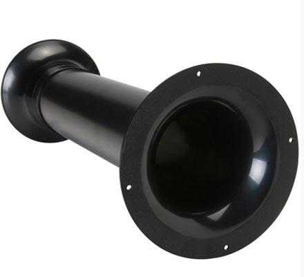 etermining
the port parameters for a cabinet is not complicated but it is best to use a
calculator on the manufacturer’s website.
Flared ports are not all the same and reaching the target tuning
frequency is easy to determine by plugging in the necessary parameters into the
manufacturer’s website. Just note that
it is best to leave the port tubes a little long and trim to reach the target
tuning frequency. Tuning an internal
volume of 2.2 cubic feet to 27Hz requires a port tube that is approximately 9.7
inches long for a 3-inch diameter port.
This port occupies approximately 0.04 cubic feet so the internal cabinet
should account for the port volume.
Also, it is important to determine the volume of internal bracing and
estimate the volume of the drivers protruding into the cabinet. When all is
said and done, add an additional 10% to the calculated required internal
cabinet volume. Once the internal volume
is determined, it is pretty simple to determine the required cabinet
dimensions. Standing waves are greatly
reduced when cabinet internal dimensions are not the same or multiples of the
same distance apart. If you are brave, non-parallel walls should yield even
better results. For this project, the
midrange is placed in a separate sealed space that is not included in the
woofer cabinet volume calculation. The
midrange chamber benefits from non-parallel walls as well. It is a good idea to run simulations on the
midrange driver in the intended enclosure to confirm the enclosure size will
not negatively effect frequency response.
etermining
the port parameters for a cabinet is not complicated but it is best to use a
calculator on the manufacturer’s website.
Flared ports are not all the same and reaching the target tuning
frequency is easy to determine by plugging in the necessary parameters into the
manufacturer’s website. Just note that
it is best to leave the port tubes a little long and trim to reach the target
tuning frequency. Tuning an internal
volume of 2.2 cubic feet to 27Hz requires a port tube that is approximately 9.7
inches long for a 3-inch diameter port.
This port occupies approximately 0.04 cubic feet so the internal cabinet
should account for the port volume.
Also, it is important to determine the volume of internal bracing and
estimate the volume of the drivers protruding into the cabinet. When all is
said and done, add an additional 10% to the calculated required internal
cabinet volume. Once the internal volume
is determined, it is pretty simple to determine the required cabinet
dimensions. Standing waves are greatly
reduced when cabinet internal dimensions are not the same or multiples of the
same distance apart. If you are brave, non-parallel walls should yield even
better results. For this project, the
midrange is placed in a separate sealed space that is not included in the
woofer cabinet volume calculation. The
midrange chamber benefits from non-parallel walls as well. It is a good idea to run simulations on the
midrange driver in the intended enclosure to confirm the enclosure size will
not negatively effect frequency response.
This project was designed in SolidWorks but could easily be done in Google SketchUp. The 3D CAD programs allow for easy calculation of internal volume and are really handy for test fitting drivers and ports before building the cabinet. I once designed a simple sub cabinet but didn’t realize the port length would interfere with the driver until the cabinet was finished. I ended up rerouting the port using a series of bends that ended up causing port noise when the volume was cranked.
In this project, we used 3/4” Baltic birch with a 3/4” MDF baffle and bottom plate. This was selected because the loudspeaker sides were subsequently covered with album covers and Lexan for a unique finish. The panels were cut using a table saw and all chamfering and circular cutouts were completed using a quality plunge router. A circle-cutting jig is a worthwhile investment as it provides accurate results in short order. The bottom of this speaker is removable with weather stripping between the detachable bottom and the rest of the cabinet. A bottom firing port is attached to the bottom plate, which requires 2-3 inch long feet or spikes for clearance. Although it is probably obvious, it is highly recommended to test fit everything before final assembly. When test fitting drivers, it is a good idea to drill holes and use hurricane nuts to allow secure mounting and remounting of drivers. It is also recommended to use biscuit joints when gluing panel walls together although it is acceptable to use screws to hold panel walls together for gluing. Once the glue is cured, all screws should be removed. For this project, the baffle, bottom and back of the speaker were spray painted. Spray painting MDF is time consuming because it requires several iterations of sanding and painting to obtain a smooth finish since MDF absorbs some paint, especially on corners that are rounded over. Finally, album covers were glued to the cabinet and the covers were protected with a thin layer of Lexan.
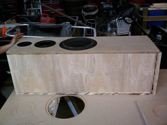
Test Fitting Drivers
Here is a list of materials and tools needed to pull off a typical cabinet build.
- 3/4” Medium Density Fiberboard
- Wood Glue
- Wood Screws
- Hurricane Nuts and Bolts for Driver Mounting
- Acoustic Stuffing
- Flared Port Tube
- Binding Posts or Terminal Cup
- Carpet Spikes or Feet
- Electric Sander and Sandpaper
- Cordless Drill
- Drill Bits
- Biscuit Cutting Tool and Biscuits
- Table Saw with Solid Gate and Sharp Blade
- Plunge Router
- Series of Chamfer Bits for Router
- Series of Round Over Bits for Router
- 1/4” Straight Cutting Bit for Router
- Circle Cutting Jig for Router
- Tape Measure
- Framing Square
There are a large number of possible finishes for a DIY loudspeaker project. I have had success with paint and real wood veneer but both require a little practice and much patience. Once you have decided on a finish, do some research to determine a good application method. I’ve never gotten a finish right the first time, so practicing on scrap material is highly advisable.
Building a DIY Speaker: Crossover Design
The crossover design can make or break any multi-way loudspeaker. Having the world’s best drivers with a poor crossover design will yield poor results. It is important to approach crossover design with humility because it truly is an art that requires experience to perfect. Yes, it is possible to get decent sound by sending driver data sheets off for a generic crossover design. However, without proper analysis of the drivers in the intended cabinet it is a game of roulette. This design overview neglects many design considerations a professional designer may consider such as time alignment, distortion and polar response but provides a starting point.
Before designing a crossover, the cabinet must be fully assembled including ports and drivers. I typically run a separate speaker wire from each driver out of the port and label each wire. For sealed loudspeakers, connect the woofer to the binding post as this is the first driver measured in the cabinet. Using SoundEasy, each driver is measured in the cabinet to obtain frequency response and electrical impedance. These parameters are obtained following the test methodology outlined in our Loudspeaker Measurement Standard. Please note that any measurements taken near field must factor in the effects of baffle diffraction. SoundEasy allows modeling and application of baffle diffraction estimates to any frequency response data. Getting good measurement data is one of the hardest parts of loudspeaker design. It is crucial to validate your results by taking measurements using both near field and quasi-anechoic gated techniques and compare the measurements before proceeding. The measurement data is subsequently used in SoundEasy’s crossover design tool.
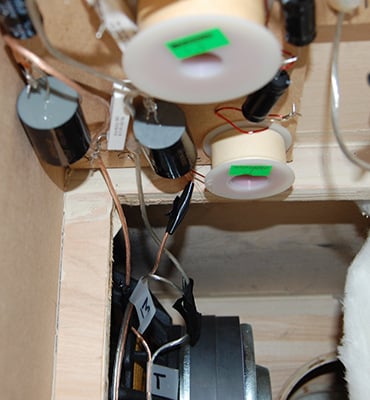
DIY Crossover Installed in Cabinet
Although CAD has come a long way, designing a loudspeaker crossover benefits from some background in electronics. SoundEasy has 2-way to 5-way crossover templates covering 1st order to 4th order crossover topologies. Additionally, there are templates for a wide array of typical filters and compensation circuits. The CAD framework allows implementation of any circuit or filter topology imaginable so long as it uses inductors, resistors, capacitors, operational amplifiers, potentiometers or logic gates. If you have not ever studied filter design or do not know what the previously-mentioned elements are, you may want to consider studying up to improve your chances of pulling off a working and affordable solution.
The first step I take when designing a crossover in SoundEasy is to determine workable crossover frequencies and filter orders. This requires careful inspection of the driver data sheets, frequency response measurement and driver impedance. It is imperative to make sure that response anomalies, such as the breakup of a metal cone driver, are sufficiently attenuated by the crossover so that they are not audible. It is generally a good idea to keep the crossover frequencies low enough to prevent driver beaming but high enough to prevent driver failure. For example, crossing over most tweeters below 1.5kHz is a bad idea if it is meant to play program material at 110dB or has a resonant frequency above 750Hz. Crossing an 8 inch bass driver at 5kHz will result in poor dispersion and transient response at higher frequencies. As a rule of thumb, the max frequency for a given driver diameter can be equated by taking 13560 and dividing it by the drivers effective diameter. For an 8” driver with an effective cone diameter of 7”, this means that the maximum crossover frequency should not exceed 1937Hz.
A 4th order crossover rolls off frequencies at 24dB per octave where as a 1st order crossover rolls off frequencies at 6dB per octave. Lower order crossovers have less phase shift but tradeoff power handling and masking out of band response anomalies. The designer has to determine the best set of tradeoffs for an intended design goal. SoundEasy has built-in filter templates for delay networks if a designer desires to design a time aligned loudspeaker for higher order filters. It is also important to note that the filter order does not have to match for each driver in a system but it does simplify the design.
Once approximate crossover frequencies and filter orders are determined, a filter can be developed in CAD. For the purposes of this design analysis, a 2nd order crossover was designed which approximately matches a Butterworth filter target. Additional response shaping elements were added where needed to meet the design requirements. This circuit was determined based on using a 2nd order low-pass for the woofer, band-pass for the midrange and high-pass for the tweeter. Due to the response anomalies and differences in sensitivity, additional elements were added. The final circuit design is shown below.
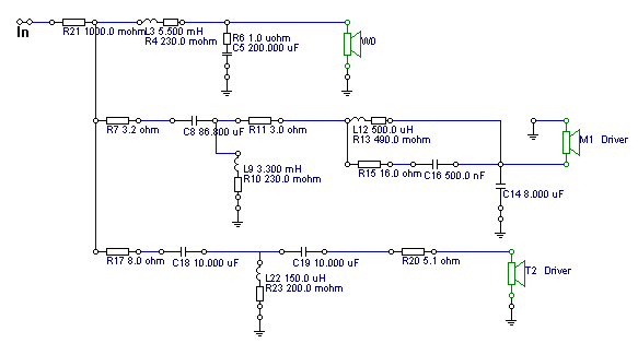
Crossover Circuit in CAD
The component values for the circuit design are determined using SoundEasy’s ingenious optimization technique. It is as simple as setting a target response for a single driver and selecting the components SoundEasy should manipulate to attempt to meet the target response. In this example, a 2nd order Butterworth band-pass filter target was setup in the optimization dialog as shown in black in the figure below. SoundEasy will modify the selected crossover components and employ trial and error to arrive at the optimum component values required to meet the frequency response target. The optimization technique will attempt thousands of combinations and may be run multiple times to determine the best component values. While running optimization, it is important to pay attention to the component values set by SoundEasy because it may set values that are very high inductances or capacitances and therefore expensive. This may take some playing around to get right. If you are unable to get close to the target curve you might consider changing the filter topology. The midrange for the sample project tracks the target curve pretty well but is not perfect at the high frequency knee due to response problems with the driver itself. It is possible to shape the response further but more crossover components equate to a more expensive crossover. It is easy to spend hundreds or even thousands of dollars on crossover components. It is often better to solve extensive frequency response problems with better drivers or a more in-depth diffraction analysis.
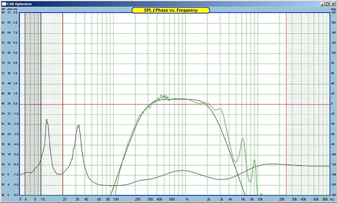
Midrange Crossover Optimization
The optimization process is applied to the low-pass, band-pass and high-pass filters and a combined response is generated. Due to response issues, it may be necessary to attenuate a target or move the crossover frequency slightly to obtain a flatter response. Ultimately, it may take several rounds of moving crossover frequencies and even filter orders to get to an acceptable system response. The combined system response after optimization for this design is shown below.
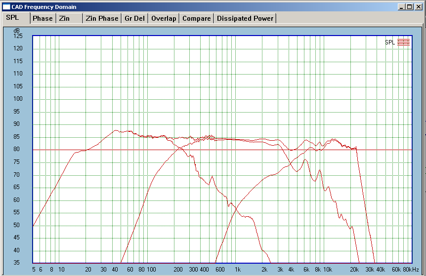
3-Way Crossover Summed Response
During the design process, it is important to pay close attention to system impedance graphs. It is no fun perfecting frequency when your design has a minimum impedance of 1.5 Ohms. SoundEasy has an option to set the minimum acceptable impedance during optimization to help reduce the risk of developing a network that dips too low for the amplifier you are using.
As a final step, it is absolutely necessary to set the values of capacitors, resistors and inductors in the CAD editor to values you can actually purchase. This usually involves rounding up or down to values you can purchase. If the crossover parts are expensive, you can attempt to reduce component values and subsequently plot their effect on the final response. This is time consuming but can save you a ton of money. A 3-way crossover of this complexity is not cheap. Using cheap electrolytic capacitors this crossover costs close to $150 for components alone.
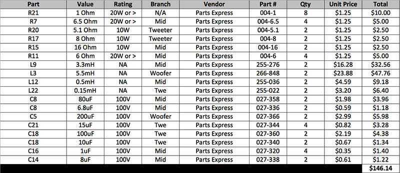
3-Way Crossover Bill of Materials
Conclusion
Unfortunately, the tweeter used in this design did not measure close to the data sheet at all and required pushing the crossover frequency up. Ultimately the dip at 4kHz is fixable but the cost required outweighs the benefit.
Personally, I prefer loudspeakers that have a frequency response that tilts slightly downward so I find the response of this speaker pleasing. It did not ultimately meet the design goal of +/-3dB frequency response deviation but it plays low bass with authority and sounds very good overall. Even though it is a ton of work, there is something very rewarding about designing a loudspeaker from the ground up and the owner of the speakers discussed in article is extremely happy with his one of a kind creation.
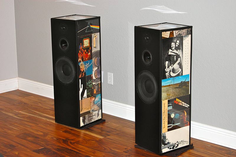
DIY speaker Finished Product
Ultimately, designing your own loudspeaker is something you do because you like the creative side of designing things. If you are after bang for your buck sound, it is much cheaper and less time consuming to use someone else’s well-established and well-documented DIY design with pre-fabricated cabinets.
Some of my personal favorites include:
- http://www.linkwitzlab.com - Siegfried Linkwitz is a renowned loudspeaker designer that develops DIY loudspeaker projects for fun in his retirement. The new LX521 and older Orion loudspeaker projects are considered by some to be among the best speakers available, even commercially.
- http://www.troelsgravesen.dk - A Danish designer responsible for many well regarded mid to very high end DIY designs. Most require building a cabinet but the designs represent very high value.
- http://zaphaudio.com - Although this site is not updated much anymore, John Krutke has many good designs available as full kits. He has also tested a slew of drivers if you need unbiased raw driver data.
- http://parts-express.com - Many full DIY kits and parts available directly from Parts Express
- http://madisound.com - Many full DIY kits and parts available directly from Madisound. They also offer a crossover design service using very good crossover design software.
Joel Foust's experience in quality control, product certifications and do-it-yourself loudspeaker design bode well for the consistent application and development of in-depth loudspeaker testing. Joel is committed to providing accurate results that are comparable for each loudspeaker tested.
View full profile