
Audioholics Reference System 2
CinemaSITE Reference System
Some people build cars, others work on boats… As an official Audioholic, my passion has been for consumer electronics for quite some time now. While boats and cars can be hidden away in garages (or front lawns depending upon what part of the country you live in), home theater projects take on a considerably more sensitive nature in that your living space takes the brunt of the disruption. Fortunately, as any Audioholic knows - a complete rebuild must take place in as short a period of time as possible, so as to more quickly resume home theater bliss. Tweaking is another story. Once the room is done, ask the housewife of any true Audioholic and you'llfind that constant tweaking is pretty much the status quo.
Enter Reference System 2. With various adjustments being made at Audioholics, Reference System 2 was due for a location change as well as a complete rebuild. Absolutely nothing - not one solitary component - would remain from the original system. In addition, we planned on bringing in Rives Audio and RPG Acoustics to ensure that the newly renovated room would provide a sufficient evaluation environment for reference level products.
Building a Moderately Priced HT - Want My Job?
Building a new reference room sounds like the greatest opportunity in the world, right? I'll tell you what, we'll have some fun. You come over to my house and take a piece of paper. On it write the dimensions of the room, all of the equipment that is needed for a full AV experience, the necessary room acoustic treatment, and the full accompaniment of cables required to make everything work together (and still be flexible enough to allow for additional product reviews without tearing the room apart). Then prep and paint the room; make everything work together; complete the full install of cables, equipment and acoustics; and clean it all up. I'll supply the pencil, tools and soft drinks. OK, so it is sort of fun. The fact that this is a dedicated theater room (where I also conduct and write reviews) helped quite a bit - especially since it took several months of hard work and design time to get from start to finish.
In writing this article I decided to attempt to document the tips, tricks, and shortfalls I ran into during the course of turning my former 13.3 x 16 office into Reference System 2. It is my hope that perhaps some of my experiences will lend some help to those looking to enjoy the same result - a complete home theater system that will dazzle guests and satisfy even the most hard core music and movie lovers.
Planning, Planning, Planning
![[CONCEPT1cu]](../../../../images/concept1cu.gif) When starting in on a project of this scope, it's important to fully plan your adventure. Even if things change along the way (and they will) if you have a written plan, you can get a good handle on things and where you stand in the process (not to mention control your costs). My particular project plan included the following:
When starting in on a project of this scope, it's important to fully plan your adventure. Even if things change along the way (and they will) if you have a written plan, you can get a good handle on things and where you stand in the process (not to mention control your costs). My particular project plan included the following:
• Room dimensional drawing & room mode analysis
• Speaker placement diagram
• Identify compromises and design constraints
• Complete AV and power wiring diagram
• Equipment list (existing and required purchases)
• Room acoustics drawing and evaluation (provided by Rives Audio)
Room Dimensional Drawings & Room Mode Analysis
While the first two items were taken care of early on by myself and Rives Audio, it was very important to get the room dimensions and room mode analysis correct in order to proceed with the full room design. The reason we start here, of course, is to determine the room modes (which will be significant and present in any small room) and determine the best location for seating. While Rives keeps the room mode analysis to themselves and simply provides the final room recommendation, we'll go ahead and show you the calculations here. The formula for calculating room mode frequencies is:
F = m 1130/2D
Where:
F = frequency of the resonance mode in Hz
m = mode harmonic (first = 1, second = 2, third = 3, etc)
D = distance between two parallel surfaces in feet
1130 = approximate speed of sound in feet/second
So in the case of Reference System 2:
|
Room Mode |
16.0 (L) |
13.3 (W) |
9.0 (H) |
|
First |
35.3Hz |
42.5Hz |
62.8Hz |
|
Second |
70.6Hz |
85Hz |
125.6Hz |
|
Third |
106.9Hz |
127.4Hz |
188.3Hz |
|
Fourth |
141.3Hz |
169.9Hz |
251.1Hz |
As you can see by this chart, there are some second and third harmonic room mode issues to be taken into consideration at approximately 126Hz. Overall, we did well with these dimensions - especially considering this room was pre-existing and not new construction. We mapped out the seating accordingly and made sure to position the theater chairs in a position that avoided the worst of these modes for all seating positions. Every home theater room is going to have to deal with these types of issues to some extent. Depending upon your budget, you can all but completely eliminate the effects of room modes on the main listening positions, or you can work to ensure that at least the biggest problems are avoided.
A full Level 2 Room analysis from Rives Audio (for existing or new construction) costs $2,250 but may be the most important aspect of your home theater design. In level 2, one of Rives' dealers or representatives takes actual acoustical measurements of the room. The acoustical measurements gives them valuable information such as actual frequency response, reverberation times, and energy time functions. While these terms may seem foreign to some people, these measurements increase the precision in designing the listening room.
After completing the application form, Rives will call to get a complete understanding of your needs and limitations. Some people have to integrate the listening room into a family room and do not want unsightly room treatment. Others, may have the luxury of a dedicated room and don't care about the aesthetics, but want the best possible sound at a reasonable price. Rives Audio works well with both scenarios.
Rives develops a concept plan which includes the likely treatments that will be used. Once approved, calculations and a full schematic are generated. These have complete assembly drawings and a report giving objectives of the sonic benefits they expect to achieve. Most of their designs use standard building materials, where the material cost is relatively modest. Construction can be done by the individual in or a contractor.
The biggest challenge in designing a room is achieving the right balance of all the devices. This is where having a company like Rives do the designs makes sense. Since Rives Audio does dozens of designs a month and hundreds a year, their engineers have over 30 years experience in the business. This insures that reverberation times, frequency response, and energy held in the room can be a systematically and intelligently handled and factored.
Building a Moderately Priced HT - Speaker Placement Diagram
![[Speaker]](../../../images/diagram.gif/image) Loudspeaker layout should be a simple process as long as you understand a few basic principles. While there are a myriad of options, the principles of good loudspeaker positioning are relatively constant for home theater. Unlike some, who recommend full range speakers placed in a near-field configuration around a single listening position, Audioholics' stance is more of an "every seat is a good seat" approach. It does no good, in our opinion, if a home theater has a single "golden seat" and your guests (or significant other) are sitting in a bass mode or in a place where the surrounds become distracting and the soundstage is collapsed. As a result, we recommend dipole or similarly diffuse speakers for the side surrounds and careful subwoofer placement to alleviate the effects of the room's natural standing waves (bass modes). Please see our article on subwoofer placement guidelines for an expanded view on this topic. When possible, three matched speakers for the front soundstage are best (with a "behind the screen" center channel being a good way to accomplish this) but we recognize, as in the case of the RBH Sound CinemaSITE, that there are necessary exceptions and alternatives that may employ a different center channel. In these cases, we simply recommend (though insist would be more appropriate) that the center channel be very compatible with horizontal placement with careful consideration given to correct horizontal and vertical dispersion as well as timbre matching the main speakers.
Loudspeaker layout should be a simple process as long as you understand a few basic principles. While there are a myriad of options, the principles of good loudspeaker positioning are relatively constant for home theater. Unlike some, who recommend full range speakers placed in a near-field configuration around a single listening position, Audioholics' stance is more of an "every seat is a good seat" approach. It does no good, in our opinion, if a home theater has a single "golden seat" and your guests (or significant other) are sitting in a bass mode or in a place where the surrounds become distracting and the soundstage is collapsed. As a result, we recommend dipole or similarly diffuse speakers for the side surrounds and careful subwoofer placement to alleviate the effects of the room's natural standing waves (bass modes). Please see our article on subwoofer placement guidelines for an expanded view on this topic. When possible, three matched speakers for the front soundstage are best (with a "behind the screen" center channel being a good way to accomplish this) but we recognize, as in the case of the RBH Sound CinemaSITE, that there are necessary exceptions and alternatives that may employ a different center channel. In these cases, we simply recommend (though insist would be more appropriate) that the center channel be very compatible with horizontal placement with careful consideration given to correct horizontal and vertical dispersion as well as timbre matching the main speakers.
The final complement of loudspeakers which had to be configured into Reference System 2 included:
- RBH Sound Signature SI-6100 for front and center speakers (located within the CinemaSITE enclosure)
- RBH Sound Signature SI-1010P subwoofers (located within the CinemaSITE enclosure) powered by dual SA400 amplifiers
- RBH Sound Signature 66-SE hybrid surround loudspeakers (in-phase midrange drivers with dipole configured tweeters)
- RBH Sound Signature 41-SE surround back speakers
Additional loudspeakers can be used within the reference system through redundant speaker connections which were placed in strategic areas throughout the room. We did this to better facilitate testing and bringing manufacturers' products into the room without having to completely disassemble the RBH Sound CInemaSITE.
Identify Compromises and Design Constraints
Unless you are designing and building from the ground up you will likely have to identify, preferably early on in the process, particular design constraints associated with the home theater project. For some this will include issues such as ceiling height, doors & windows, compounding room modes, construction materials and budget limitations. With Reference System 2, the largest constraint was its intended "dual-use" configuration. While a dedicated home theater is typically the best solution, I wanted to be able to co-exist within RS2 and conduct measurements, write reviews and perform all of the functions associated with evaluating consumer electronics equipment. It not only made ergonomic sense, but the net result is that I can co-exist with the equipment I am evaluating and writing about.
Attempting to allow both uses to share the room space brought up some interesting issues and challenges, including the following:
- Additional networking and power requirements were needed in a second room location
- The listening positions had to be moved forward slightly to accommodate a desk
- A second row of seats was impossible
- Seated distance to the screen was decreased, resulting in a potential issue for lower resolution projectors (a minimum requirement for any projector was acceptable resolution with a screen width that was 1.5x the seating distance).
- Rear closet doors mandated a slightly higher-than-normal mounting position for the surround back speakers.
- A mandatory in-room projector location required a very quiet projector so as to not allow noise to distract from the viewing experience.
- A whole lot more cabling was going to be required to make everything run smoothly (we turned to Impact Acoustics to help us with this particular aspect of the room)
In addition to these constraints, we imposed some additional considerations when selecting the RBH Sound CinemaSITE as our reference loudspeaker system:
- The twin SI-1010P subwoofers are in fixed locations, resulting in the inability to use subwoofer placement to reduce the effect of room modes/standing waves
- A behind-the-screen center channel was not yet possible so we needed to utilize a below-the-screen center channel specially configured for that system and correctly aimed towards the listening position.
As you'll see, these design constraints were more than tolerable and we utilized a combination of speaker placement, speaker aiming, phase adjustment and EQ to correct for any anomalies caused by our particular scenario.
Building a Moderately Priced HT - Complete AV Power and Wiring Diagram
![[Wiring]](../../../images/rs2wiring.gif/image) Before you go drilling holes or purchasing your wiring you'll need a diagram outlining the requirements to completely satisfy the operating parameters of the theater room. This was one of the starting diagrams we began with and it outlined the runs needed to accommodate the revised home theater setup as well as the workstation which exists just behind the listening position. We decided early on to go with Impact Acoustics to gather all of the speaker, networking, and interconnect wiring we'd need to complete this job correctly. Color coding helped identify what type of cables were required and made double checking the master cabling diagram much easier.
Before you go drilling holes or purchasing your wiring you'll need a diagram outlining the requirements to completely satisfy the operating parameters of the theater room. This was one of the starting diagrams we began with and it outlined the runs needed to accommodate the revised home theater setup as well as the workstation which exists just behind the listening position. We decided early on to go with Impact Acoustics to gather all of the speaker, networking, and interconnect wiring we'd need to complete this job correctly. Color coding helped identify what type of cables were required and made double checking the master cabling diagram much easier.
We elected to run loudspeaker cables to the front and make the terminations accessible for us to swap out with products that we would later test. I mapped out the front channels, surrounds, and rear surrounds which were all speaker level cables. The line level subwoofers came next and we ran an additional cable for a third sub to allow us to test a manufacturer's subwoofer from the front of the room. Next we mapped out RF cable runs as well as RJ45 and phone jacks. We finished by running HDMI and component video (not pictured) to the projector location on the ceiling.
All of the equipment was to be located in a closet at the rear of the room. An RF-based remote control system with IR blasters would be used to control everything as line-of-sight IR use would be impossible. Locating the equipment in the back of the room allowed us to utilize more of the front space for loudspeakers - a requirement when installing the CinemaSITE into a 13.3' wide room.
Editor's Note on Wiring
Wiring is a tricky thing. You want to ensure you have reliable cables, after all you aren't going to want to ever run them again - especially not the ones that are permanently located behind walls, in conduit, or underneath crown molding. You do not, however, have to purchase super-expensive cables to get a reliable solution. We found that Impact Acoustics offered a tremendous value overall for cables which not only looked good, but performed well. They also had the added advantage of being able to provide all of the connectors, wall plates and types of cabling we required for nearly the entire AV install. For our digital video cabling, we turned to DVIGear, who makes the best long-distance copper run cabling we've seen to date. Their SHR HDMI cables fit the bill and allowed us to get from our equipment closet to the front projector neatly and with wall (for the ceiling in our case) plates that made terminating the cables on each end a very simple process.
Our Laundry List for Cables from Impact Acoustics
Cables
Type
Model
Subwoofer cables
RG6 coax
IA
Speaker cables
12/2
IA
Networking cables
RJ45 Cat5e
IA
Analogue audio interconnects
RCA stereo
IA
Component video interconnects
YPrPb
IA
Digital audio coax interconnects
S/PDIF Coax
IA
Wall Plates & Connectors
Type
Model
Speaker cable terminations
Binding posts
IA
Subwoofer line terminations
RCA
IA
RJ45 cable termination
Cat5e
IA
Cable (RG6) termination
F-connector
IA
Digital Video (HDMI) Cables from DVIGear
Cables
Type
Model
SHR HDMI cables
12.5m SHR HDMI
DVIGear
HDMI & Component wall plate
Wall plate
DVIGear
Building a Moderately Priced HT - Equipment List
Now that we outlined our room and wiring plan, we were ready to complete the equipment list by adding in the equipment we would need to complete Reference System 2. This included bringing in some new pieces of reference equipment to ensure the room was up to speed and ready for use in testing new products for our readers. The required equipment included HDMI capable display products, up-to-date receivers and sufficient power to run the RBH Sound CinemaSITE (whose components we detailed earlier in this article). For our needs we spec'd out the following:
| Component |
Brand | Model |
MSRP |
| Level 2 Acoustics Plan | Rives Audio | NA | $2,250 |
| Loudspeakers | RBH Sound | CinemaSITE | $27,000 |
| Subwoofers (2) | RBH Sound | SI-1010P In-walls | $3,200 |
| Receiver | Denon | AVR-5308CI | $5,500 |
| Blu-ray Player (universal) | Oppo | BDP-83 | $499 |
| Front Projector | Epson | Pro Cinema 9500UB |
$3,999 |
| Projector Mount | Peerless | PRG-UNV + acc. |
$450 |
| 7-channel Amplifier | Emotiva | DMC-1 | $1,999 |
| 92" Screen Masking System |
Carada | Masquerade | $2,916 |
| Power Conditioner/Regulator | APC | S-15/SBATT |
$1,999 |
| Game Console | Microsoft | Xbox 360 |
$299 |
| Home Theater Seating | Berkline | 088 with leather | $2999 |
| High Definition DVR | DISH Network | VIP 722 | (lease) |
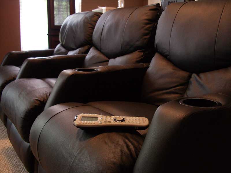
| Remote Control | URC | MX-3000/MSC-400 | $1999 |
| Total Cost | $55,109 |
Whew, we're glad we saved up our pennies. This isn't exactly a small shopping list of equipment we've put together for our home theater reference room.
Room Acoustics Drawing & Evaluation (Provided by Rives Audio)
![[Acoustics]](../../../images/acoustics.gif) The additional (but not necessarily last) step needed before executing the room construction was to consult with a knowledgeable and reputable acoustical design firm. This helped determine the best design for the room as well as room acoustic treatments that would aid in getting a much improved listening experience for all seating positions. We selected Rives Audio for this task and had them do a Level Two Room Acoustics Consultation which included having them evaluate and model our room to determine proper acoustic materials and seating positions. We supplied them with our room dimensions, window and door positions, and any design limitations or preferences that would otherwise affect their acoustical design. What we received back was a clear-cut plan to follow in order to best arrange and treat our room.
The additional (but not necessarily last) step needed before executing the room construction was to consult with a knowledgeable and reputable acoustical design firm. This helped determine the best design for the room as well as room acoustic treatments that would aid in getting a much improved listening experience for all seating positions. We selected Rives Audio for this task and had them do a Level Two Room Acoustics Consultation which included having them evaluate and model our room to determine proper acoustic materials and seating positions. We supplied them with our room dimensions, window and door positions, and any design limitations or preferences that would otherwise affect their acoustical design. What we received back was a clear-cut plan to follow in order to best arrange and treat our room.
Rives Audio worked around our physical and design limitations (there were a few grumbles about the locked-down subwoofer positions!) and placed the room acoustics accordingly around the room. They also laid out the optimal surround speaker positions and gave us a full set of plans by which to proceed with the room. For anyone wanting to really design a home theater room, this is a step that cannot be ignored. Failing to implement good room acoustics will only result in a room that has a bunch of gear in it and perhaps a large screen that will likely look better than it sounds. If you want your movies and music to sound their best, this is not a place you want to skimp.
Building a Moderately Priced HT - The Build-Out
OK, let's start with the first, and most involved, part of the process… wiring. In order to get all of the wiring from one side of the room to another you'll need to either go through the attic (if you have attic access above the room), through the crawl-space (if your home has that type of access), or run the cabling through baseboard or crown molding. This is one of my favorite tricks, and while there are products available like Wiretrax which make this a simply process, others may want a more custom solution made possible by utilizing standard crown molding and furring strips. As I needed more space than normal, this latter method is the one I utilized in Reference System 2.
The basic premise is simple:
- Purchase crown molding and furring strips
- Cut to fit
- Run cabling around the top of the room and drop down into the wall (behind the crown molding) where you need to get the cable to the floor
- Add wall plates to dress up your cable drop points
- Cover and secure with crown molding, caulk, and paint
Editor's Note on Crown Molding
Anyone who thinks cutting crown molding is a straightforward and easy task is either a professional trim carpenter or a fool. Do yourself a favor and purchase a crown molding measurement kit that includes the necessary protractors and calculators to get you the correct compound angles needed to make the complex cuts. In addition, this is the perfect time to purchase that electric compound miter saw from Sears or Amazon.com.
To begin, measure the room and purchase the required amount of crown molding as well as an equal amount of 1x2 furring strips which you will nail to the wall. This provides an alcove in which to store cables and is the rigid structure to which you will secure your crown molding. There are several programs online which can help you find the compound miter cuts required for crown molding or you can get a coping saw and utilize a different method which cuts the shape of one of the pieces into the other. I can't really teach a carpentry class in this article, so I'll leave it to you to educate yourself on the finer parts of woodworking - just don't underestimate the difficulty of this job.
![[Wires1]](../../../images/furringstrips.jpg) Once you tack up the furring strips, then running the first wire is the trickiest part of the process. This will be your "anchor" wire from which everything else will attach. Run this wire carefully and secure it every couple of feet to ensure a solid connection to the furring strips. Be sure to keep the cables high, so that there is no chance you will accidentally nail into them when you secure the crown molding to the wood. Leave spaces, or gaps in the furring strips where you need to drill holes to go down inside the wall for your cable drops. Notice that these holes will allow your cables to enter the wall from behind the crown molding, thus creating a nice, neat look that will have many wondering how on earth you ran wires without going under the carpet or without ripping up the room.
Once you tack up the furring strips, then running the first wire is the trickiest part of the process. This will be your "anchor" wire from which everything else will attach. Run this wire carefully and secure it every couple of feet to ensure a solid connection to the furring strips. Be sure to keep the cables high, so that there is no chance you will accidentally nail into them when you secure the crown molding to the wood. Leave spaces, or gaps in the furring strips where you need to drill holes to go down inside the wall for your cable drops. Notice that these holes will allow your cables to enter the wall from behind the crown molding, thus creating a nice, neat look that will have many wondering how on earth you ran wires without going under the carpet or without ripping up the room.
![[Wires2]](../../../images/cornerties.jpg) I found that pulling cables from a pull box or spool is easiest and you'll want your starting point to be at the cable termination side as you move towards the equipment closet. Basically pull out a bunch of cable and then move the pull box or spool towards the equipment room. Insert the cable into the hole and fish it down the wall (use fish tape in walls that have insulation - this is, on occasion, only slightly harder than pulling a Volkswagen Beetle through your left nostril). For those of you working on interior walls, count your blessings. As the cables pile up, secure each to the previous bundle with tie wraps and secure individual cables to the furring strips as you go. When I got to the equipment closet the cables were a pretty large mass (they accumulate as you go due to the mains meeting up with the surrounds, etc). I found that splitting up the feed into two or more cable bunches was far easier than trying to jam the entire mass through a single hole cut through the wall.
I found that pulling cables from a pull box or spool is easiest and you'll want your starting point to be at the cable termination side as you move towards the equipment closet. Basically pull out a bunch of cable and then move the pull box or spool towards the equipment room. Insert the cable into the hole and fish it down the wall (use fish tape in walls that have insulation - this is, on occasion, only slightly harder than pulling a Volkswagen Beetle through your left nostril). For those of you working on interior walls, count your blessings. As the cables pile up, secure each to the previous bundle with tie wraps and secure individual cables to the furring strips as you go. When I got to the equipment closet the cables were a pretty large mass (they accumulate as you go due to the mains meeting up with the surrounds, etc). I found that splitting up the feed into two or more cable bunches was far easier than trying to jam the entire mass through a single hole cut through the wall.
![[Wires31]](../../../images/wires31.jpg) Terminating the cables at the wall can be easily done through the use of wall plates such as those available from Impact Acoustics. Low voltage boxes are available from Home Depot, Lowes, or your local hardware store and enable you to install them into existing construction, providing a clean place for you to attach Decora-style covers to go over your Impact Acoustics wall plate connectors. Here I utilized a triple-gang box where I terminated the front loudspeaker channels, three subwoofer lines, an RJ45 connection, a phone line and cableTV line. I attempted to keep the setup simple and fixed to my current intended use rather than wire for every possible format and connection; however you may wish to add additional lines for 12VDC triggers, component and HDMI video, IR repeaters and RS232 cables. The Impact Acoustics cables we utilized were well built and provided ample shielding for the RG6 lines. Impact Acoustics also provides a nice pull box for the RJ45 (Cat5e) cables as well as their 12/2 speaker cables when purchased in sufficient quantities (when you add up all of your runs it is likely that you'll need enough to warrant a pull box.) For the coax cableTV run I opted for a terminated Velocity cable from Impact Acoustics which I was able to run from the termination point all the way to the equipment closet.
Terminating the cables at the wall can be easily done through the use of wall plates such as those available from Impact Acoustics. Low voltage boxes are available from Home Depot, Lowes, or your local hardware store and enable you to install them into existing construction, providing a clean place for you to attach Decora-style covers to go over your Impact Acoustics wall plate connectors. Here I utilized a triple-gang box where I terminated the front loudspeaker channels, three subwoofer lines, an RJ45 connection, a phone line and cableTV line. I attempted to keep the setup simple and fixed to my current intended use rather than wire for every possible format and connection; however you may wish to add additional lines for 12VDC triggers, component and HDMI video, IR repeaters and RS232 cables. The Impact Acoustics cables we utilized were well built and provided ample shielding for the RG6 lines. Impact Acoustics also provides a nice pull box for the RJ45 (Cat5e) cables as well as their 12/2 speaker cables when purchased in sufficient quantities (when you add up all of your runs it is likely that you'll need enough to warrant a pull box.) For the coax cableTV run I opted for a terminated Velocity cable from Impact Acoustics which I was able to run from the termination point all the way to the equipment closet.
![[Mount]](../../../images/mount.jpg) For the ceiling terminations near the projector mount I installed a combination HDMI/component video wall plate from DVIGear and a commercial grade power receptacle from the local hardware store. The DVIGear wall plate is a lifesaver as it has twin male HDMI connectors on it so that a standard cable can be run directly up to the wall plate (field terminations for HDMI cables are not possible at this time). The component video side of the wall plate works in exactly the same way and I was able to quickly connect the plate to the ceiling for use. In a subsequent article we'll talk about the custom wall plates that are available from DVIGear to cover all of your other wiring termination needs.
For the ceiling terminations near the projector mount I installed a combination HDMI/component video wall plate from DVIGear and a commercial grade power receptacle from the local hardware store. The DVIGear wall plate is a lifesaver as it has twin male HDMI connectors on it so that a standard cable can be run directly up to the wall plate (field terminations for HDMI cables are not possible at this time). The component video side of the wall plate works in exactly the same way and I was able to quickly connect the plate to the ceiling for use. In a subsequent article we'll talk about the custom wall plates that are available from DVIGear to cover all of your other wiring termination needs.
![[PVC]](../../../images/pvcpipe.jpg) We advise contacting an electrician for the power receptacle connection as you want to ensure your home is up to code. It does no good to have a great home theater system if you are putting your home in danger due to an incorrectly wired outlet.
We advise contacting an electrician for the power receptacle connection as you want to ensure your home is up to code. It does no good to have a great home theater system if you are putting your home in danger due to an incorrectly wired outlet.
If you were to simply run all of the cables into the equipment closet you would quickly formulate a substantial mess. I minimized the clutter in a couple of helpful ways. First, I opted to use a few sections of 3" Schedule 40 PVC pipe to route the cables down the inside corner of the equipment closet. I then took this piping and made a right angle on the floor, feeding it to the back of the closet and turning it once again to output the cables at the rear of the equipment rack. The net result was a cleaner run of cables - at least to the bottom of the closet. From there you'll need to utilize tie wraps and careful wire management in order to maintain the clutter-free effect. To preserve my sanity I decided to carefully wrap and organize the cables after they were run into the equipment closet. I highly recommend this, especially if you are attempting to impress your significant other with the job you are doing. You can use a simple voltmeter or continuity tester afterwards to determine which cable routes to each location in the room (or if you are ambitious you can label the cables as you go).


Building a Moderately Priced HT - Painting and Finishing the Room
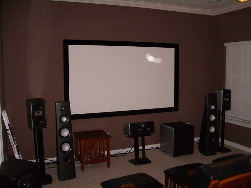
![[Paint]](../../../images/paint_th.jpg/image) We built Reference System 2 in phases, and so we started by hanging the projector screen directly on the back wall (at this point the CinemaSITE was not yet ready for delivery). We quickly realized that painting the room would greatly improve the short-term enjoyment of the home theater, even before it was fully wired up and completed. The end result, however, was that the room needed quite a bit of touching up after completion of the wiring and crown molding installation.
We built Reference System 2 in phases, and so we started by hanging the projector screen directly on the back wall (at this point the CinemaSITE was not yet ready for delivery). We quickly realized that painting the room would greatly improve the short-term enjoyment of the home theater, even before it was fully wired up and completed. The end result, however, was that the room needed quite a bit of touching up after completion of the wiring and crown molding installation.
After you finish the wiring, you'll want to test each cable for continuity and to make sure there are no shorts. There is nothing worse than closing up the job only to finds that a cable does not function correctly or that you impaled a wire with a nail. This is a fairly simple process, but one that could easily be overlooked by those impatient to get on with their room.
Painting the room should be done before you position and introduce any of the final equipment. It takes only a few hours for a couple of inexperienced people to do a medium sized room. We recommend a medium dark color that is not dramatically saturated. You do not want to colorize the picture on the projection screen, so avoid reds, blues or greens. Gray may be the best neutral color, but it is also extremely boring and will likely be met with some resistance from others in the household (you know who you are!) My favorite choice is the Behr Premium paint color we went with which I will call "ambiguous brown". This color is so vague I haven't found anyone who could adequately name it - and that works for me. It has hints of red, brown and burgundy with a neutral overtone. This paint color, or at least one very similar to it, will follow me to my grave and be in any theater room I construct. Use a completely flat paint. You do not want any shiny or reflective surfaces - at least not with a front projection system. I have also found that you get more mileage out of higher quality paints. The cheaper stuff is just watered down and you will likely end up using twice as much. Save yourself some time and spend a little extra up front.
Once we finished painting (or touching up in our case) we were able to caulk the crown molding to eliminate any seams or gaps. We then painted it white to match the trim found in the rest of our home. To be honest, the end result made us want to put crown molding throughout the entire house. It's a nice look and really helps to finish off a room.
Mounting the Projector
![[projectorLG]](../../../images/projectorlg.jpg) Projector mounts are quite possibly the most overpriced, underperforming products in the AV market today. I will even include esoteric audio cables in that statement. For example, this name brand projector mount costs over $350. It is essentially a couple of pieces of bent aluminum and some bolts. You would think, for this amount of money, that the projector mount would include basic cable management - or some method of running thicker cables through the pipe so as to hide their presence. You would also assume that the unit would come with the necessary mounting hardware to secure it to typical ceiling joists (it is a ceiling mount, after all). It doesn't… and what's more, neither do most of its competitors, though there are definitely less expensive mounts on the market. If you need some installation flexibility or you think you may upgrade, we recommend utilizing a painted C-channel system mounted to your ceiling joists to allow the projector mount to slide along and provide some amount of adjustment. If your projector has horizontal and vertical lens shift then the adjustability of the mount will be less of an issue for you.
Projector mounts are quite possibly the most overpriced, underperforming products in the AV market today. I will even include esoteric audio cables in that statement. For example, this name brand projector mount costs over $350. It is essentially a couple of pieces of bent aluminum and some bolts. You would think, for this amount of money, that the projector mount would include basic cable management - or some method of running thicker cables through the pipe so as to hide their presence. You would also assume that the unit would come with the necessary mounting hardware to secure it to typical ceiling joists (it is a ceiling mount, after all). It doesn't… and what's more, neither do most of its competitors, though there are definitely less expensive mounts on the market. If you need some installation flexibility or you think you may upgrade, we recommend utilizing a painted C-channel system mounted to your ceiling joists to allow the projector mount to slide along and provide some amount of adjustment. If your projector has horizontal and vertical lens shift then the adjustability of the mount will be less of an issue for you.
For this particular system, we used a high ceiling mount so that the projector could hang below the ceiling fan - which we decided to keep in the room. This was a decision we made early on since we were also unable to dedicate a separate AC zone to the room. All in all, the mounting process was simple, just disappointing as the cables remained exposed along the pole and around the base of the mount.
Building a Moderately Priced HT - Loading the Equipment
Once we were finished with the room construction it was time to load in the new equipment (we detailed the gear earlier in this article). The change from temporary system to final system was dramatic to say the least:
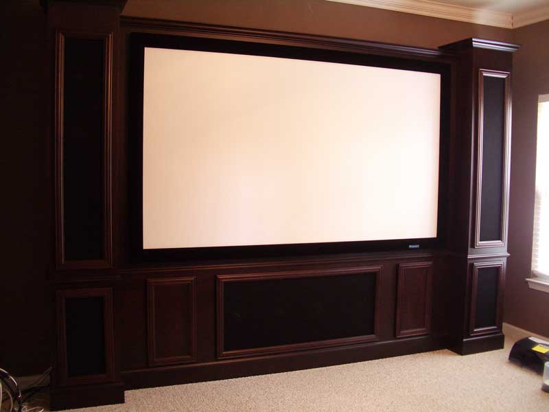
Temporary System Final CinemaSITE System
Check out our first look article of the RBH Sound CinemaSITE system for a full blow-by-blow of that product's integration into Reference System 2. Suffice it to say, the install was amazing, with the main system taking only about 4 hours from unboxing to installation. From there we installed the surrounds and back surrounds and proceeded to load up the equipment rack with our reference equipment.
Room Acoustics
After the room is completed and the equipment is loaded in is a good time to add the room acoustics. You don't want to have absorption panels in the room or Skyline diffusers on the ceiling when you are painting or loading the room. Rives Audio recommended the following products for use in Reference System 2:
- 10) 2' x 2' RPG 7" Skyline diffusers
- 4) 2' x 4' x 2" absorption panels (2" Owens Corning 703)
- 12) 2' x 2' x 2" absorption panels (2" Owens Corning 703)
- 2) Hunter Douglas Duet Honeycomb window treatments
RPG Diffuser Systems provided the absorption panels and the 7" deep Skyline diffusers for this Reference System. When mounting 2" panels 2" off the wall (by using 2x2s or other method) you can achieve significant absorption down towards the 250Hz range. If you merely mount 2" panels on the wall you only achieve meaningful absorption extending down to around 500Hz. Panels less than 2" are pretty much not recommended and won't do much more than provide wall accents or EQ your room's midrange.
We selected RPG's Absorbor™ panels with the Guilford of Maine upgraded fabric and beveled edge. The RPG absorption panels are incredibly easy to install - unbelievably so. Each set of panels comes with a set of three metal spike plates which fasten to the wall (or in the case of this system, the wall-mounted 2x2's) via a couple of screws. After securing the mounting plates, you simply slide the panels downward so that the spikes dig into the fiberglass backing, locking them into place. If you need to reposition the panels, simply pull them up and off and try again.
The RPG Skyline Diffusers are a bit different in that they come with hook and loop fasteners. Since they mount directly overhead at key areas around the room I was hesitant to trust the hook and loops without any additional help. After evaluating my options I opted to screw in the ceiling side of the hook and loops as well as add a "dab" of liquid nails to the center of each 2' x 2' Skyline. There is no way they were going to come down with this type of mounting configuration.
Conclusion
The end result of this room was a pleasing system with a much-improved frequency response and excellent usability. Not only did we end up with an impressive home theater system with hidden equipment and an RF remote - but I am now able to simultaneously evaluate equipment and write reviews in the same room. The CinemaSITE is a spectacle to see - especially in a room that is properly darkened and treated. The fact that about 750+ feet of cabling can be hidden behind crown molding and stealthily dropped down the insidesof walls without exposure is really a sight to... not see.
Where are the listening tests? All over. While we're saving a specific measurement breakdown for another article to coincide with the establishment of a more systematic standard for in-room before and after measurements, all product reviews posted after March of 2006 include the acoustical treatments and finished EQ and subwoofer adjustments of Reference System 2.
Building a reference home theater is no small task and both Gene and I have toiled at it for quite some time this year. Gene, in fact, is still in the process of constructing his premier system. If you take your time, evaluate the options and really plan out your project, you can arrive at a home theater that rivals many of the underperforming screening rooms found in many cities. Hey, maybe that should be the way you pitch it to your significant other?
Clint Deboer was terminated from Audioholics for misconduct on April 4th, 2014. He no longer represents Audioholics in any fashion.
View full profile