
Crimping & Soldering - Keys to Connection Performance and Longevity
RAM Electronics Speaker Cable
Audio and Video Cables are not just dependent on the wire or cable used, or the connectors used. The quality of the connection between the wire or cable and connector is just as important, if not more so. While many inexperienced engineers will commonly overlook longevity concerns and focus solely on initial measurement concerns, knowledgeable engineers always design based on failure rates over time. The biggest problem with the audio/video cable market is that marketing departments choose fads and fallacies, non-applicable specifications and pseudo science over real world objective measurements and tried and true methods of creating wire and cable assemblies that will last for many years with high quality results.
Today we're going to look at those unsung heroes of our A/V world, the ones that hold it all together - the crimp and the solder joints.
Crimping
 Crimping
was invented by Amp Incorporated in 1941 as a solderless method for terminating
wires and connectors. Crimping technologies enabled far more rapid and
consistent wire terminations compared to soldering. Over the years many
different methods of crimping technology were invented for single wires,
multiple wires and coaxial cables. While most people assume a "crimp"
is just a contact crushed onto a wire, giving electrical conductivity by means
of pressure, real crimping involves "elastic" and "plastic"
deformation and flow of metals resulting in "micro cold welds" due to
"contact asperity welding" of the metal surfaces. During the
deformation process the wire and connector are mechanically cleaned, usually
making pre-cleaning of wire and terminal unnecessary. When done right, this
crimped connection can be much stronger and longer lasting than a soldered
connection, and have electrical resistance of the equivalent length of wire. A
properly done crimp is also gas-tight as well, not allowing oxidation to
degrade it over time.
Crimping
was invented by Amp Incorporated in 1941 as a solderless method for terminating
wires and connectors. Crimping technologies enabled far more rapid and
consistent wire terminations compared to soldering. Over the years many
different methods of crimping technology were invented for single wires,
multiple wires and coaxial cables. While most people assume a "crimp"
is just a contact crushed onto a wire, giving electrical conductivity by means
of pressure, real crimping involves "elastic" and "plastic"
deformation and flow of metals resulting in "micro cold welds" due to
"contact asperity welding" of the metal surfaces. During the
deformation process the wire and connector are mechanically cleaned, usually
making pre-cleaning of wire and terminal unnecessary. When done right, this
crimped connection can be much stronger and longer lasting than a soldered
connection, and have electrical resistance of the equivalent length of wire. A
properly done crimp is also gas-tight as well, not allowing oxidation to
degrade it over time.
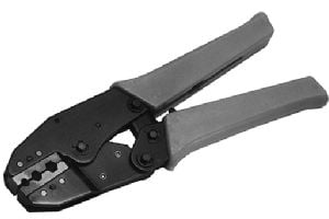
How to make Good Crimps
There are certain critical factors in crimping that are necessary to create a proper cold welded crimp, ideal connector to wire interaction and insulation material support. Properly accomplishing all of these will result in an extremely high electrically performing and long lasting termination with great durability in harsh environments. Perhaps the first thing to understand is that all connectors are made to work with a somewhat small range of wire sizes. Using improperly sized wires and connectors will result in poor electrical performance, poor mechanical strength and often a poor or non existent cold welding of materials. Besides matching the connector with the wire or cable, the proper tooling in the proper condition is also absolutely necessary for a proper crimp termination. The wire, the contact and the tooling are all engineered to very exacting degrees. In the field, crimped contact measurements must be measured to be accurate to very small tolerances, typically within plus or minus a couple of thousandths of an inch or less. The crimps must also be viewed through magnification to be sure that tooling wear or contamination do not adversely effect the quality of the crimp termination. Small amounts of wear or contamination on the crimp dies can result in a poorly formed crimp. Due to the wide variety of crimp types, different methods of field tests are necessary to make sure the proper amount of material displacement is achieved during the crimping process. Some terminals will be crimped and then a "crimp height" will be taken. The crimp height for a terminal will differ with the different wire sizes that the terminal is engineered for. The crimp height is specified by the manufacturer of the terminal and tooling. Manufacturers commonly offer several sizes of a type of terminal to fit different wire conductor sizes. The tooling for these different contact sizes is different as well. While there is most often a "modular" approach to the crimping "applicators" especially for automatic or semi automatic machinery the actual "die sets" for different sized contacts are of a unique size and shape by necessity of the contacts design and wire size compatibility.
Aside from measuring the specified final geometry of the crimped contact, there are other ways to determine if a crimped termination meets certain quality levels.
 A
"Pull Test" is a very commonly used method of determining the quality
of a crimp. It is basically a measurement of how many pounds (or kilograms) it
takes to "pull" the wire out of the termination. With common wire
sizes, this should be as close as possible to the weight necessary to break the
wire itself when pulling on it. Why? The best possible mechanical strength of a
well designed crimped termination just happens to fall very close to the
"sweet spot" of electrical performance. So if you're within range of
the best mechanical strength, you are also within range of the best possible
electrical performance. Crimping just a bit tighter trying to reach the best
possible electrical performance will give only marginally better electrical
performance, but will rapidly over-harden the crimp resulting in
fragility. A pull test should always be
done when there is any question of crimp quality, or when certain types of
termination tooling are set up, such as coaxial cable termination tools. While,
in general, every Manufacturer specifies the proper pull test for various wire
sizes, they do not usually spec them out for every contact, tooling and wire
size combination.
A
"Pull Test" is a very commonly used method of determining the quality
of a crimp. It is basically a measurement of how many pounds (or kilograms) it
takes to "pull" the wire out of the termination. With common wire
sizes, this should be as close as possible to the weight necessary to break the
wire itself when pulling on it. Why? The best possible mechanical strength of a
well designed crimped termination just happens to fall very close to the
"sweet spot" of electrical performance. So if you're within range of
the best mechanical strength, you are also within range of the best possible
electrical performance. Crimping just a bit tighter trying to reach the best
possible electrical performance will give only marginally better electrical
performance, but will rapidly over-harden the crimp resulting in
fragility. A pull test should always be
done when there is any question of crimp quality, or when certain types of
termination tooling are set up, such as coaxial cable termination tools. While,
in general, every Manufacturer specifies the proper pull test for various wire
sizes, they do not usually spec them out for every contact, tooling and wire
size combination.
A very important factor in passing or failing a pull test is where exactly the wire breaks. If the wire breaks within the terminal, it is not usually a good indication. This will usually mean an over crimp, weakening the crimp from too much cross sectional area reduction and "work hardening". If it breaks right where the wire meets the terminal, that may or may not be a bad indication as well. Terminals have what is called a "bell mouth" where the wire enters the terminal. The bell mouth is a flared out area to eliminate cutting into the wires which would happen with an abrupt ending of the crimped area.
When the wire itself breaks outside of the terminal it is generally considered ideal. If the wire is pulled from the terminal without breakage, it is important it only does so within the rated specifications of the terminal or general crimp specifications.
Coaxial Cable crimps generally pull out and do not reach the level of breaking the braided shield material during pull tests. It is important to be sure that coax crimps meet the manufacturer’s specifications on inside and outside conductors in order to be sure of the best possible crimp. Using improper tooling is very easy to do with coaxial cables when substituting brands of cable which may have largely different braid and other shield sizes even within the same cable type designation, such as "RG6".
Other types of crimps have other necessary measurements to determine if the crimping machine and tooling are properly set. For instance IDC (Insulation Displacement Crimp) connector crimps are measured by checking the insertion depth of the wire conductor into the IDC connector using a Dial Indicator. For all types of crimps it is necessary to gauge if the crimp is within specifications to be sure of a proper cold weld and gas tight crimp.
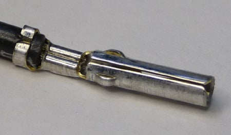
An important and often overlooked feature of most kinds of crimps is the insulation support crimp. This part of the crimp does not contact the wire conductor at all. The Insulation crimp is there to provide strain relief and vibration resistance for the wire crimp. Without a strain relief, or with a poor strain relief crimp, vibration of or repeated flexing of the wires will directly effect the wire barrel crimp and will eventually result in breakage.
Because of speed, cost and repeatability, Crimping is by far the most common type of wire connection used today in electronics. Proper crimping creates a weld between wire and contact, resulting in an extremely reliable, long lasting connection which is extremely resistant to environmental harm.
Soldering
 Soldering
is a method of connecting a wire and terminal using a conductive melted metal
alloy. The filler material is melted and flowed into and around the gap between
the wire and terminal. Upon cooling, the wire and contact are joined in what is
called a solder joint. While not as strong as the wire or contact metals the
solder joint is mechanically strong. The alloy material used in soldering is
chosen for its low melting point and good electrical conductivity. Historically
a mixture of about 63% tin and 37% lead was used for its extremely low melting
point. While solder with lead is still often used in mission critical
applications like aerospace and medical, it is being replaced today with lead
free solder which most commonly uses a Tin, Silver and Copper alloy.
Soldering
is a method of connecting a wire and terminal using a conductive melted metal
alloy. The filler material is melted and flowed into and around the gap between
the wire and terminal. Upon cooling, the wire and contact are joined in what is
called a solder joint. While not as strong as the wire or contact metals the
solder joint is mechanically strong. The alloy material used in soldering is
chosen for its low melting point and good electrical conductivity. Historically
a mixture of about 63% tin and 37% lead was used for its extremely low melting
point. While solder with lead is still often used in mission critical
applications like aerospace and medical, it is being replaced today with lead
free solder which most commonly uses a Tin, Silver and Copper alloy.
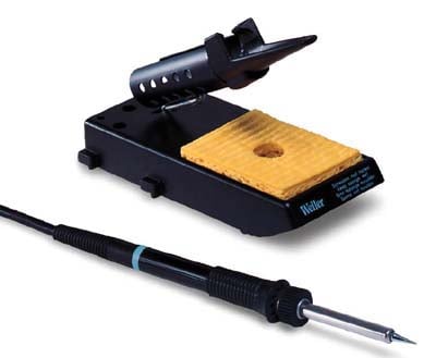
Several factors are involved in creating the best possible solder joint. You need to start with clean, non-corroded materials and a soldering iron at the proper temperature for the solder with a clean tip of proper size and shape for the wire and contact to be soldered. The wire and contact to be soldered must be prepared by tinning and shaping the wire or mechanically pre attaching the wire to the terminal before soldering. Properly doing all of this sounds pretty basic and easy, but it's not. Associations like the IPC (Institute for Interconnecting and Packaging Electronic Circuits) or WHMA (Wire Harness Manufacturers Association) have created standards which designate the proper ways to create the best possible solder connections of many varieties. For solder connections to meet standards like IPC/WHMA - A 620, they must meet certain criteria with regards to insulation clearance, proper mechanical attachment, proper tinning, wire routing, cleanliness and appearance.
How to make a good solder Joint
The first step in soldering is cleaning, if necessary. Flux - a chemical cleaning agent is used, when necessary, to remove oxidation from the wire and terminal and protect them prior to soldering. Flux can be in liquid or paste form and, in fact, is included in solders made for hand soldering. There are numerous different types of flux, which may or may not have to be removed after soldering. Often there is enough flux in the solder to eliminate the need for additional flux.
The next step is tinning the wire and terminal. Care must be taken not to melt or damage the insulation. The idea is not to cover the wire with solder, it is to let solder flow onto and into the wire via "wetting" and "capillary action". These same physical and molecular forces are also used to create a proper solder joint during final soldering.
After tinning, the wire is properly formed, if necessary, onto the contact or in a shape that will allow easy attachment to the contact.
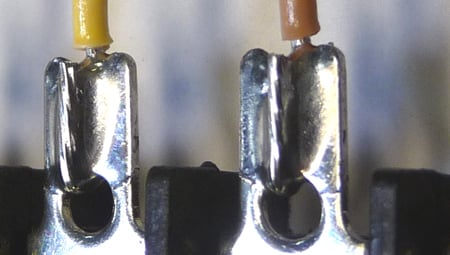
The act of soldering the wire and terminal usually looks very easy, but is practically an art form. First the two parts must be simultaneously heated using the iron to reach the solder melting temperature. Then, the solder is applied to the materials which cause the solder to melt and flow. The solder flows into, onto and around the materials via wetting and capillary action helped along by the flux. No excess solder should be flowed onto the joint. Just enough solder to create the bond between materials. The wire and contact must remain motionless during the soldering process as well as during cooling. If the wire moves during cooling, or the solder is heated solely by the iron but not the wire and terminal, a "cold" solder joint is created. Cold solder joints look dull and gray rather than shiny like polished chrome. While new lead free solder joints don't have the same shiny look as "classic" lead based joints, they should still look smooth and shiny.
After soldering, cleaning is very often necessary. Some fluxes are water soluble and some are not, so you'll need to check your flux and solder for the proper flux cleaner for the type of flux used in pre-cleaning and within the solder.
Soldering is the second most commonly used way of attaching wires and connector contacts. With proper cleaning and soldering techniques an excellently performing connection can be made that will have excellent conductivity and long lasting reliability.
Conclusion
 The quality
of a cable is not in the fanciness of its jacket, the color scheme of its
pretty molded connectors or the cables overall thickness. Common beliefs to the
contrary, the quality does not necessarily lie in the cables gauge, percentage
of silver in the conductors, nor how many carrots the gold plated contacts are
rated at.
The quality
of a cable is not in the fanciness of its jacket, the color scheme of its
pretty molded connectors or the cables overall thickness. Common beliefs to the
contrary, the quality does not necessarily lie in the cables gauge, percentage
of silver in the conductors, nor how many carrots the gold plated contacts are
rated at.
The quality can be seen in the suitability of the specifications of the cable used. The quality can be seen in the quality and suitability of the connection terminals. And the quality can be seen in the point most likely to fail - the solder joint or the crimped connection between those two.
Many thanks to Ram Electronics for allowing us to publish this article.