
Setting the A/V Receiver Impedance Selector Switch
Half Portion
Originally published: Aug 2, 2010
What if you
went to your favorite local restaurant, ordered a meal and the waiter served you 1/2 the portion but charged you
full price? Would you feel cheated? Believe it or not,a good deal of home theater
enthusiasts are spending good money on the latest and greatest A/V receiver
from their favorite manufacturer and serving the same half-portion to their
speakers. I can't tell you how many
times I've run into threads on our forums or on AVS Forum where users either
were utterly confused about how to set the impedance selector switch on their
new A/V receiver or they decided to set it to the low setting because their
speakers were rated below 8-ohms and the user manual said
to do this, or Joe the Plumber set his this way and we all want to be like
Joe. Some even set the switch to the low
setting while still running 8-ohm speakers, thinking it will
be better.
This article explores why the impedance switch exists and its intended
purpose. Because of liability and the
litigious society we live in, I can't tell you to ALWAYS set the impedance
switch to the high setting for 4 ohm loads, but I can show you the facts on
what this switch does along with supportive data for you to make your own
educated decision.
If you call the manufacturer, they will tell you to ALWAYS set the switch to the low setting when using 4-ohm rated speakers mostly due to liability. UL/CSA labs may instruct you similarly. It’s a damned conspiracy! Well, not really. I know it sounds crazy to go against the manufacturer's recommendation, but hear me out before you shoot the messenger.
How Should You Set the Impedance Selector Switch on Your AV Receiver? MUST WATCH!
The Basics
Let's back up a bit and define a few basic terms to gain a better understanding of the topic at hand.
- Voltage – Is electromotive force. This is defined as a potential electrical pressure difference between two points in a circuit measured in volts (V).
- Current - flow of electrons in a circuit measured in amperes
(A).
- AC (Alternating Current) – The electrons move to and fro in the circuit in alternating direction.
- DC (Direct current) – The electrons move in a single direction in the circuit.
- Resistance – The measure which is the inverse of electrical conductance to direct current. This also can be considered as the ratio of electromotive force (Volts) divided by the flow of current (Amperes).
- Impedance – is a complex measurement of opposition to current flow in an (AC) circuit. With AC, or alternating current (alternating at any frequency higher than Zero Hertz, which is Direct Current) impedance can be represented as the complex combination of Resistance (DCR) and Reactance (“Resistance” to AC current flow). AC ”Resistance”, technically called Impedance is a frequency dependent, complex measurement including both a magnitude and phase component. This complex quantity is often represented as the letter “Z”.
- Power - is equal to the product of Current and Voltage times a power factor, resulting from the phase difference (if any) between the flow of the current, and the presence of electromotive force (Volts). This product is measured in watts (W). (In DC circuits, or even AC circuits where the load is purely resistive, the phase is zero, and the power factor is one, so the equation is simple Watts = Volts * Amperes)
What About Loudspeaker Impedance?
Loudspeaker Impedance is often stated as a single rating in ohms. This is done for the sake of simplicity, as few ,if any, real loudspeakers present a constant load to their amplifiers. Typically, the magnitude of the loudspeaker impedance can range from a few ohms to many hundreds of ohms. Loudspeakers are electro-mechanical transducers that operate with AC signal input. They will also operate at DC, but only long enough for the VC to go one direction and jump out of the magnetic gap. As a result, specifying a loudspeaker by its DC impedance or voice coil resistance is a little bit like trying to guess how much horsepower the engine produces based on the number of doors on a car. At and near the resonant frequency of the loudspeaker, its impedance often rises to more than 100 ohms. The nominal impedance is basically a conservative notion of how low the speakers impedance will go over the range of frequencies it is operating over, so that musical spectrum in that range will not cause the amplifier to be overloaded if the amount of current drawn by the loudspeaker is too high. As we can see from the impedance magnitude curves (bold blue) and phase (light blue) for the measurements below, the absolute value of the speaker's Impedance varies enormously, and it is the area on the curve where the magnitude is lowest that poses the greatest current demands on the amplifier. This is especially true when this low flat region corresponds to that range of frequencies where much musical information lies. It is the impedance in this low region that was typically used to define the loudspeakers “nominal” impedance. Based on our definitions above, and measurements below, it's easy to see that a loudspeakers impedance is NOT constant but instead a function of frequency which can also vary drastically from the minimum or “nominal” impedance of the loudspeaker.
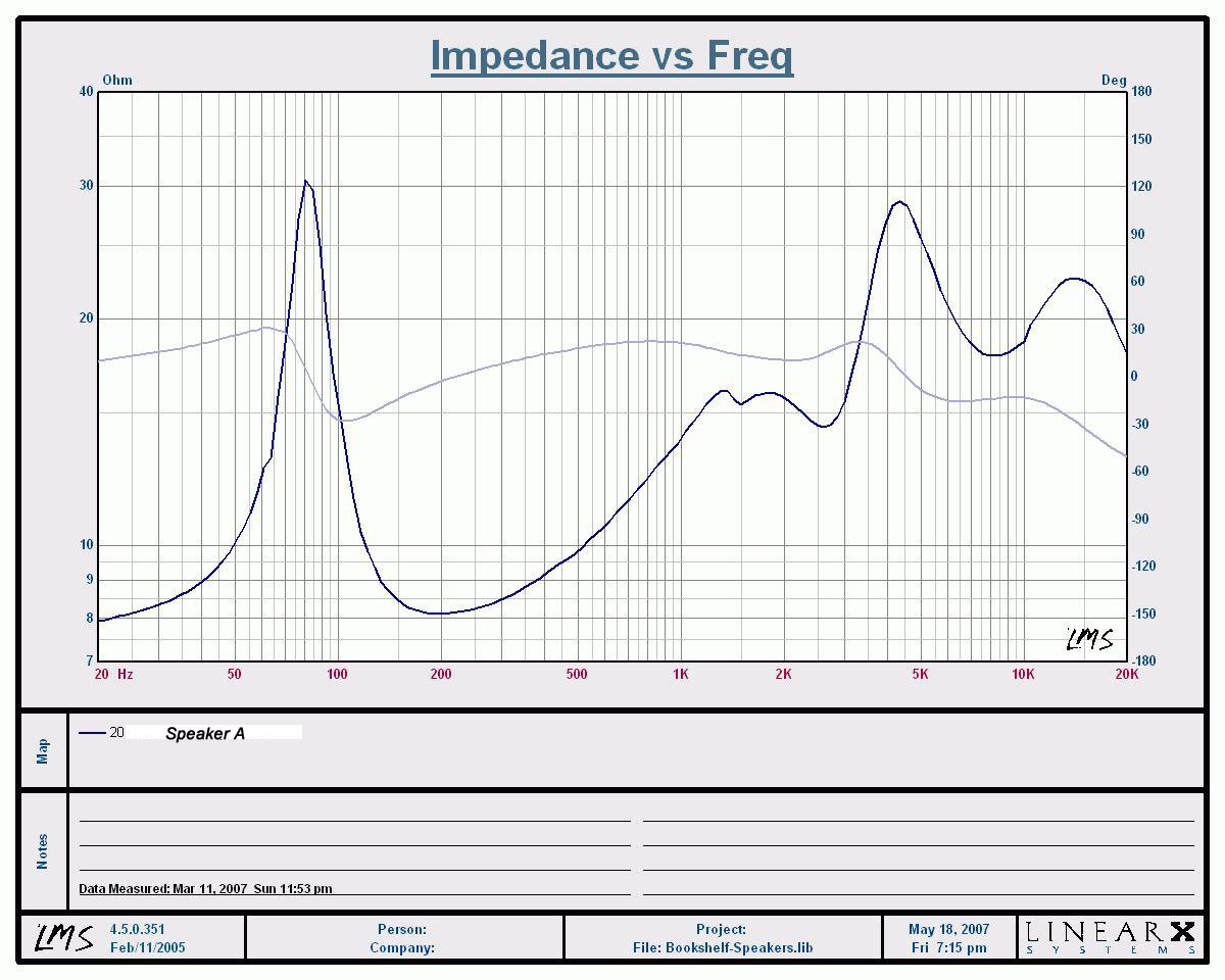
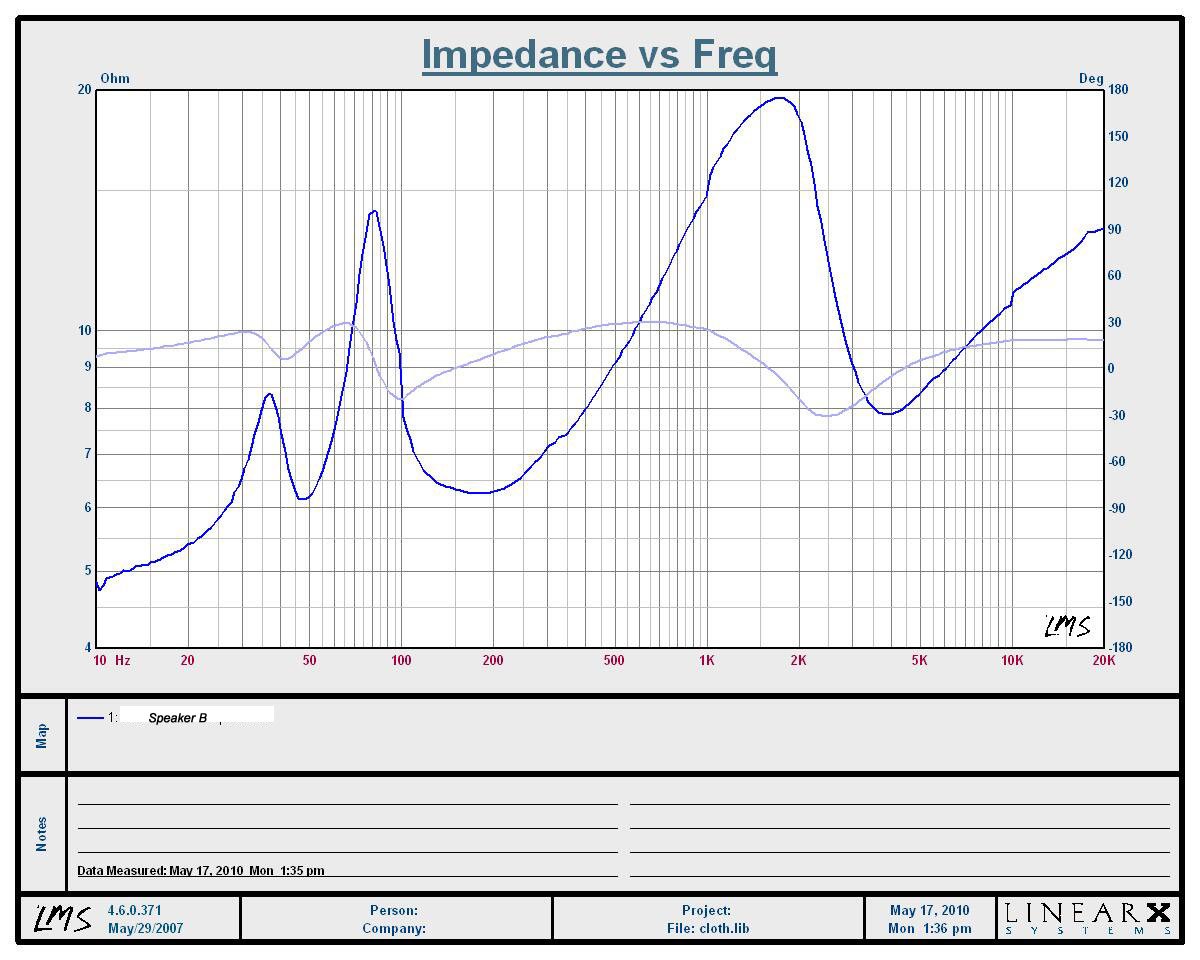
Impedance/Phase of two competing speakers (Left Pic: SPK A; Right Pic: SPK B)
Both of these speakers are rated at 8-ohms by their respective manufacturers. Yet when you look more closely at the curves, they look drastically different not only from each other, but from the straight horizontal line that would represent a purely resistive impedance. You can see Speaker A (left pic) never dips below 8-ohms at any frequency. In this case the manufacturer rated the speaker very conservatively. Speaker B exhibits several dips into the 6-ohm region measuring lower than 5-ohms below 20Hz. This particular loudspeaker lacks a high-pass section for its midrange speaker, so at low frequencies those midrange speakers are in parallel with the woofer, creating a high current demand on the amplifier, which can cause it to shut down. This happened to me personally when this speaker was driven with extremely low frequency content at high output levels using a very beefy Marantz Integrated amplifier rated at 200wpc. Despite the fact that there is little musical content near or below 20Hz, the amplifier still sees that speaker as a dangerous load when driving it. If this system is using a turntable, and if there is a slight warp to the record, the combination of phono cartridge and RIAA equalization curve may be producing a demand for output at 15Hz from the amplifier/loudspeaker combination that could be larger in magnitude than the entire audible musical spectrum! The RIAA curve made for LP's and phono cartridges uses far higher gain at the lowest frequencies than the highest. Those of us not old enough to remember when our music was sold on LP records may have never witnessed this. Suffice it to say, those who favor LP's over digital media must be proud owners of high order subsonic filters as part of their electronic arsenal. The effect of even a modest amount of low frequency energy in the subsonic range can cause the loudspeaker, especially vented designs, to move wildly causing gross distortions under extremely high excursions they were never designed for.
There is no universally adhered-to standard for how consumer loudspeaker manufacturers rate loudspeaker impedance! The EIA published a standard which has for many years been the defacto standard for determining nominal loudspeaker driver impedance. That standard stated the impedance would be measured at 400Hz, and the voice coil resistance should not be below 6.4-ohms for an 8-ohms speaker, or twice that for a 16-ohm speaker. That standard has become less and less common in the business as the race for sales created a pressure for manufacturers to use ever lower DC Resistance's (DCR's) on their voice coils to increase the apparent efficiency by drawing more power (lower impedance loads draw more power than higher impedance ones when attached to amplifiers) than the competition. For equally efficient systems, the 4 ohm speaker should be 3db higher than the 8 ohm speaker having identical efficiency!
Realizing the fact that impedance is a complex and greatly variable quantity, don't get hung up on an absolute number for impedance. It's important to look at the loudspeaker's impedance curve and efficiency to understand how it will play with the amplifier it is coupled with. Impedance dips at low to middle frequencies where much of the power is present in music can be far more stressful on linear class A/B amplifiers than dips in impedance magnitude at high frequencies, where demands for power are relatively small. The opposite is true for Class D amplifiers, some of which choke when presented with low impedance dips at high frequencies because of potential interactions with their output filter.
Amplifier and Power Supply Basics
To gain a better understanding of how amplifiers and their associated power supply work together, we need to do a little math. Don't worry these are simple equations that even Sarah Palin could comprehend, especially since they can fit in the palm of her hand.
P
= V * I (Eq1)
P = V^2 / R (Eq2)
Let's first discuss amplifier DC voltages to better understand the “V” in Eq1. Amplifiers require a DC (sometimes called rail) voltage to provide a constant power source which the amplifier can in turn use to amplify the input signal. Assuming the output devices can source (allow to pass through them) the current to the load, (In this case our loudspeakers) the higher the DC rail voltage, the more potential power output power the amplifier can produce. As long as the input signal increases, if there is available voltage and current from the amplifier, there will be available power to send to the speaker. If not, and the amplifier attempts to increase the signal beyond the fixed boundaries of the rail voltage you get what is known as amplifier clipping. This also happens if the current demand on the power supply exceeds what is available. That too will cause the DC Voltage rails to sink lower than what is normal and cause amplifier clipping. These limitations occur when the power supply is asked to supply more power, as either available voltage or current, than it can make available. If the clipping is caused by drawing too much current, there will be additional distortion components in the output signal (compared to the voltage clipping scenario) as the variations in the rail voltage will be transferred to the speaker load as AC signal content unrelated to the input signal (i.e, distortion). Amplifier clipping is bad because it takes the undistorted waveform and essentially clips off the top and bottom of it. This creates high frequencies not present in the original signal, in a word, distortion. When done to extremes, the original signal can be converted from a sine into a square wave. The square wave includes high frequencies not originally present in the signal, which represent a real hazard to the loudspeakers systems high frequency device(s) voice coil(s). Clipping is therefore especially dangerous to small light and delicate high frequency loudspeaker components in a system as the square wave contains far more high frequency energy than was found in the original music signal. It can take an unclipped musical signal sending 5% of the energy to the tweeter, and suddenly send 25% of the increased power available to the tweeter. Clipping, despite what you have read on the blogs, is rarely damaging to woofers by comparison.
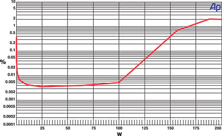
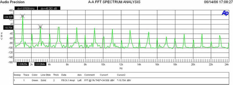
Top Left pic (clipped sinewave) ; Top right pic: amplifier power vs distortion
Bottom Pic: FFT Analysis of Amplifier in Clipping
As you can see in the left image above, the middle peak and dip of the sine wave is clipped or flattened once the rail voltage of the amplifier is exceeded. The pic to the right shows an amplifier power vs distortion measurement I conducted. As the amplifier starts to visibly clip, it approaches 1% THD. This is clearly an audible amount of distortion that can also be seen with an oscilloscope. (The oscilloscope shows us the voltage versus time). If you do an FFT analysis of the spectrum (showing us the frequency components in the time signal displayed by an oscilloscope), you can see all of the nasty harmonic byproducts (Multiples of the original frequency or harmonics for short) that are added to the original 1kHz fundamental. This system is producing severe distortion due to clipping. This not only sounds bad, but it's bad for the speakers too.
If a receiver's power supply has sufficient current supplying capacity, and the amplifiers output impedance is low enough, then it can operate fairly closely to an ideal voltage source doubling available output power as the load impedance halves and the voltage output remains the same. (see Eq2) (Remember, in a good amp the same voltage is present at the loudspeaker terminals for an 8 ohm, 4 ohm, or a 1,000,000 ohm loudspeaker is present, and is dependant on the signal input amplitude and gain of the amplifier., and NOT the load attached) So when a 100 Watt per channel receiver is driving an 8-ohm load, it delivers 28.3Vrms. (28.32/8 = 100) which into a 4-ohm resistive load would produce 200 watts. (23.82/4 = 200) Most receivers don't operate so ideally however, so while they all will try to deliver more power into a lower impedance, they may first run out of voltage, or worse yet, available current. This lack of available current will cause the voltage rails to shrink, clipping the signal, and thus generating more heat as losses in the process.
Since transformers and output devices have a finite amount of resistance, those losses will occur as I2*R, amperes squared divided by resistance. Transformer windings and output devices do not have fixed resistances either. As they are burdened with greater and greater current demands, this heating causes their resistance to increase. Eventually, the system either reaches a static operating temperature or it simply burns up. While loading an amplifier with a lower impedance loudspeaker load is not universally dangerous it does put an extraordinary load on the power supply components, which can overheat if this demand continues for extended periods of time. More on this later.
Editorial Note About the Cost of Power Transformers
If size and cost and weight were not an issue, manufacturers could supply receivers with their own power station, and then the limiting factor would be the output devices and heat sink. The cost of steel and copper from China has varied dramatically over the last few years, and manufacturers do not want to see their costs suddenly skyrocket or their supply dry up because they negotiated a low price that causes the vendor to lose money when the cost of materials used skyrockets! This is perhaps the most expensive part of the entire amplifier! (Except of course for marketing)
What Does the Impedance Selector Switch Do?
 It parts the red sea, stops the BP oil leak and reduces our carbon
footprint. It would be easy to draw
these conclusions if you spend enough time reading the misinformed consumer
comments in the forums on this very topic.
If this was in fact true Obama would have already been taking credit for
such a marvelous invention.
It parts the red sea, stops the BP oil leak and reduces our carbon
footprint. It would be easy to draw
these conclusions if you spend enough time reading the misinformed consumer
comments in the forums on this very topic.
If this was in fact true Obama would have already been taking credit for
such a marvelous invention.
Let's examine some power measurements of receivers I measured in the past that featured impedance selector switches to deduce exactly what they are doing. The receivers range in price from $500 all the way up to $5,500.
Low Impedance (Z) Mode - is the receivers "low" setting that the manufacturer recommends using when you attach loudspeakers rated below 8-ohms. (This mode limits the output voltage, and therefore the maximum current any given speaker can demand of it).
High
Impedance (Z) Mode - is the
receivers "high" setting that the manufacturer recommends using when
you attach loudspeakers rated at 6-ohms or higher. This is usually the
default setting the receiver ships in, and the rating which the manufacturer
optimizes his parts for, since they only have to advertise ONE power rating
before the consumer will reach for his checkbook or credit card.
PLoss - Power Loss (%) determined by comparing the Low Z and High Z power
numbers for each receiver using the following equation: (1 - LowZ / HighZ) *
100
|
Manufacturer |
Model |
Load |
High Z |
Low Z |
Ploss |
THD |
|
Yamaha |
RX-Z11 |
8-ohms |
190 watts |
190 watts |
0% |
0.10% |
|
|
4-ohms |
300 watts |
300 watts |
0% |
0.10% |
|
|
Yamaha |
RX-Z7 |
8-ohms |
170 watts |
78 watts |
54% |
0.10% |
|
|
4-ohms |
255 watts |
144 watts |
44% |
0.10% |
|
|
Yamaha |
RX-V4600 |
8-ohms |
134 watts |
95 watts |
29% |
0.10% |
|
|
4-ohms |
210 watts |
180 watts |
14% |
0.10% |
|
|
Yamaha |
RX-V2700 |
8-ohms |
144 watts |
78 watts |
46% |
0.10% |
|
|
4-ohms |
272 watts |
144 watts |
47% |
0.10% |
|
|
Yamaha |
RX-V661 |
4-ohms |
224 watts |
63 watts |
60% |
1% |
|
Onkyo |
TX-NR5007 |
8-ohms |
191 watts |
Not tested |
1% |
|
|
|
4-ohms |
171 watts |
68 watts |
72% |
1% |
|
Note: All tests were conducted with one channel driven at 0.1% THD + N using a 1kHz test frequency except the 1% THD tests which were conducted by Sound & Vision Magazine.
As you can see in the tabulated data above, 5 of the 6 receivers exhibited significantly less output power when their switches were set in the "low impedance" mode for both 8 and 4-ohm loads. In fact the lowest priced Yamaha (RX-V661) and Onkyo (TK-NR5007) models exhibited the most power scaling in the low impedance mode (72% reduction, 60% reduction, respectively) The RX-V2700 power derating of the low impedance mode was interesting in that it maintained their specified 8-ohm output power rating of 140 watts into a 4-ohm load. I find it noteworthy that the Yamaha RX-Z11 power output did NOT change based on the impedance switch setting. It's obvious in this case that the designers of this receiver were confident no derating was needed to pass the regulatory testing. This isn't surprising giving the sheer size and expense of this engineering marvel, hence why they call it their flagship model!
What the "low impedance" setting accomplished (except for the Yamaha RX-Z11) was to step down the rail voltage fed to the amplifier by the secondary of the power transformer. The unfortunate side effect was clipping at a much lower power level as seen in the tabulated test results. The low switch setting appears to limit the maximum available current draw on the transformer to about 1/3rd (Onkyo TX-NR5007) as much as the high setting so that it would be able to play continuously (at a significantly reduced power level) during the UL/CSA certification testing while generating significantly less heat.
There is no set derating number that manufacturers use as far as I can tell. I surmise that they calculate the maximum power their receiver can deliver at a certain distortion level while still maintaining a low enough temperature so that it will pass UL / CSA certification, deeming it safe to operate into 4-ohm loads. This value depends greatly on how well the amplifier can dissipate heat which is a function of heatsink area and ventilation and also the VA rating (Volts time Amperes) of the power transformer and how much actual power the amplifier can deliver before failing. Realize that the power transformer is wrapped up tight and into a ball. In most cases, manufacturers don't heat sink them but some do add a cooling fan which turns on during high current demands to cool off the power supply. They do put resettable fuses and heat sensing switches inside to prevent them from burning the enamel off the windings. The "low" setting of the switch is providing some protection to the power transformer from blowing up under a continuous maximum power condition into 4-ohm loads, but so is the overload protection circuitry that causes the receiver to shut down if driven into clipping for more than a few seconds in either impedance mode. The low impedance setting is also killing amplifier headroom and maximum available power which will send more distorted and clipped signals to your loudspeakers.
But where are the Failures?
It's equally important to reiterate that most receivers have overdrive protection built in independent of this impedance switch so if the power supply is stressed into exceeding maximum rated power, or full rated power simultaneously into multiple channels, the power gets scaled back significantly or the receiver shuts down. This can be seen in some models during All Channels Driven (ACD) tests where a limiter kicks in and cuts power down to 1/4 or less rated one channel power. I've never blown out a receiver during my power torture tests, but I have shut many down when driven hard into 4-ohm loads in both the low and high impedance settings.
In speaking with Yamaha, they told me they could not confirm any failures of receivers directly attributed to running the high impedance mode with 4 ohm speakers. Their power supply / amplifier failure rate hasn't changed with the inclusion of the impedance selector switch on their A/V receivers. One has to wonder, just how much over-protection does the user need until it starts compromising real world dynamics and headroom while using the product with musical program material and not continuous test tones in a lab environment? Is it worth potentially damaging your speakers to protect your receiver? I guess that’s a philosophical question depending on which is more valuable to you.
What is UL / CSA Actually Testing?
Let's first define what UL and CSA stand for.
UL (Underwriters Laboratories, Inc) - is an independent organization that develops product safety standards with a diverse group of individuals representing government, consumer, manufacturer, electrical inspection, supply chain, and general interests. UL provides national safety certification of products to these standards and global certification using country specific standards following a successful evaluation consisting of product construction and testing.
CSA (Canadian Standards Association) - is an independent certification organization that serves business, industry, government and consumers in Canada and the global marketplace. In addition to certification testing, they also develop standards that enhance public safety.
When consumer A/V gear gets certified by either UL or CSA, it is done so in accordance with the U.S. or Canadian national standard for safety, UL 60065 or CAN/CSA C22.2 No. 60065, respectively. These Standards are harmonized with the International Standard for Safety, IEC 60065. I decided to phone UL to ask them exactly what is being tested on A/V receivers and amplifiers per these standards and how it relates to power and heat dissipation.
The short story is the product (or as they refer to it: the A/V apparatus) is evaluated (including testing) to reduce the risk of user injury and ensure protection of property as a result of:
-
fire hazard;
-
electrical shock hazard;
-
hazardous radiation emission including laser, x-radiation, UV;
-
mechanical hazards – including implosion of CRTs, apparatus instability;
-
heating under abnormal operating conditions and simulated single fault conditions;
-
heating under normal operation
The last bullet about heating under normal operation is the crux of this article.
How Does UL Measure Power?
The UL engineer I spoke with told me that the subject of heating under normal operating conditions continues to be discussed as the testing methods have essentially remained unchanged since the time of one and two channel, Class A and AB amplifiers with linear power supplies. UL, CSA and International A/V Standards have established 1/8 unclipped output power, all channels driven into rated load as representative of normal operating conditions. In the old days they used to simply feed a 1 kHz sine wave tone into one of the amplifiers channels when connected to a fixed impedance test load and Oscilloscope across the speaker terminals and ramp the gain up until clipping was visually observed. The resolution of an Oscilloscope is about 20dB or 1% THD.
As best as I can tell, UL/CSA test 4-ohm loads as specified to be used with the product by the manufacturer. There is a test process by which they determine how they will load an amplifier to simulate normal operating conditions. We have already discussed the determination of non-clipped audio output power. Determination of non-clipped output power forms part of what they refer to as a Power Input Test. The results of this test serve to provide data from which they can make a determination of the test set-up for their normal temperature test. During their Input Test, UL will operate the amplifier under all output loading conditions as specified in the user manual (i.e. 8-ohms for all channels, or 4-ohms for the front channels, 8-ohms for the other channels) and/or marking on the rear panel. This can include operation of the front main L/R channels while connected to 4 or 8-ohm simulated speaker loads with the impedance selector switch (if any) at its recommended setting. As discussed, a sinusoidal input signal (1000 Hz in the case of a "full frequency range" audio amplifier) is provided to drive the front main L/R channels loaded as previously described. From the voltage measured across the simulated load, the non-clipped output power is calculated. If the configuration of the amplifier is such that the non-clipped power determination of the mains L/R channels cannot represent the remaining channels, this process is repeated. Armed with non-clipped power output data (voltage and resistance), they then calculate 1/8 power and make a set of input power measurements with ACD at 1/8 power into all combinations of simulated speaker loading. The input current and power are monitored under each loading condition. UL's decision for the test configuration/set-up of the heating under normal operation test -- including speaker loading -- is based upon consideration of maximum non-clipped output power, input current, and input wattage. They make every effort to determine (based upon these values) a single test set-up condition that will be a "worst-case" representation. If this is not possible, the normal heating test under normal operating conditions test is performed multiple times, under varying simulated speaker loading conditions. The bottom line is, UL does use a process (Input Test) to make a determination of amplifier power output and simulated speaker loading conditions used to establish normal operating conditions.
Editorial Note on Specified Test Signal of 60065
Back in the "old days" UL used a sine wave signal input for both maximum power determination and normal temperature testing. Today, the 60065 Standard permits the use of either the "standard signal" [band limited pink noise] or a sine wave [1000 Hz or geometric mean frequency] to be used as a signal source for testing. The Standard further states that if testing with the sine wave does not comply with the standard,test results with the standard signal are considered decisive.
So, if a receiver measured 100 watts into 8-ohms unclipped (<1% THD), they would drive all channels at 12.5 watts into 8-ohms continuously while monitoring temperature rise using thermocouples. In addition to monitoring the temperature of internal components, wiring, and mechanical parts, a safety laboratory would evaluate steady state temperature rises of accessible parts to ensure that:
-
accessible, graspable (e.g., handles, knobs) metallic parts do not rise more than 30 deg C;
-
accessible, graspable non-metallic parts do not rise more than 50 deg C;
-
parts of metallic enclosures do not rise more than 40 deg C (except the UL Standard specifies that parts not likely to be touched during intended use, i.e. heatsinks may rise not more than 65 deg C when provided with a hot surface marking);
-
parts of non-metallic enclosures do not rise more than 60 deg C;
-
critical electrical insulation temperatures do not exceed prescribed maximums.
Note: UL uses an ambient room temperature of 35 deg C (95 degrees F) unless the equipment is rated for use in tropical climates, i.e. 45 deg C, in which case the permissible temperature rise is decreased by 10 deg C. That’s one hot room!
So what is happening when the impedance switch is flipped to the low setting is that it's bringing the baseline power level down proportionally to what the manufacturer thinks is safe enough to pass UL/CSA heat dissipation tests. Since the manufacturer doesn't specify how much power the product is rated to deliver into 4-ohm loads, it can now tell UL or CSA what power level to test to and de-rate accordingly. Let's take the Yamaha RX-V2700 as example and run some power numbers based on the 1/8th UL/CSA heating tests to see what is happening.
|
Manufacturer |
Model |
Load |
High Z |
Low Z |
|
Yamaha |
RX-V2700 |
8-ohms |
144 watts |
78 watts |
|
|
4-ohms |
272 watts |
144 watts |
|
For High Z:
Front Two
Channels (4-ohm
load): => 1/8*(272) * 2 = 68 watts /
(0.5) (estimated efficiency) = 136 watts
Remaining 5
channels (8-ohm load):
=> 1/8*(144)*5 = 90 watts / (0.5) = 180 watts
Total Power
dissipation = 136 watts + 180 watts = 316 watts
For Low Z:
Front Two
Channels (4-ohm
load): => 1/8*(144) * 2 = 36 watts /
(0.5) (estimated efficiency) = 72 watts
Remaining 5
channels (8-ohm load):
=> 1/8*(78)*5 = 49 watts / (0.5) = 98 watts
Total Power
dissipation = 72 watts + 98 watts = 170 watts
Note: the power dissipation calculations only factor in amplifier power consumption so you can expect another 25-50 watts of power dissipation for processing and preamp functions.
As you can see the Yamaha RX-V2700's power consumption for this test is now less than 50% less for the low impedance mode and hence the receiver is dissipating 50% ore less heat during the UL or CSA test certification process.
Editorial Note About Transformers & Power Limiting:
The impedance switch doesn't guarantee 1/2 power as you can see in the variable measurements of the above four receivers we tested. It really depends on the transformer VA rating and what load impedance it was optimized to drive. IF you have a small transformer, and IF the predominant heat was I^2 * R losses in the primary and secondary, then you get a transformer which is less efficient at higher currents which has to be accounted for in the design. IF you have a transformer with not enough steel, and the higher voltages cause the waveform to clip because of the voltage creating saturation in the core (usually it is excess current and high voltage together doing this), the wire size will have to be changed on the transformer to avoid this problem. If the transformer has to work on both 4 and 8-ohms, it will likely work best on a 6-ohm load OR be optimized for one, and the other is an afterthought. It is this action being taken by the manufacturers which are playing "specsmanship" with the numbers instead of making the best engineering compromise and publishing both sets of numbers (power into 8 AND 4-ohm loads) for their customers. Until we as consumers demand more complete information from amplifier manufacturers, they will count on our ignorance and optimize their amplifiers for one load (8-ohms for example) and by virtue of the cost/performance analysis decide that the lower power setting needed to secure UL/CSA certification won't preclude their selling the products if the consumer is never going to ask the question, "and what about power into a 4-ohm load?".
Why Do Some Receivers NOT Have the Impedance Selector Switch?
There are three reasons actually, with one being the most common with respect to consumer A/V gear as we discuss below:
-
The receiver in question has a large enough power transformer, output devices and heatsink area to properly dissipate heat under full 4-ohm power tests (very uncommon, I can count the number of multi channel A/V receivers on one hand that do and still have fingers left over)
-
The receiver is NOT rated for 4-ohm loads at all (most common)
-
The receiver was actually designed for a low impedance load, (like in the Professional Audio arena) and the user is willing to accept a lower available power number into the high impedance load than he is going to see advertised for the minimum impedance it can drive. This is the standard in the Pro Audio business as can be seen in the QSC data table below which was taken from this link.
QSC CX 2-channel Amplifiers
Watts per channel
Model 70 V* 8Ω** 4Ω** 2Ω†
CX302 − 200 325 600
CX502 − 300 500 800
CX702 − 425 700 1200
CX902 440 550 900 1500
CX1102 1000 700 1100 1700
CX302V 250 − − −
CX602V 440 550 − −
CX1202V
1000 700 1100
−
*1
kHz, 0.05% THD**20 Hz – 20 kHz, 0.05% THD †1 kHz, 1% THD
Note: 70 Volt
applications are for commercial distributed systems like malls or supermarkets
Let's now explore the most common reason in consumer A/V regarding the lack of impedance switches on many of the A/V receivers on the market today.
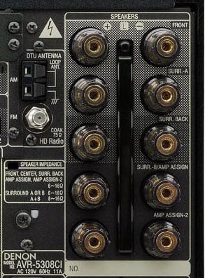
Yamaha RX-Z7 (left); Denon AVR-5308CI (right)
The Yamaha RX-Z7 receiver has an internal impedance selector switch while the Denon AVR-5308CI receiver does not. Can you guess which receiver has a 4-ohm rating for its speaker terminals?
If you guessed the Yamaha, then you guessed correctly. Despite both receivers being similarly sized and having the same power rating, the Yamaha is the only one with the 4-ohm marking on the back panel. If you look closer, there are two caveats to this rating:
-
the receivers impedance selector switch must be set to the low setting
-
the 4-ohm rating is only applicable to the two front channels
So What Should I Do?
The wisest thing to do is to be prepared to ask the right
questions when shopping for your AV receiver prior to your visit to the store.
Read reviews from reputable review publications that test and measure amplifier
receiver power into 8 and 4-ohm loads. Know if your speakers, the ones you own, or
the ones you intend to buy for use with this receiver are rated at 8-ohms or 4-ohms, or something
else. If your preferred speakers are 4-ohms, or a highly reactive load, you may well do better
off with a separate power amplifier with a well-built hefty power supply. If economics prevent you from choosing that
option, find a review that actually measured the speakers you plan to use. As we know from the impedance magnitude graphs previously shown here,
using a simple number to identify them is not a reliable method, and in some
cases, nearly useless. Even when the
speaker is rated at 4 or 8-ohms, without an
actual measurement we have little idea of how it can or will behave with any
given amplifier or receiver. A load
which changes rapidly with frequency is also a difficult load to drive. Having a large phase angle means the
amplifier has to deliver current before or after the voltage changes. That is a difficult thing to do with any
amplifier, much less one with a modestly designed power supply.
Alternatively, you can stay uninformed, throw in the towel and switch back to a
portable MP3 player listening on earbuds.
You can even blindly use the low setting and have a false sense of
security that you are doing the right thing.
As Tommy Boy used to say "you
can get a good look at a T-bone if you stick your head ups a cows..., but I'd
just take a butchers word on it." Frankly if you can't trust your
butcher, then you better get ready to grease your ears and head.
In this case however, I'd advise a healthy dose of common sense and ignore that switch all together when using 8-ohm speakers and think hard about your listening habits and how well ventilated your receiver is before flipping to the low setting. Remember the low setting may severely power limit your system which can degrade sound quality and potentially damage your speakers.
UL's Official Position
UL’s position would be that the manufacturer’s guidelines/recommendations should be followed: use the high setting when using 8-ohm (nominal) loudspeakers and the lower switch setting when using lower impedance rated loudspeakers. The A/V test standards also require operation of the amplifier under faultl conditions. This includes driving the amplifier to any output power from zero to maximum attainable to the rated output impedance or to the most unfavorable load impedance – including short-circuit and open circuit. Higher temperature rises are permitted under this abnormal operating condition. Under fault conditions, the device must not reach a temperature that would present a danger of fire to the surroundings of the apparatus or otherwise create a condition where safety is impaired by abnormal heat developed in the apparatus.
The Audioholics Position
To play devil's advocate here, it's important to recognize that consumers don't operate their A/V receivers under constant load conditions using a signal generator. Music is dynamic in nature and hence the amplifier is rarely put under continuous full load conditions. Remember, we are not like musicians on tour who run their gear into continuous clipping. The typical audiophile is listening to his music at or near 1 watt average power but requiring plenty of reserves to ensure unclipped dynamics.
Hence why I suggest more practical considerations as bulleted below.
-
Ensure your A/V receiver has plenty of open ventilation (follow the manufacturers guidelines here)
-
Select more efficient speakers (>88dB per watt @ 1meter or more if they are 4-ohms or less)
-
Use the receivers bass management facilities and engage the LFE/Subwoofer channel
- Use external amplification for at least
the front 3 channels when more power is needed or when you're driving low
efficiency 4-ohm speakers
Real World Usage Considerations
As a professional reviewer and President of this website, I am constantly
evaluating amplifiers and A/V receivers in my 6,000ft^3 theater room using my 4-ohm reference speakers playing at very high levels
(>100dB at the listening area) using the high impedance setting and have
never run across a situation that warranted me to flip to low impedance mode.
In fact, when I've tried the low impedance mode, I noted significantly more
audible distortion as the amplifiers prematurely entered voltage clipping due
to the power limiting. Remember the
impedance rating is NOT an average, but rather a warning of about how low the
speaker's impedance can drop over the whole audio range.
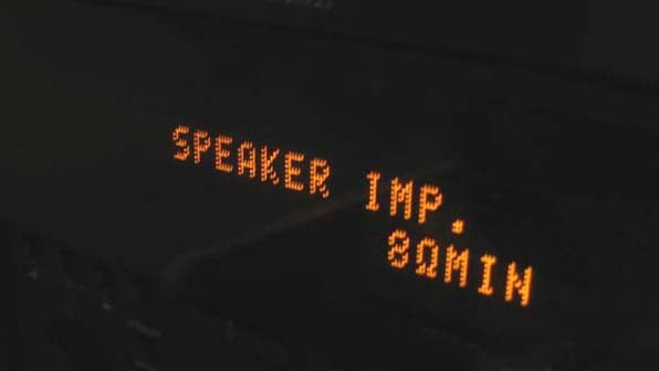
In long term testing of receivers such as the Yamaha RX-V2700 and RX-Z7, I've run both products in a 7.1 speaker configuration where at least 3 of the 7 speakers were 4-ohms rated and never ran into reliability or thermal issues at extreme continuous listening levels utilizing the high impedance setting. My center channel is 4-ohms rated, but I do apply the receiver's bass management at 80Hz to limit the bass output for that channel and redirect it to the dedicated subwoofer/LFE channel.
Use External Amplification
If you like to listen to music at loud levels and are using a speaker with a
tough load to drive and find that your A/V receiver is overheating and shutting
down, then you probably should purchase external amplification to compliment at
least the front channels. Today's modern A/V receiver is loaded with overload
and short circuit protection. Chances
are if you're over heating the receiver, it will shut down far before any real
damage can be done. That said, who wants
their musical experience to be shut down during a crescendo?
Amplifier power is cheap these days with very competently designed amplifiers
from the likes of Emotiva for as little as $299. External amplification for the front three
channels can really increase system dynamic range while the unused front
channels can be conveniently redirected for a second zone.
Use Bass Management
With most modern A/V systems, the users are advised to bass manage all of their
speakers sending power hungry bass signals to the dedicated powered subwoofer
channel. This takes considerable stress
of the power supply of your A/V receiver, allowing it to breathe more freely
while also providing more uniform bass
across all the listening seats.
Think more dynamic range, better bass, less heat. Any questions?.
Bottom Line
Budget A/V receivers represent a compromise of features vs. performance. They are typically optimized for 8-ohm loads because of limitations in the power supply and/or the output devices. Unless you are considering one of the mid to high end spectrum of their product offerings, chances are you're not getting an amp section that will adequately drive 4-ohm loads in either impedance setting.
 Don't think that flipping the impedance
switch in your receiver will be your miracle solution, because in this case it
certainly is NOT. What this really is in
most of the receivers I have tested is an inexpensive way to claim the receiver
is 4-ohm compatible
without the manufacturer having to actually spend money on better internal
parts in the power supply. In virtually all
of the receivers we've tested with impedance switches, flipping the switch to
the low setting would put your speakers at risk of receiving dangerously
clipped AC signals when attempting high output levels. While it may operate more safely for a
steady-state UL heat dissipation test, it's important to note the real world
tradeoffs once this switch is engaged in its low setting.
Don't think that flipping the impedance
switch in your receiver will be your miracle solution, because in this case it
certainly is NOT. What this really is in
most of the receivers I have tested is an inexpensive way to claim the receiver
is 4-ohm compatible
without the manufacturer having to actually spend money on better internal
parts in the power supply. In virtually all
of the receivers we've tested with impedance switches, flipping the switch to
the low setting would put your speakers at risk of receiving dangerously
clipped AC signals when attempting high output levels. While it may operate more safely for a
steady-state UL heat dissipation test, it's important to note the real world
tradeoffs once this switch is engaged in its low setting.
Know the facts when purchasing and setting up home theater equipment. An informed consumer makes smarter purchases. Most importantly, step back and evaluate how you are using your system and make adjustments accordingly and NEVER eat at restaurants that charge you full price for 1/2 the meal! Let the boss pay for those.
Gene manages this organization, establishes relations with manufacturers and keeps Audioholics a well oiled machine. His goal is to educate about home theater and develop more standards in the industry to eliminate consumer confusion clouded by industry snake oil.
View full profile