
Can Good Amplifier Design Mitigate Sonic Differences Between Cables?
Burning Amplifier: Too hot or not?
We uncovered an audio myth on our YouTube channel I didn’t even know was being perpetuated by some esoteric amplifier companies. Apparently there is a belief that designing an amplifier to be too stable and protected to prevent damage or fire during misuse or short circuiting will result in sound degradation.
Check out this conversation from the feedback on one of our YouTube videos on cables:
Regarding Cables and Amplifiers: Do high end expensive cables really make a difference?
Unwary consumer: Yes and no. There really ARE some very important differences... i.e. unshielded vs shielded cable etc and there's a lot of hogwash too. But I lost a very expensive amplifier once due to using the wrong choice of cable once and it sent it into oscillation (and then a fire!). so there.
Audioholics: then the expensive amp wasn't properly designed. A good amp doesn't oscillate b/c of a cable choice. It certainly should NEVER catch fire either.
Unwary consumer: not really
Audioholics: Yes really. As someone who designed and tested audio and RF amplifiers for 7+ years prior to running this website, I’ve never had an amplifier blow up or oscillate from a cable load. That is poor engineering and I wouldn't purchase another product from that company if it happened to me.
Unwary consumer: not at all. I think from the perspective of 'lowest common denominator' amplifier design that may be true... however higher performing amplifiers will make certain tradeoffs like eschewing protection circuitry in favor of greatly improved performance - in many of these cases (there are several manufacturers that do this) warranties are void unless you use a range of cables specified by the manufacturer.
Audioholics: Wow you’ve just uncovered a great myth for us to debunk that I didn't even know was being perpetuated by esoteric companies. Under NO circumstance does an amplifiers stability or safety need to be compromised for "improved' fidelity. That is total nonsense. Either the company is telling you that out of sheer incompetence, or they simply want to make the design as cheaply as possible while selling a lack of a feature as a positive. Which company is this? I'd love to explore their design a bit more in depth.
Audio and Speaker Cable Myths vs Truths Revealed
With that said, I reached out to a couple of very trusted amplifier designers from Classe and Emotiva to see what their thoughts were on this topic.
From Classe
Do speaker cables really matter? From the amplifier perspective the rational answer should be no, all correctly designed amplifiers need to be able to drive a given loudspeaker load with equal amplifier performance irrespective of speaker cable choice. Experience shows us that often this is not the case; some amplifiers will behave differently when speaker cables are interchanged. For the purpose of our discussion we will assume that the cable itself is not the variable; it is correctly engineered - having low DC resistance and reasonably low capacitance and inductance. Let’s have a look at two of the basic building blocks of a typical amplifier, depicted in Fig1. We notice the presence of an output network placed between the actual power stage and the speaker terminals. This multipurpose passive circuit accomplishes the following functions: it offers resistive loading (the series R1 and L1 circuit) at high frequencies for the power stage while also separating it from the adverse effects of capacitive loads. In other words this helps the power stage to maintain stability in a wide variety of speaker+cable combinations. Another function of the output network as presented in Fig1 is to prevent RF ingress from the outside world (the speaker cable may and also will act as an antenna radiating radio frequencies into small signal stages inside the power amplifier chassis). The parallel R2 and C1, and R3 and C2 elements are known as zobel networks whose purpose are to dump high frequency noise to ground.
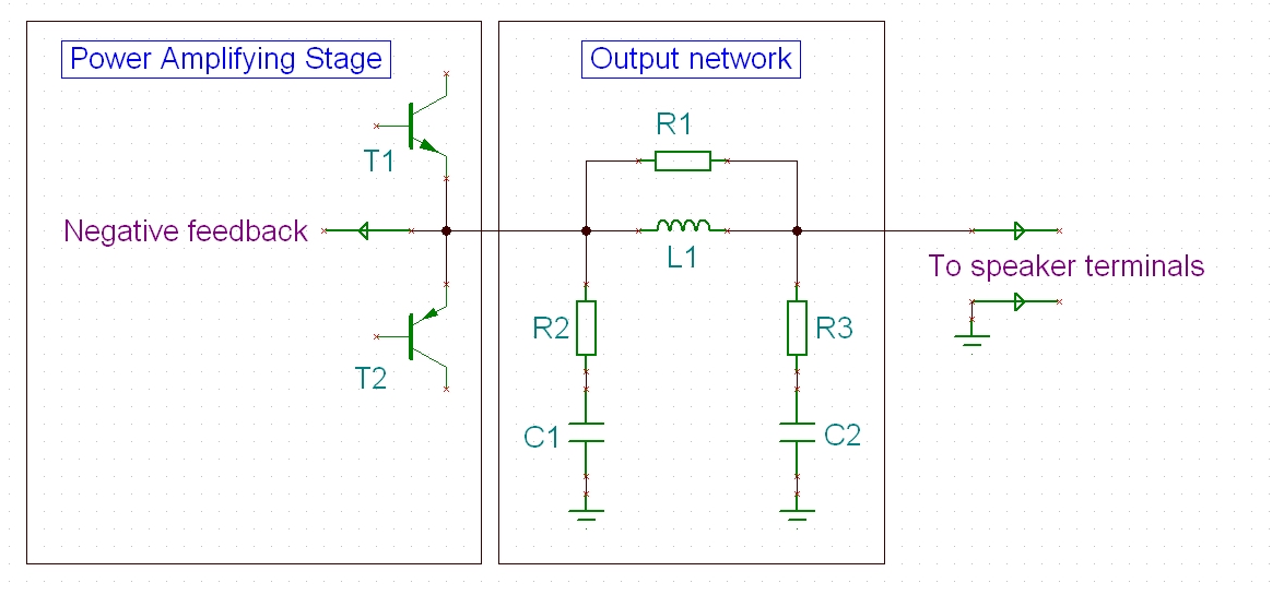
Fig 1. The typical power amplifier
Some designers may be concerned with the presence of elements R1, L1 placed in series with the output. These may indeed lead, when overdone, to an increasingly higher output impedance vs frequency adversely reducing the damping factor parameter specification - to the point where this may become audible. Therefore some may choose to use a simplified network as shown in Fig2. In itself not a bad thing as long as one is aware of the pitfalls of such an approach. Additional precautions may be necessary elsewhere in the circuit to preserve stability and RF immunity. Let’s peel another layer and analyze the case where the so called lead compensation is used to achieve the minimum stability margin (a capacitor such as C3 is placed across the feedback resistor R4). In the case of Fig2, while performing this functionality C3 will also inadvertently help bring in RF perturbations from outside the chassis directly to the input stage. Without going to details suffice to say that if the input stage uses bipolar transistors then various levels of RF will be detected which will adversely affect the biasing conditions and ultimately the distortion profile of the power amplifier. Such an amplifier will sound different dependent of how effective an antenna a particular speaker cable is. Of course in more extreme cases some amplifiers may also burst into oscillations which can lead to a fatal failure of the output stage.
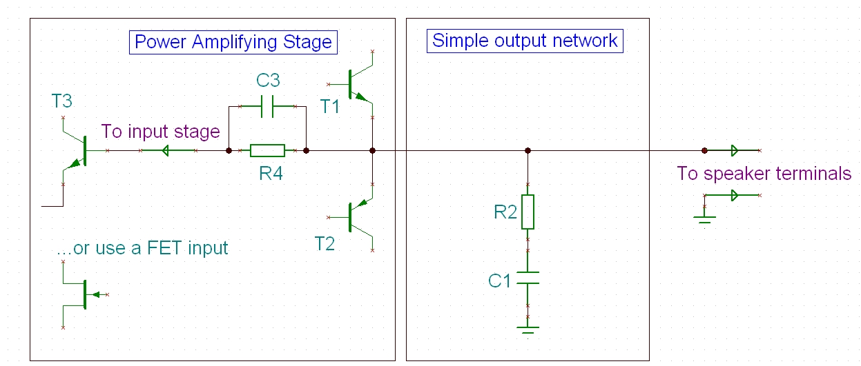
Fig 2. The “well intentioned” power amplifier
One well known cure for this particular “illness” is the adoption of a FET based input stage - used in conjunction with other circuit techniques this will avoid most of the EMI issues due to speaker cables.
This short example highlights only a particular case where things can go wrong.
The problem of interfacing a power amplifier with the outside world in the presence of a wealth of wireless devices, dimmers and SMPS powered office equipment placed in close proximity to our music systems has become an increasingly difficult challenge.
At Classé in particular we have traditionally used various combinations of design techniques that produced the same benefic results: amplifiers able to drive difficult loads with ease. (A short note: considering the long history of Classé and generations of designers, simply enumerating these solutions may lead to different/contradictory interpretations – what has always really mattered was the end result…J)
From Emotiva
A properly designed amplifier really shouldn’t care about the speaker cables and under normal circumstances, they don’t. However, there is always an exception to the rule and this is where adding a few extra parts to ensure stability under the widest range of applications as possible is well worth the time and additional cost.
Some designers use FETs for the differential circuits. We personally have always used bipolar transistors and do not have stability issues. The reason for this is probably because we prefer a different topology for the feedback circuit. Instead of putting a capacitor across the front side of the voltage divider that makes up the feedback loop, we always put it across the back side. By doing this it takes any induced high frequency of oscillations and sends them to the isolated ground. This offers a great deal of stability to the amp without affecting the overall sound quality of performance. In addition to the feedback loop, there are other places within the design that work to stabilize the amplifier like the C Dominant pole across the VAS stage, but that is a whole other discussion in itself.
The Bottom Line
Using passive devices to improve stability and reject RF from the outside world is arguably more beneficial to the sound than trying to forgo these techniques under the misguided notion that there won’t be any negative consequences from oscillations or RF being allowed inside the amplifier. Design involves trade-offs and in this case, having no output network at all gives both risk and sonic compromise.
The takeaway conclusion especially applied to today’s systems is that a specialist power amplifier company & design team must always be aware of the challenge: make informed design decisions with the ultimate goal of producing high performance equipment compatible with a wide range of cables and speakers.
Gene manages this organization, establishes relations with manufacturers and keeps Audioholics a well oiled machine. His goal is to educate about home theater and develop more standards in the industry to eliminate consumer confusion clouded by industry snake oil.
View full profile