
Velodyne SMS-1 Subwoofer Parametric EQ System Review
Velodyne SMS-1 Subwoofer Parametric EQ System
- Product Name: SMS-1 Subwoofer Parametric EQ System
- Manufacturer: Velodyne Acoustics
- Performance Rating:


- Value Rating:
- Review Date: April 09, 2006 19:00
- MSRP: $ 749
|
|
Pros
- Automatic or manual subwoofer calibration
- On-screen display
- 8-band fully parametric EQ
- Includes microphone and various mounts
- Multiple SMS-1 units can be daisy-chained
- Works with any subwoofer
Cons
- 3rd octave smoothed frequency response graph
- Non independent EQ'd subwoofer outputs
- Inaccurate (aggressive) auto calibration
Velodyne SMS-1 Subwoofer Parametric EQ System Introduction
We were introduced to the Velodyne SMS-1 system at the CEDIA show in Indianapolis last year and were instantly impressed with its potential for improving how subwoofers interact with the room. The SMS-1 is basically Velodyne’s flagship Digital Drive room correction software offloaded into a standalone system that allows it to be used with any (even *gasp* non-Velodyne) subwoofers. The SMS-1 is essentially an 8-band parametric EQ with variable frequency, Q, and gain that shows you a real-time smoothed graph of the room’s low frequency response from 15Hz to 200Hz via an on-screen display.
What does this mean for you? Well, in a practical sense, those of you desiring the most out of your subwoofer and room can make changes to your system in real-time and see the results on-screen. Additionally, once you’ve found the optimal positioning and phase settings, you can provide the final touches to your bass response using the integrated EQ system – taming room modes and eliminating some of the peaks and dips that are inherent to almost every system.
Velodyne SMS-1 Parametric EQ System Overview
Using the System: The Basics
Setting up the SMS-1 is a simple process. Though the user manual reads more like a dictionary than a procedural instruction set, the SMS-1 is really quite easy to use. Here is a “birds eye” view of the entire calibration process:
- Connect the bass-managed “subwoofer” output from the receiver to the LFE input of the SMS-1 (do not disable bass management on your receiver as suggested in the SMS-1 manual)
- Connect the stereo RCA outputs and composite video out from the SMS-1 to an available input on your receiver
- Power up the SMS-1
- Position the included microphone at the main seating position and connect it to the front XLR input of the SMS-1
- Select a ‘Preset’ on the remote control (we suggest starting with #5). At the main menu of the SMS-1 system hit the ‘Menu’ button and press ‘12345’
- Ensure that the ‘LOW PASS XOVER FREQ’ is disabled
- Make manual subwoofer and room adjustments first to get the best possible room response (move the sub, close doors, move furniture and seating/mic position, select the proper bass management and crossover settings on your receiver, etc)
- Use the 8-band parametric EQ to make final tweaks to the room’s frequency response at the main listening position
- Test the other seating areas and make sure you do not drastically reduce quality in the secondary seats while optimizing the primary listening position
Velodyne SMS-1 Features and Using the System
Using the System: Breakdown of Features
Though the setup process for using the Velodyne Subwoofer Management System is direct and uncomplicated, there are several options that should be understood so that you get the most out of the system. You can also negatively affect the bass management in your system if you are not careful to set the low pass crossover frequency correctly (or defeat is as we’ll point out).
Inputs and Connections
While the front of the SMS-1 only sports a power button, LCD panel and XLR microphone input, the rear of the unit is loaded for bear. A balanced LFE Input and Output (yes, just one) plus additional Mic Input garner the rear of the unit in addition to an RS-232 Input and Output and IR Input. S-video and composite video connections are provided to get an on-screen display which is necessary for making adjustments on the SMS-1. There are three unbalanced “LFE” outputs (for attaching up to 3 subwoofers in parallel). An EQ output provides the necessary sweep tone and calibration outputs which get routed to your AV processor/receiver.
Though we would have liked to have seen the ability to independently EQ two subwoofers in the SMS-1, we recognize it would complicate setup for most end users of single subwoofer systems. In some cases, EQ’ing just one sub in a multi subwoofer system will do the trick nicely. For instances where additional EQ’ing is needed, the SMS-1 has the ability to be daisy changed to additional units to make it a reality. A “Thru” connection (stereo) routes pure, un-EQ’d signal out of the SMS-1, allowing for daisy-chaining of multiple units. The unbalanced “Output” RCA connections provide an 80Hz 6dB/octave high pass crossover for use with systems that do not provide adequate bass management. Lastly, as far as unbalanced RCA connections go, there are a pair of LFE inputs, with a mono Right channel input for those in the majority who have mono subwoofer outputs from their receiver or processor. Speaker level inputs (bare wire terminals) and a 12VDC trigger are also provided.
![]()
Connections a-plenty reside on the rear of the SMS-1
Understanding the Real-Time Frequency Response Graph
Upon entering the Setup system a low frequency (15Hz – 200Hz) sweep tone will begin. This will allow you to see how the low frequency room response is measured at the microphone position. As best we can tell, in accordance with comparative LMS measurements, this is a 1/3-octave smoothed response giving users a general idea of both the overall bass response of the system along with a look at how well the subwoofer integrates with the main speakers at the crossover point.
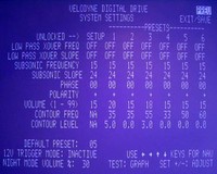 The System Settings

The system settings menu is where you should start in order to ensure you are properly configured prior to making manual EQ adjustments. This is the place where you can really tweak the system and fine tune what the SMS system will do for each preset mode.
LOW PASS XOVER FREQ/ LOW PASS XOVER SLOPE
This
function sets the frequency above which the SMS-1 will apply the LOW PASS XOVER
SLOPE (set as any range from 15Hz – 199Hz in 1Hz steps). The LOW PASS XOVER
SLOPE is configurable from 6 – 48dB/octave in 6dB/octave step sizes. We
recommend DEFEATING this function by placing the cursor over the LOW PASS XOVER
FREQ and hitting the “Reset” button on the remote control. This will cause the
XOVER FREQ and SLOPE to register “OFF” as their value across all presets. As the
majority of users will have adequate bass management present on their receivers,
there is no reason to either double up or defeat the bass management functions
of the AV processing device. In fact, it is highly likely that by disabling bass
management on the receiver (as recommended by Velodyne’s SMS-1 User Manual) you
could cause problems such as missing frequency response from surround and center
channels, overdriving surround channels to distortion, and wasting amplifier
power by driving full range audio to loudspeakers that do not support it.
SUBSONIC FREQUENCY/SUBSONIC SLOPE
This setting is
typically not needed for most systems, but enables the user to cap the lower
frequency limit that the SMS-1 will allow. This could, for example, save a
delicate (ie. underperforming) subwoofer from getting too much low frequency
information that would otherwise distort and possibly damage the driver or
amplifier. It can be configured from 15Hz – 35Hz in 1Hz increments. The 15Hz
default will be sufficient for most systems attempting to get the lowest
possible frequency response. The SUBSONIC SLOPE can also be set to either 6, 12,
18, 24, or 48db/octave.
PHASE
This self explanatory setting allows you to
adjust the phase of the SMS-1’s output signal from 0 to 180 degrees in 15 degree
increments. Phase can be utilized to effectively “delay” the subwoofer signal
and better time align it to the system or create a flatter overall room
response.
POLARITY
You can switch the polarity of the
subwoofer output to + or – which flips the subwoofer out of phase by 180
degrees.
VOLUME
The Velodyne Subwoofer Management System
allows each Preset to have its own volume setting. This is good, for example, in
the event that you simply want your subwoofer set higher for action/adventure
movies (Preset 1) or Pop/Rock (Preset 3).
CONTOUR FREQUENCY/CONTOUR LEVEL
The point of this
setting is to allow a “bump” or “cut” in the frequency response in order to
accentuate a small frequency area for particular presets. You could use this to
give an extra boost around 60Hz during Action/Adventure movies for example – or
to pump up the 40Hz response for your favorite Hip Hop tunes (no, there isn’t a
‘Hip Hop’ preset, but you get the idea).
The final controls on the System Settings screen are 12V TRIGGER MODE and NIGHT MODE VOLUME. The first setting shuts off the SMS-1 until a 12V DC current is fed to the 12V trigger input on the rear of the unit. The latter, is intended to provide a night listening mode which could cap the subwoofer volume so as to keep late night movies from waking the other household members. We initially thought NIGHT MODE was inoperable since engaging it at even its lowest setting didn’t appear to make an audible difference when listening to music. It wasn’t until we popped in the DVD Toy Story 2 and listened to the opening scene where Buzz Lightyear was blasting his rockets into space that we heard our subwoofer cap off its output during the loud passages. Measuring with an RMS meter to confirm we watched the steady state signal of 200mVrms from Buzz’s rockets fizzle out to around 20-40mVrms with NIGHT MODE engaged at 10%. This feature acts more like a limiter than an active gain control or compressor, which was what we thought its function was supposed to be prior to testing it.
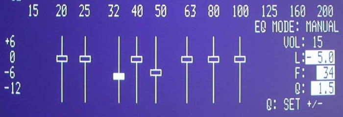
Using the 8-band Parametric EQ
Below the real-time system response graph are 8 sliders which can provide +6 dB gain or -12dB cut. Once you have optimized subwoofer placement and done as much as possible to optimize the physical room and listening position, you can raise and lower the sliders to help smooth out the in-room low frequency response. We recommend mostly cutting frequencies, though if you can achieve a better in-room response by adding a dB or two of gain in some areas (without negatively affecting the secondary listening positions) then feel free to try that as well. Rarely will dramatic EQ boosts improve overall sound as you cannot dramatically increase what is not there to begin with.
The “Test” button on the remote control sends the user back and forth between the System Settings menu and the System Response screens.
When using the EQ you can jump from band to band by arrowing left and right. Pressing the up/down navigation/arrow keys while on an EQ band allows you to raise and lower the gain at that frequency. Clicking the ‘Select’ button will allow you to “move” the frequency and you can select the ‘Set’ keys to raise and lower the Q value.
Velodyne SMS-1 EQ Adjustment Evaluations
EQ
Adjustment Evaluations: Manual EQ
In Reference System 2 we noticed some very
enlightening and amusing room anomalies. While running the SMS-1 system in
SYSTEM RESPONSE mode and allowing the system to provide real-time updates to the
frequency response graph, I went around the room and opened and closed doors to
see what would happen to the low frequency room response at the listening
position. This is the standard configuration of my room with some minor
optimization with the SMS-1 system.
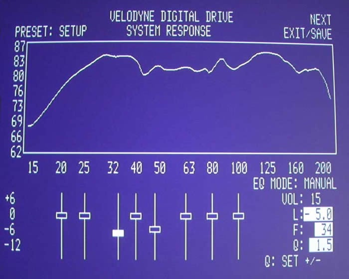
Optimized Reference System 2 (we only took out -5dB
at 34Hz and -4dB at 48Hz)
But notice what happens when we open a closet door in the rear of the room, effectively adding 4’ of depth to the room and changing the overall makeup of the system:
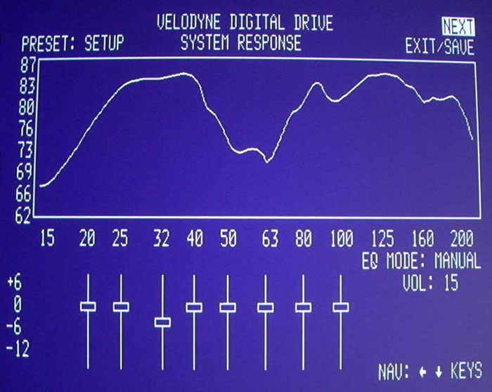
Room response at primary listening position with
rear closet door opened.
Yowza! That’s roughly a 10dB suckout between 40 and 80Hz! It is important to pay attention to closets and anything that will affect the size of the room and how the subwoofer pressurizes the listening environment.
To give you an idea of the potential room modes you may have to deal with, we recommend using the following calculation to plot your trouble spots and map out any potential frequencies you will have to deal with:
F = m1130/2D
Where:
F = frequency of the resonance mode in Hz
m = mode harmonic (first = 1, second = 2, third = 3, etc)
D = distance between two parallel surfaces in feet
1130 = approximate speed of sound in feet/second
Here are the room mode points for Reference System 2:
|
Room Mode |
16.0 (L) |
13.3 (W) |
9.0 (H) |
|
First |
35.3Hz |
42.5Hz |
62.8Hz |
|
Second |
70.6Hz |
85Hz |
125.6Hz |
|
Third |
106.9Hz |
127.4Hz |
188.3Hz |
|
Fourth |
141.3Hz |
169.9Hz |
251.1Hz |
The areas marked in red are the room modes that can be potentially troublesome since they compound between first, second, and third harmonics – making the net effect worse than if none of the frequencies overlapped.
EQ Adjustment Evaluations: Auto EQ
We knew what the best setting for the room was after
evaluating the system manually and making our adjustments. Now it was time to
see how the SMS-1 would treat the room when running in Auto EQ mode. We weren’t
surprised when, like a doctor fresh out of medical school, the SMS-1 was a bit
overeager in wanting to solve all of our low frequency problems. To give it a
really difficult (but still real-world) task, I opened up the closet door at the
back of the room and let the Auto EQ mode “have at it”.
We see here a nice deep cutout between 45 and 65 Hz. Typically in a room like this you would want to play with phase a bit before attempting to EQ-out a gaping hole of this size (which is honestly, impossible to fix via EQ).
Here is the SMS-1’s interpretation of the solution:
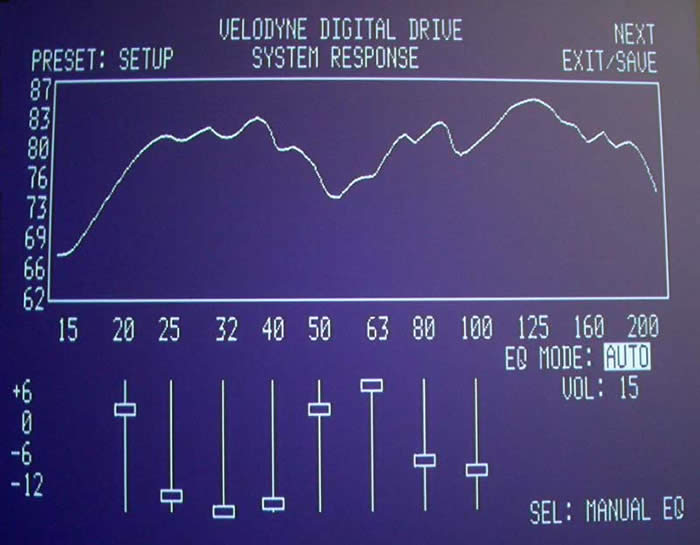
Does the graphed frequency response look better? Well, yes – but to understand more about what is happening we need to examine the settings. The Velodyne applied over 9dB of gain (in two bands) from 50-60Hz. This boosted frequency information that really wasn’t there to begin with – at least not in the way you think. In an attempt to smooth over the large hump from 25-40Hz, the Velodyne applies an equally aggressive cut in gain – this time over 30dB combined across the affected frequencies. The Velodyne SMS-1 system is simply applying its parametric EQ in an intelligent way to get the results to match a flatter curve. And, at that, it is doing an excellent job. What the user will need to understand is that it is IMPERATIVE to get the subwoofer integration as good as possible before allowing the SMS-1 to take over and adjust the levels to smooth out the response. Close those doors, move the sub, adjust phase – do what ever it takes to get a better starting point. Then, allow the SMS-1 to work its magic, or better yet do a manual adjustment and dial in the frequency response to a more realistic setting to avoid needless over boosting or cutting of frequencies.
Velodyne SMS-1 Measurements and Analysis
Test Case #2 – Compensating for Room Conditions
The following measurements and analysis was conducted in Family Room System #1 of the Audioholics Showcase Home. This is a most challenging room since it is open-ended, making it all but impossible to pressurize the room no matter how many high caliber subwoofers you integrate. Since the room is essentially a larger home theater room in terms of cubic feet, predominant low frequency bass modes aren’t quite as prevalent as one would see in typical rectangular shaped rooms with the listener within a few feet from a back wall. Suffice it to say, the listening position still incurs uneven bass response. Only passive room correction (ie. bass traps) and a PEQ system such as the Velodyne SMS-1 can improve upon, short of relocating the subwoofer or listening position which are two variables not able to be manipulated any more optimally than they currently are without severely sacrificing room functionality or aesthetics.
Measurements & Analysis
The subwoofer of choice used for these tests was no other than the Axiom EP500. The subwoofer response was set to flat via the back panel EQ’ing options. Its optimal location was found using our Crawling for Bass techniques in conjunction with the Sencore SP-295C FFT Audio Analyzer.
We settled upon a front left wall placement about six feet from the corner and directly behind the left couch. While the sub performed quite well on its own, it was obvious that further tweaking beyond level, crossover frequency and time delay was needed in order to linearize its in-room response and achieve a better splice between the bass-managed speakers. In this case all of the speakers in the system were bass-managed.
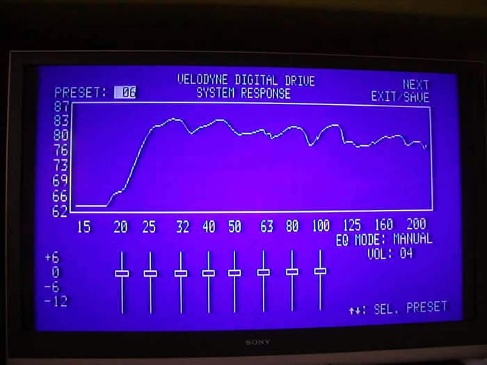
Figure 1. Screenshot of SMS-1 in bypass mode
The response here looks too good to be true showing 80dB +3/-4dB response from 20Hz to 200Hz. The response shown appears to be smoothed, perhaps 1/3 octave or so.
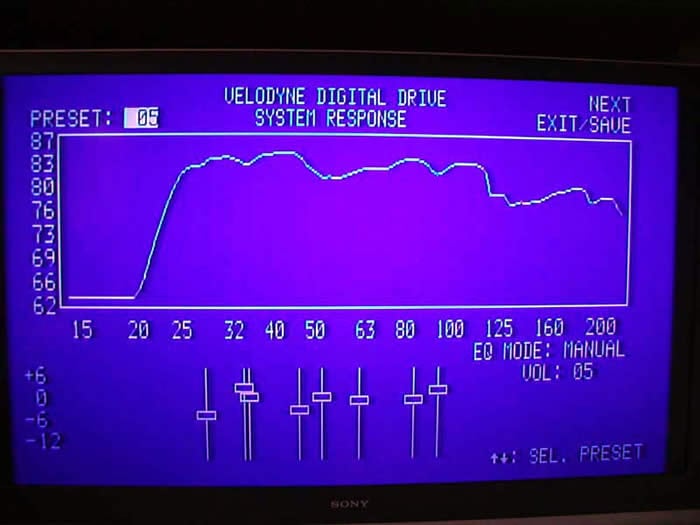
Figure 2. Screenshot of SMS-1 after Custom Calibration
With some fine tuning of frequency, Q and level at selective bands, I managed to smooth out the low end frequency response and reduce some of the bumps and dips in the response, particularly below 25Hz and at the crossover region (80-100Hz).
I wanted to see a more accurate representation of the system response, so I hooked up my LMS system to measure pre and post calibration.
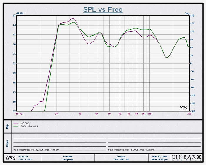
Figure 3. Listening Position Measurement of SMS-1, 1/3 octave smoothed
Purple Trace: SMS1 Bypassed, On Axis Listening Position Measured response was +/- 5dB from 20Hz to 100Hz
Green Trace: SMS1 On Axis Listening Position response was 81dB +/- 4dB from 20Hz to 100Hz
The suckout from 30-40Hz was significantly reduced 3dB which required a boost of a couple of key frequency of the SMS-1 between 1 to 2 dB. A peak at 25Hz was reduced by 2dB while the response was flattened down 2dB from 80 to 100Hz, thus improving the splice between the subwoofer and bass managed speakers. The dips centered around 120Hz is a measurement anomaly caused by the mic position relative to the floor and satellite speakers woofers (more on this later). This dip is not a true response at the listening position and should be ignored. The 50Hz dip is a bit more complicated and will be discussed later on in this review addendum.
A note about boosting: use the boost option sparingly to avoid excessively overdriving your subwoofer or its amplifier. It’s usually not a good idea to boost, but if you see a null improve by adding 1-2dB of gain, then it might be a good idea to take advantage of it. As always, when making these adjustments take care to spot check adjacent areas to ensure that you are not creating large dips and peaks for seats outside the primary listening position.
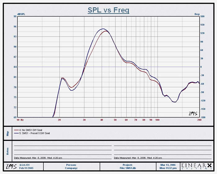
Figure 5. Left Listening Position Measurement of SMS-1 System Response, 1/3 octave smoothed
Red Trace: SMS-1 Bypassed, Off Axis measurement
Blue Trace: SMS-1 Off Axis measurement
I picked the worst possible seat in the room which was about 2 feet from the subwoofer near the left side wall which incidentally has the worst viewing angle. This is the seat you stick your mother in law in, or your pesky neighbor who always unexpectedly shows up to watch a sporting event or movie on your system. You can see about a +12dB bump centered around 40Hz from a resultant room mode indicating this is not a good seat unless you are into gangster rap music, or want to feel the nauseating tactile response of the EP500 at full tilt during explosion scenes from War of the Worlds. Trust me I sat though this when entertaining some “invited “guests and it felt as if my couch was loaded with tactile transducers.
The point of this measurement was to show that even in the worst listening location, the SMS-1 didn’t muck up the response despite the fact I EQ’ed the sub in the optimal listening area. By doing so, it helped take away some of the energy in the room that would otherwise excite dominant modes, which is evident by the improvement in system bass response of -3dB from 40Hz down to 30Hz.
Although the system’s bass response sounded cleaner and had more punch to it, I wasn’t completely satisfied and decided the next day to spend more time tweaking it via more refining PEQ band manipulation, LMS, and a lot of patience. If you aren’t yet a believer of the Axiom EP500’s capabilities, then I suggest you get my neighbor’s dogs’ opinion. In the process of calibrating, about four of my neighbor’s dogs were going nuts, creating quite a ruckus. I could hear my neighbors yelling at their animals - not understanding why they were barking so much for no apparent reason. I didn’t have the heart to tell them why.
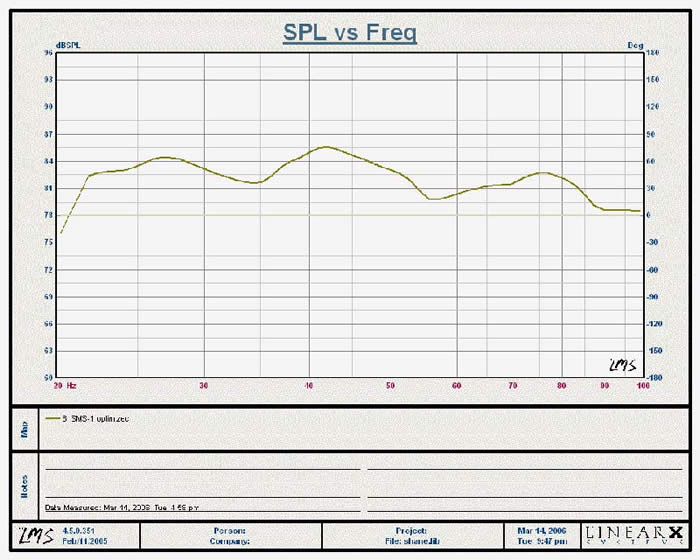
Figure 6. Optimized Subwoofer Response with SMS-1 Engaged, 1/3 octave smoothed
The response was a bit smoother than what I was able to accomplish the prior day. I did sacrifice a little low end response below 22Hz but moving my couch a few inches along with tweaking the PEQ helped to reduce a significant null in the 70-90Hz range which is much more perceivable than losing a few dB below 22Hz. The overall response from 22Hz to 100Hz +2/-3dB. Very good indeed!
Velodyne SMS-1 Measurement Notes and Conclusion
When measuring a loudspeaker in a room, it’s important to interpret the results accurately. More often the case than not, a pesky dip in a certain area is either a result of a reflection caused by the wavelength distance relationship between the microphone and floor or the relationship between the distance of the speaker’s woofers and nearby boundaries, such as the wall behind it.
Some guidelines in
interpreting what is real and what isn’t include:
- Does the measurement anomaly go away when you move the microphone?
- Does the measurement anomaly coincide with impedance curve of the system?
- Does the measurement anomaly coincide with 1/2 wavelength of mic position relative to the ground?
- Does the measurement anomaly persist even after you try boosting that frequency range?
If you answered YES to #1and #3 and #4 and NO to #2, you are likely dealing with a measurement anomaly. If you answered YES to #1 and #4, and NO to #2 & 3 it is likely you are dealing with a room node.
If you have seen evidence of impedance curve anomalies at 50 or 120 Hz, you may be looking at some sort of system-sourced pathology. It is assumed, of course, the system wasn’t designed with major dips at 50 & 120 Hz!
It’s not unusual to see odd or unexpected glitches show up in the impedance curves of loudspeaker systems. That they do is no surprise, as what occurs in the acoustical or mechanical system is also reflected in the electrical system, producing small impedance peaks & dips. On those occasions when these oddities occur, identifying their magnitude, frequency and\or Q can provide information useful in tracking down the cause, whether it be systemic or arising from the interaction of the system with its environment.
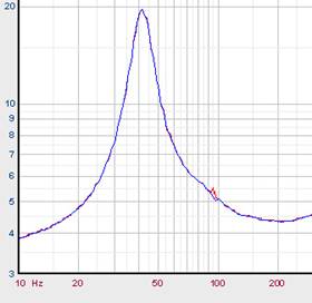 In the figure here, we
see a classic example of an acoustic event (one of my youngsters thumping around
directly above the area where I happened to be doing an impedance sweep on a
totally enclosed box system). The blue curve is the sweep done when all was
quiet. The red curve was done when youngest daughter was doing cartwheels on the
floor above, producing a momentarily noisy measurement environment.
In the figure here, we
see a classic example of an acoustic event (one of my youngsters thumping around
directly above the area where I happened to be doing an impedance sweep on a
totally enclosed box system). The blue curve is the sweep done when all was
quiet. The red curve was done when youngest daughter was doing cartwheels on the
floor above, producing a momentarily noisy measurement environment.
If you have a case where you suspect your cabinet is causing anomalies in either your dB SPL curves or impedance curves, think in terms of wavelength, λ.
Focusing now on dB spl response curves, unintended acoustic response curve anomalies often occur as a result of reflections, standing waves, or other such mechanical or acoustical resonance phenomena which directly relate to things such as panel dimensions, edges, and distance to nearest room boundaries.
First, find the wavelength of your observed dips (in this case 50Hz and 120Hz), by simply dividing the velocity of sound (c ≈ 1130 ft/s) by the frequency. 1130 ft/ s divided by 120Hz gives 9.4 Feet or about 113 Inches. A half-wavelength would be about 57 inches. At 50 Hz, the half-wavelength would be about 136 inches. Neither of those figures relates to any cabinet dimensions in a meaningful way and nothing appears to be out of sorts or otherwise unusual with the system impedance curve, so the cabinet isn’t the culprit.
Measurement Notes by Gene DellaSala
- 57 inches is about the distance between the mic and floor.
- 136 inches is about the distance between the speakers and the couch where the measurement was being conducted and is also about the distance between the subwoofer and an opening to a hallway where the two guest rooms and bathroom reside.
Conclusion
The Velodyne SMS-1 is a fantastic tool for dialing in subwoofers and adding those final touches to tweaking your system for optimal performance. It also offers an incredible “real-time” look at exactly how your room interacts with the subwoofer. All in all, the SMS-1 response graph was quite a useful tool in helping to fine tune system response. For those without the benefit of an Audio Analyzer or LMS measurement system, you should be able to achieve satisfactory results using the Velodyne OSD measurement display. This system works and, depending on your room conditions and subwoofer system, it can be that little helping hand to tweak out your system response. In some systems it could even make a world of difference to combat room issues while opening up more placement options for your subwoofer(s) previously unattainable without a minimum phase adjustable PEQ system.
With the SMS-1 you may never have to Crawl for Bass again. One thing to remember is that this is a tool. And like all tools it must be used properly. Consumers who think they can toss their subwoofer anywhere and use the SMS-1 to sort out the pieces will be disappointed with the results. Those who understand that the SMS-1 will allow them to make adjustments to subwoofer placement, room treatments and then dial in the subwoofer for those final touches are sure to be very pleased indeed.
If you haven’t dealt with subwoofer to room integration part of your system yet, you will be amazed at how much more articulate and natural sounding your subwoofer(s) will sound when properly equalized. As always, do the best job you can passively treating your room for the most balanced and consistent sound possible. Then, throw in an SMS-1 or two to fine tune your systems bass response and further push the envelope of performance.
We give a hearty recommendation to this tool and think that everyone who is serious about bass could stand to gain from integrating an SMS-1 into their listening room.
The Score Card
The scoring below is based on each piece of equipment doing the duty it is designed for. The numbers are weighed heavily with respect to the individual cost of each unit, thus giving a rating roughly equal to:
Performance × Price Factor/Value = Rating
Audioholics.com note: The ratings indicated below are based on subjective listening and objective testing of the product in question. The rating scale is based on performance/value ratio. If you notice better performing products in future reviews that have lower numbers in certain areas, be aware that the value factor is most likely the culprit. Other Audioholics reviewers may rate products solely based on performance, and each reviewer has his/her own system for ratings.
Audioholics Rating Scale
 — Excellent
- — Very Good
- — Good
- — Fair
- — Poor
| Metric | Rating |
|---|---|
| Audio Performance | |
| Build Quality | |
| Ergonomics & Usability | |
| Ease of Setup/Programming/Integration | |
| Features | |
| Remote Control | |
| Performance | |
| Value |
Clint Deboer was terminated from Audioholics for misconduct on April 4th, 2014. He no longer represents Audioholics in any fashion.
View full profile